LIFTING THE EXCAVATOR
Figure OI-138
Procedure 1 Figure OI-137 2 1
2
1 P-49277A
Fully extend the cylinders of the bucket, arm, and boom so that the excavator is in the position as shown [Figure OI-137]. Raise the blade all the way.
Install a one inch (25 mm) bolt and nut (Grade 5 or 8) through the holes at the boom (Item 2) [Figure OI-137] and [Figure OI-138]. Fasten a chain from the bolt to the lift device.
Position upperstructure so the blade is to the rear.
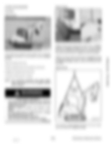
Figure OI-139
Engage the upperstructure slew lock. Put all the control levers in neutral. NOTE: For machines equipped with angle blade, make sure blade is in the straight position prior to lifting.
WARNING •
• • • •
AVOID INJURY OR DEATH Use chains and lifting equipment with sufficient capacity for the weight of the excavator plus any added attachments. Maintain center of gravity and balance when lifting. Do not swing boom or upperstructure. Engage the upperstructure slew lock. Never lift with operator on machine. Never lift with the blade angled (if equipped).
MS-4778A
W-2580-0607
The maximum angle between the front and rear chains must not exceed 45° [Figure OI-139].
OI-64 88 of 177
335 Operation & Maintenance Manual
Dealer Copy -- Not for Resale
Fasten chains to the ends of the blade (Item 1) [Figure OI-137] and [Figure OI-138] and up to a lifting device above the canopy/cab. Place protective material between the chains and the ROPS / tailgate to prevent damage.
P-49275B


