2 minute read
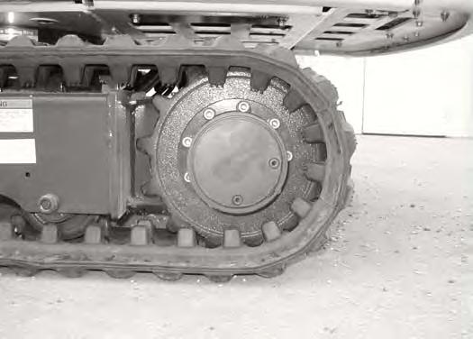
TRAVEL MOTOR


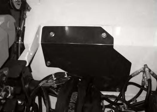
Checking And Adding Oil
Figure PM-51
Put the machine on a level surface with the plugs positioned as shown (Items 1 & 2) [Figure PM-51]
Remove the plug (Item 1) [Figure PM-51]. The oil level should be at the bottom edge of the plug hole.
Add SAE-90W gear lube through the hole if the oil level is below the hole (each motor).
Install and tighten both plugs.
Repeat the procedure for the other side.
Removing And Replacing Oil
(See SERVICE SCHEDULE on Page PM-5) for the correct service interval.
Put the machine on a level surface with the plugs positioned as shown (Items 1 & 2) [Figure PM-51]
Remove the bottom plug (Item 2) and top plug (Item 1) [Figure PM-51] and drain into a container. Recycle or dispose of the used lubricant in an environmentally safe manner.
After all the gear lube is removed, install plug (Item 2) [Figure PM-51]
Add 0.53 qt. (0,5 L) of SAE-90W gear lube to the plug hole (Item 1) [Figure PM-51] until the gear lube level is at the bottom edge of the plug hole (each motor).
Install and tighten the plug.
Repeat the procedure for the other side.
Alternator Belt

Belt Adjustment
Replace the belt if it has stretched or there are cracks in the belt. Replace the pulley if the belt contacts the bottom of the groove in the pulley.
Stop the engine.
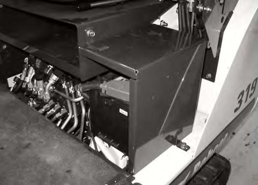
Remove the 2 blade extensions (Item 1) [Figure PM-52] from the storage compartment.
Use the start key to remove the access cover (Item 2) [Figure PM-52]
Remove the 2 bolts (Item 1) [Figure PM-54] and nuts from both sides of the seat mount.

Remove the bolt (Item 2) [Figure PM-54], nut and bracket from the right side of the seat mount.
Loosen the 2 bolts (Item 3) [Figure PM-54] and nuts from both sides of the seat mount.
Remove the seat and seat mount.
Remove the 2 bolts (Item 1) [Figure PM-53] and brackets from the battery cover.
Remove the cover (Item 2) [Figure PM-53]
Remove the 4 bolts (Item 1) and remove the access panel (Item 2) [Figure PM-55]
ALTERNATOR BELT (CONT’D)
Belt Adjustment (Cont’d)
Figure PM-56
Loosen the alternator mounting and adjustment bolts (Item 1) [Figure PM-56]
If a belt tension tool is available, move the alternator toward the front of the machine [Figure PM-56] until the belt has (New belt = 56 - 60 lbf. or Used belt = 48 - 52 lbf.) tension.
If a belt tension tool is not available, move the alternator toward the front of the machine [Figure PM-56] until the belt has 0.50 inch (13 mm) movement at the middle of the belt span with 13 lb. (58 N) of force.
Tighten the mounting and adjustment bolts.
Install the access panel, the seat and seat mount, the battery cover, the access cover and the 2 blade extensions.
Belt Replacement
(See ALTERNATOR BELT on Page PM-32) for removal of components to access the alternator belt.

Loosen the alternator mounting and adjustment bolts (Item 1) [Figure PM-56] and loosen the belt all the way.
Remove the belt and install a new belt.
Adjust the belt as shown above.
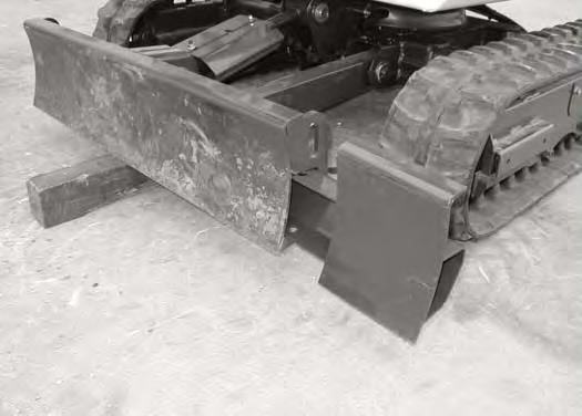
BLADE EXTENSION Description
The blade extension are used to match the track width to the blade width. Remove the blade extensions when transporting the excavator or when a narrow operating width is needed. Under normal operating conditions, the blade width should match the track width.
Installing And Removing
Figure PM-58
The blade extensions (Item 1 and 2) [Figure PM-57] are stored under the operator seat.
NOTE: The blade extensions needed to be installed under the operator seat as shown for cab models. Both mounting pins must be installed in the left blade extension (Item 1) [Figure PM57]. If the blade extensions are installed differently, breakage to the water bottle and cap could result.

Put a block (Item 1) [Figure PM-58] under the blade.
Fully lower the blade to the block.
Stop the engine.
Slide the extension (Item 2) [Figure PM-58] into the blade frame (both sides).

Install the pin (Item 1) [Figure PM-59] and spring clip (both sides).
Remove the blade extensions when transporting the excavator or when a narrow operating width is needed. Under normal operating conditions, the blade width should match the track width.