8 minute read
ELECTRICAL SYSTEM


Description
Figure PM-26
The excavator has a 12 volt, negative ground electrical system. The electrical system is controlled by fuses and relays located in the right side of the engine compartment (Items 1 & 2) [Figure PM-26]. The fuses will protect the electrical system when there is an electrical overload. The reason for the overload must be found before starting the engine again.
Fuse And Relay Location / Identification

Figure PM-27
1. Instrument - 10A (SW) Hourmeter, Warning Buzzer & Fuel Gauge Back Light
2. Accessory - 20A (SW) Accessory Connector, Heater & Horn
3. Start - 20A (SW) Key Switch, Unswitched Accessory Connector
4. Cab - 15A (SW) Cab Power, Lights, Wiper & Dome Light
5. Power - 15A (UNSW) Appliance Socket
6. Timer Power - 15A (UNSW) Stop Timer Module
7. Power - 15A (SW) Stop Timer Module
8. Open - Not Used [Figure PM-27]
Always replace fuses using the same type and capacity.
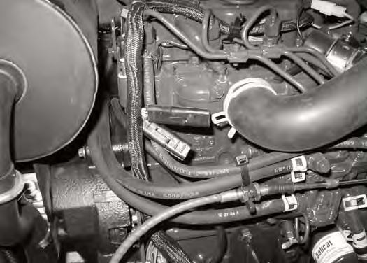
The three electrical relays (Item 2) [Figure PM-26] are located in the engine compartment to the right of the fuel fill. The three relays control the starter, glow plugs and switched power circuits.
ELECTRICAL SYSTEM (CONT’D)

Fuel Timer And Diode Location / Identification

ELECTRICAL SYSTEM (CONT’D)
Battery Maintenance
Figure PM-31

The battery is located under the cover (Item 1) next to the operator's seat. Remove the 2 bolts (Item 2) [Figure PM31] and brackets to open the cover.
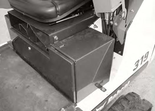
Figure PM-32
The battery cables must be clean and tight [Figure PM32]. Remove acid or corrosion from the battery and cables using a sodium bicarbonate and water solution. Cover the battery terminals and cable ends with battery saver grease to prevent corrosion.

Check for broken or loose connections.
If the battery cables are removed for any reason, disconnect the negative (-) cable first. When installing the battery cables, make the last connection the negative (-) cable to the battery.
The original equipment battery is maintenance free. If a replacement battery is installed, check the electrolyte level in the battery.
If the electrolyte level is lower than 0.50 inch (13 mm) above the plates, add distilled water only.
Warning
Batteries contain acid which burns eyes and skin on contact. Wear goggles, protective clothing and rubber gloves to keep acid off body.
In case of acid contact, wash immediately with water. In case of eye contact get prompt medical attention and wash eye with clean, cool water for at least 15 minutes.
If electrolyte is taken internally drink large quantities of water or milk! DO NOT induce vomiting. Get prompt medical attention.
ELECTRICAL SYSTEM (CONT’D)
Using A Booster Battery (Jump Starting)
Important
If jump starting the excavator from a second machine:

When jump starting the excavator from a battery installed in a second machine. Make sure the second machine is NOT running while using the glow plugs. High voltage spikes from a running machine can burn out the glow plugs.
I-2060-0195
If it is necessary to use a booster battery to start the engine. BE CAREFUL! There must be one person in the operator's seat and one person to connect and disconnect the battery cables.
Engage the upperstructure slew lock. Be sure the key switch is OFF. The booster battery must be 12 volt.
Open the tailgate.
Connect one end of the first cable to the positive (+) terminal of the booster battery. Connect the other end of the same cable to the positive (+) terminal (Item 1) [Figure PM-33] on the excavator battery.
Connect one end of the second cable to the negative (-) terminal of the booster battery. Connect the other end of the same cable to the negative cable (Item 2) [Figure PM-34] on the excavator engine.
NOTE: (See Cold Temperature Starting on Page PM27)
Important
Damage to the alternator can occur if:

•Engine is operated with battery cables disconnected.
•Battery cables are connected when using a fast charger or when welding on the excavator. (Remove both cables from the battery.)
•Extra battery cables (booster cables) are connected wrong.
I-2222-0903
Start the engine. After the engine has started, remove the negative (-) cable first (Item 1) [Figure PM-34]
Disconnect the cable from the battery (Item 1) [Figure PM-35]
Warning
Batteries contain acid which burns eyes and skin on contact. Wear goggles, protective clothing and rubber gloves to keep acid off body.
In case of acid contact, wash immediately with water. In case of eye contact get prompt medical attention and wash eye with clean, cool water for at least 15 minutes.
If electrolyte is taken internally drink large quantities of water or milk! DO NOT induce vomiting. Get prompt medical attention.
W-2065-1296
ELECTRICAL SYSTEM (CONT’D)
Removing And Installing Battery

Figure PM-35
Remove the front access cover (Item 1) [Figure PM-35] using the start key.
Remove the 2 bolts (Item 2) and brackets and remove the battery cover (Item 3) [Figure PM-35].
Figure PM-36
Disconnect the negative (-) cable (Item 1) [Figure PM36] first.
Disconnect the positive (+) cable (Item 2) [Figure PM36]
Remove the 2 bolts (Item 3) [Figure PM-36] from the hold down clamp and remove the clamp.
Remove the battery.
Always clean the terminals and the cable ends, even when installing a new battery.
Install the battery. Install the hold down clamp and tighten the bolts.
Connect the battery cables. Connect the negative (-) cable (Item 1) [Figure PM-36] last to prevent sparks.
Warning
Batteries contain acid which burns eyes and skin on contact. Wear goggles, protective clothing and rubber gloves to keep acid off body.
In case of acid contact, wash immediately with water. In case of eye contact get prompt medical attention and wash eye with clean, cool water for at least 15 minutes.
If electrolyte is taken internally drink large quantities of water or milk! DO NOT induce vomiting. Get prompt medical attention.
W-2065-1296
HYDRAULIC SYSTEM Checking And Adding Fluid
Put the machine on a level surface.
Retract the tracks fully.
Retract the arm and bucket cylinders. Lower the bucket to the ground and lower the blade. Stop the engine.

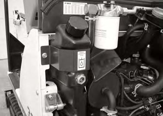
Figure PM-37
Warning
Always clean up spilled fuel or oil. Keep heat, flames, sparks or lighted tobacco away from fuel and oil. Failure to use care around combustibles can cause explosion or fire which can result in injury or death.
W-2103-1285
Hydraulic Fluid Chart

Figure PM-39
Open the tailgate. The fluid must be at the center of the sight gauge (Item 1) [Figure PM-37]
Remove oil fill cap (Item 2) [Figure PM-37]
Figure PM-38
Check the condition of the screen (Item 1) [Figure PM38] in the fill neck of the reservoir. The screen must be installed in fill neck when adding oil.
Use the correct hydraulic fluid shown in chart [Figure PM-39]
Add hydraulic fluid as needed to bring the level to the center of sight gauge (Item 1) [Figure PM-37]
Install the oil fill cap.
HYDRAULIC SYSTEM (CONT’D)
Removing And Replacing Hydraulic Filter
See the SERVICE SCHEDULE for the correct service interval. (See SERVICE SCHEDULE on Page PM-5)
Open the tailgate.
Figure PM-40
Remove the filter (Item 1) [Figure PM-40].
Clean the housing where the filter gasket makes contact.
Put clean hydraulic fluid on the gasket. Install the new filter and hand tighten only.
Start the engine. Run the excavator through the hydraulic functions. Stop the engine. Check the fluid level at the sight gauge (Item 2) [Figure PM-40] and add as needed. Check the filter area for leaks.
Removing And Replacing Hydraulic Fluid
See the SERVICE SCHEDULE for the correct service interval. (See SERVICE SCHEDULE on Page PM-5)
Retract the tracks fully.
Retract the arm and bucket cylinders. Lower the bucket to the ground and lower the blade. Stop the engine.


Open the tailgate.
Remove and replace the hydraulic filter.
HYDRAULIC SYSTEM (CONT’D)
Removing And Replacing Hydraulic Fluid (Cont’d)
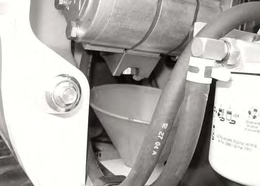
Figure PM-43
Remove the drain plug (Item 1) [Figure PM-43] from the pump fitting and drain the hydraulic fluid into the container.
Important
Fluid such as engine oil, hydraulic fluid, coolants, grease, etc. must be disposed of in an environmentally safe manner. Some regulations require that certain spills and leaks on the ground must be cleaned in a specific manner. See local, state and federal regulations for the correct disposal.
I-2067-0499
Important
If the fluid is being drained because of a system failure, remove and clean all hydraulic lines.
I-2045-0788
Install the drain plug.
Add fluid to the reservoir until it is at the center of the sight gauge (Item 1) [Figure PM-44]. (See HYDRAULIC SYSTEM on Page PM-25)
Run the excavator through the hydraulic functions. Stop the engine. Check the fluid level and add as needed.
Spark Arrestor Muffler
Cleaning Procedure
See the SERVICE SCHEDULE for the correct service interval. (See SERVICE SCHEDULE on Page PM-5)
Do not operate the excavator with a defective exhaust system.
Stop the engine. Open the tailgate.
Figure PM-45
Warning
When an engine is running in an enclosed area, fresh air must be added to avoid concentration of exhaust fumes. If the engine is stationary, vent the exhaust outside. Exhaust fumes contain odorless, invisible gases which can kill without warning.
W-2050-1285
Warning
Stop engine and allow the muffler to cool before cleaning the spark chamber. Wear safety goggles. Failure to obey can cause serious injury.
Warning
Never use machine in atmosphere with explosive dust or gases or where exhaust can contact flammable material. Failure to obey warnings can cause injury or death.
Remove the plug (Item 1) [Figure PM-45] from the bottom of the muffler.
Start the engine and run for about ten seconds while a second person, wearing safety glasses, holds a piece of wood over the outlet of the muffler. (The carbon deposits will be forced out of the muffler cleanout hole.)
Stop the engine. Install and tighten the plug.
Close the tailgate.
Warning
When the engine is running during service, the steering levers must be in neutral.

Failure to do so can cause injury or death.
W-2203-0595
Track Tension
NOTE: The wear of undercarriage parts vary with working conditions and types of soil conditions. Maintain the correct track tension by inspecting regularly. (See SERVICE SCHEDULE on Page PM-5) for the correct service interval.

Adjusting
Figure PM-46
Raise one side of the machine (approximately four inches) using the boom and arm as shown in [Figure PM-46]

Raise the blade fully and install jackstands under the blade and the track frame. Lower the machine until all machine weight is on the jackstands.

Stop the engine.
Warning
AVOID INJURY
Keep fingers and hands out of pinch points when checking the track tension.
W-2142-0903
Measure the rubber track sag at the middle track roller [Figure PM-47]. Do not get your fingers into pinch points between the track and the track roller. Use material of appropriate size to check the gap between the contact edge of the roller and top edge of the track guide lug [Figure PM-47] & [Figure PM-48]
TRACK TENSION (CONT’D)
Adjusting (Cont’d)
Figure PM-49
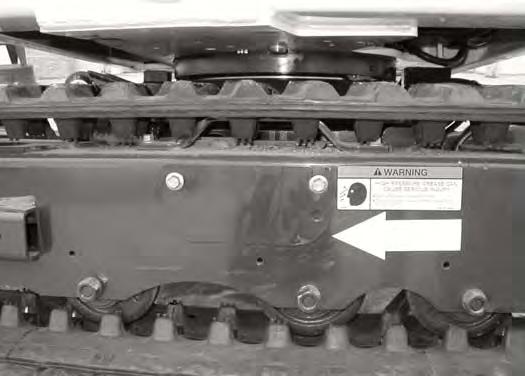
Warning
AVOID INJURY OR DEATH
Do not loosen the grease fitting more than one complete rotation. Also, be careful not to loosen any part other than the grease fitting. If the grease fitting or any part is loosened too much, it can fly off under high pressure. If the grease does not ooze smoothly, try moving the machine back and forth for a short distance.
Loosen its two bolts (Item 1) [Figure PM-49] from the cover. Pivot the cover downward.
Figure PM-50
Add grease to the fitting (Item 1) [Figure PM-50] until the track tension is correct.
If tension is too tight, loosen the bleed screw (Item 2) [Figure PM-50] (1 turn maximum) and let grease flow out of the bleed screw. When tension is correct, tighten the bleed screw.
Repeat the procedure for the other side.
If the track tension is still loose after adjusting to the mentioned limit, it indicates the track is worn. See your dealer for repairs.