2 minute read
TRACK FRAME EXPANSION Operation


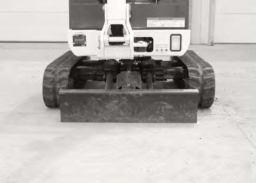
The excavator can be operated with the track frame retracted for transport on a trailer or to access narrow areas [Figure OI-37]
Push the Blade / Track Expansion switch (Item 1) [Figure OI-39] to the Blade position, “A”.
With the boom and arm positioned over the blade, lower the blade until the track is raised 4.0 - 6.0 inches (100150 mm) off the ground [Figure OI-39].
Rotate the upperstructure 180 degrees.
Expand the track frame for increased digging performance [Figure OI-38]
Important
To prevent wear and damage to the track, always lift the excavator before expanding or retracting the track frame.
I-2193-0599
Lower the boom and arm to raise the rear of the excavator until the track is 4.0 - 6.0 inches (100 - 150 mm) off the ground [Figure OI-40]


TRACK FRAME EXPANSION (CONT’D)
Operation (Cont’d)
Push the Blade / Track Expansion switch (Item 1) [Figure OI-41] to the Track Expansion position, “B”.
Important
To prevent wear and damage to the track, always lift the excavator before expanding or retracting the track frame.
Push the Blade / Track Expansion lever [Figure OI-42] forward to expand the track frame. Hold the lever forward until the track frame is fully expanded.
Pull the Blade / Track Expansion lever [Figure OI-42] back to retract the track frame. Hold the lever back until the track frame is fully retracted.
The track frame must be either in the fully expanded or fully retracted position when in use.
NOTE: Always return the Blade / Track Expansion switch to the Blade position “A” (Item 1) [Figure OI-43] during operation so that the track does not move when using the blade lever.


Raise the boom and arm to lower the rear of the excavator to the ground.
Rotate the upperstructure 180 degrees.
Raise the blade until the track is on the ground.
BOOM SWING PEDAL Operation


NOTE: The purpose of the boom swing pedal is to offset the boom with respect to the upperstructure for digging close to a structure [Figure OI-46].

Daily Inspection

DAILY INSPECTION (CONT’D)
Daily Inspection And Maintenance
Maintenance work must be done at regular intervals. Failure to do so will result in excessive wear and early failures. The Service Schedule [Figure OI-47] is a guide for correct maintenance of the Bobcat Excavator. It is located inside the tailgate of the excavator and also in this manual.
Check the following items before each day of operation:
•Engine oil level and for engine leaks
•Hydraulic fluid level and system for leaks
•Engine Air Filter, Check Air System for Damage or Leaks
•Engine Coolant Level, Check System for Damage or Leaks
•Operator Canopy or Cab (ROPS/TOPS) and mounting hardware
•Seat Belt and mounting hardware
•Check control console lockout(s)
•Clean engine area of any flammable material
•Track Tension
•Fuel Filter, Remove Trapped Water
•Loose or Broken Parts, Repair or replace as necessary
•Safety Treads and Safety Signs (Decals), Replace as necessary
•Cylinder and attachment pivot points
•Grease all pivot points
Warning
Operator must have instructions before operating the machine. Untrained operators can cause injury or death.
W-2001-0502
Fluids such as engine oil, hydraulic fluid, coolants, etc. must be disposed of in an environmentally safe manner. Some regulations require that certain spills and leaks on the ground must be cleaned in a specific manner. See local, state, and federal regulations for correct disposal.
Important
Pressure Washing Decals
•Never direct the stream at a low angle toward the decal that could damage the decal causing it to peel from the surface.
•Direct the stream at a 90 degree angle and at least 12 inches (300 mm) from the decal. Wash from the center of the decal toward the edges.
I-2226-0104