8 minute read
PRE-STARTING PROCEDURE (CONT’D)


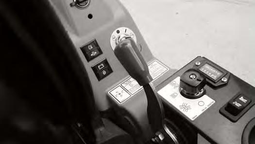
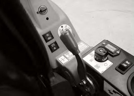
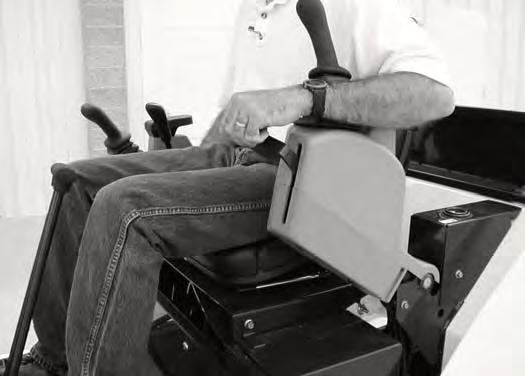
Control Console
Figure OI-55
Lower the control console(s) [Figure OI-55]
NOTE: The console(s) must be in the locked down position for the hydraulic control levers (joysticks) and traction system to operate.
NOTE: If the control lock switch does not deactivate the control levers (joysticks) when console is raised, see your Bobcat dealer for service.
STARTING THE ENGINE Key Switch
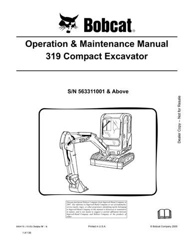
Warning
AVOID INJURY OR DEATH
•Fasten seat belt, start and operate only from the operator seat.
•Never wear loose clothing when working near machine.
W-2135-1188
Perform the PRE-STARTING PROCEDURE. (See PRESTARTING PROCEDURE on Page OI-23)
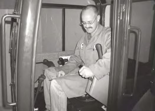
Figure OI-56
Put control levers (Item 1) [Figure OI-56] in the neutral position.
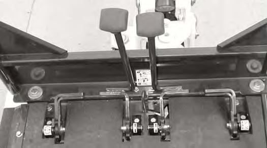
Figure OI-57
Move the engine speed control to low idle [Figure OI-57]
Warning
When an engine is running in an enclosed area, fresh air must be added to avoid concentration of exhaust fumes. If the engine is stationary, vent the exhaust outside. Exhaust fumes contain odorless, invisible gases which can kill without warning.
W-2050-1285
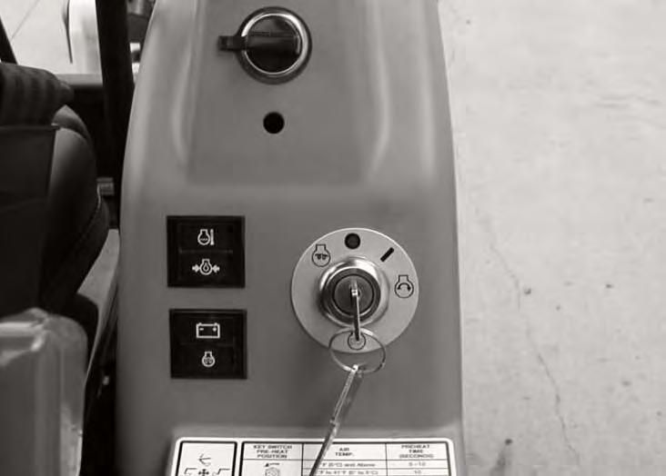
Figure OI-58
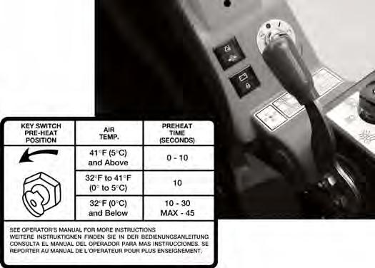
Turn the key to PREHEAT position (if required). (See Cold Temperature Starting on Page OI-27)
Turn the key to START [Figure OI-58] and release the key when the engine starts. It will return to the ON position.
Stop the engine if the warning lights and alarm do not go OFF. Check for the cause before starting the engine again.
Turn the key switch OFF to stop the engine.
Important
Do not engage the starter for longer than 15 seconds at a time. Longer use can damage the starter by overheating. Allow starter to cool for one minute before using starter again.
I-2034-0700
Warning
AVOID INJURY OR DEATH
•Engines can have hot parts and hot exhaust gas. Keep flammable material away.
•Do not use machines in atmosphere containing explosive gas.
W-2051-1086
STARTING THE ENGINE (CONT’D)
Cold Temperature Starting WARNING
Do not use ether with glow plug (preheat) systems. Explosion can result which can cause injury, death, or severe engine damage.
W-2071-0903
If the temperature is below freezing, perform the following to make starting the engine easier:
•Replace the engine oil with the correct type and viscosity for the anticipated starting temperature. (See ENGINE LUBRICATION SYSTEM on Page PM15)
•Make sure the battery is fully charged:
•Install an engine heater, available from your Bobcat Loader dealer.
NOTE: If the battery is discharged (but not frozen) a booster battery can be used to jump start the excavator. (See Using A Booster Battery (Jump Starting) on Page PM-23)
Important
Do not engage the starter for longer than 15 seconds at a time. Longer use can damage the starter by overheating. Allow starter to cool for one minute before using starter again.
Push the speed control lever fully forward [Figure OI-59].
Turn the key to PREHEAT [Figure OI-60]. The light (Item 1) [Figure OI-61] will come ON. Preheat the engine for 15 seconds maximum.
Turn the key to START [Figure OI-60] and release the key when the engine starts. It will return to the ON position.
When the engine speed increases, move the speed control lever to the low idle position.
Turn the key switch OFF to stop the engine [Figure OI60]
STARTING THE ENGINE (CONT’D)
Warming The Hydraulic System WARNING
During cold weather 32°F (0°C) and below, do not operate machine until the engine has run for at least five (5) minutes at less than half throttle. This warmup period is necessary. Do not operate controls during warm-up period. When temperatures are below -20°F (30°C), the hydraulic oil must be heated or kept warm. The hydraulic system will not get enough oil at low temperatures. Park the machine in an area where the temperature will be above 0°F (18°C), is possible.
W-2381-0700
Let the engine run for a minimum of 5 minutes to warm the engine and the hydraulic fluid before operating the excavator.
STOPPING THE ENGINE AND LEAVING THE EXCAVATOR
Procedure
Stop the machine on level ground. Lower the work equipment and the blade to the ground [Figure OI-62]
Turn the key switch OFF [Figure OI-64]
Disconnect the seat belt.
Remove the key from the switch to prevent operation of machine by unauthorized personnel.
Exit machine.
Move the speed control lever fully backward [Figure OI63]
Run the engine at idle speed for approximately 5 minutes to allow it to cool.
STOPPING THE ENGINE AND LEAVING THE EXCAVATOR (CONT’D)
Emergency Exits
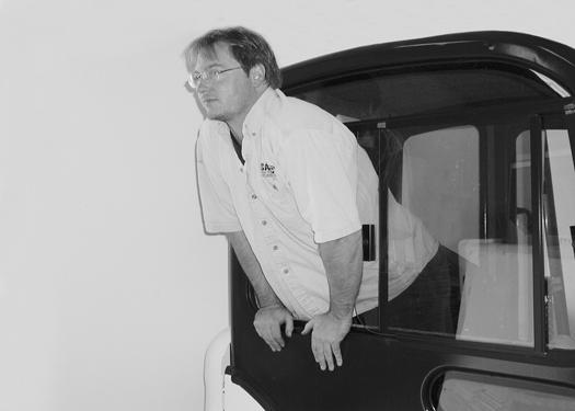
The right side rear window and the front window provide exits.
Right Side Rear Window
Figure OI-65
Slide the right side rear window to the front of the excavator and exit through the side window [Figure OI65].
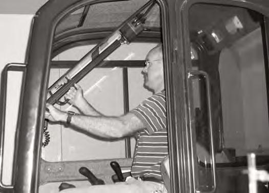
Front Window
Figure OI-66
Open the front window and exit [Figure OI-66]
NOTE:If the excavator has a Special Applications Kit installed, the front window is NOT an emergency exit.
Attachments
Installing And Removing The Attachment
Warning
AVOID INJURY OR DEATH
Stop the machine on a firm flat surface. When removing or installing attachments (such as a bucket), always have a second person in the operator’s seat, give clear signals and work carefully.
W-2140-0189
Install the fasteners (Item 1) [Figure OI-68]. Add grease to the pivot.
Removal
Park the excavator on a flat surface and put the bucket on the ground.
Remove the fasteners (Item 1) [Figure OI-68]
Remove the washers and the pivot pins (Item 1 and 3) [Figure OI-67].
Do not damage the dust seals in the arm.
Warning
Install the arm into the bucket, align the hole, install the pivot pin and washer (Item 1) [Figure OI-67]
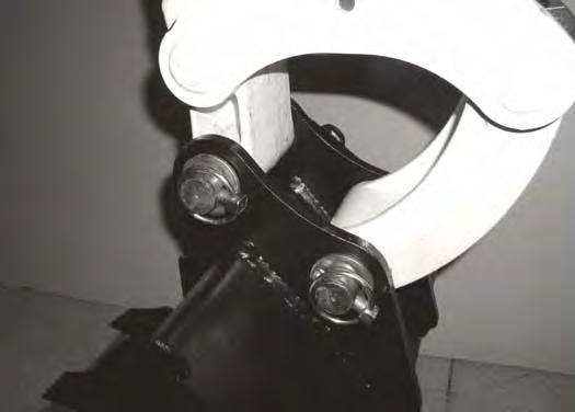
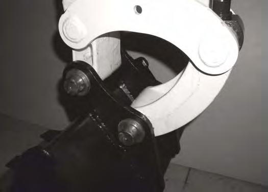
Install the link (Item 2) into the bucket, align the hole, install the pivot pin and washer (Item 3) [Figure OI-67]
Never use attachments or buckets which are not approved by Bobcat Company. Buckets and attachments for safe loads of specified densities are approved for each model. Unapproved attachments can cause injury or death.
OPERATING PROCEDURE Inspect The Work Area
Before beginning operation, inspect the work area for unsafe conditions.
Look for sharp drop-offs or rough terrain. Have underground utility lines (gas, water, sewer, irrigation, etc.) located and marked.
Remove objects or other construction material that could damage the excavator or cause personal injury.
Lowering The Work Equipment (Engine STOPPED)
The hydraulic control levers control the movement of the boom, arm, bucket and upperstructure slew functions.
Operating On Public Roads
When operating on a public road or highway, always follow local regulations. For example: A slow moving vehicle (SMV) sign, or direction signals may be required.
Check with utility companies for underground electrical, water, gas lines, etc. Work slowly in areas of underground utilities.
Run the engine at low idle speed to warm the engine and hydraulic system before operating the excavator.
Important
Machines warmed up with moderate engine speed and light load have longer life.
The joystick lock switch disengages the hydraulic control functions from the joysticks when the console(s) are raised [Figure OI-69].
NOTE: If the engine stops, the boom/bucket (attachments) can be lowered to the ground using hydraulic pressure in the accumulator.
The control console(s) must be in the locked down position, and the key switch in the ON position.
Use the control lever to lower the boom.
Lower the control console(s) to engage the hydraulic control functions of the joysticks [Figure OI-69].
OPERATING PROCEDURE (CONT’D)
Lifting A Load
Do not exceed the Rated Lift Capacity. (See LIFT CHART - STANDARD ARM (7111724) on Page MST-4) or (See LIFT CHART - LONG ARM (7111984) on Page MST-6)
Warning
AVOID INJURY OR DEATH
Do not exceed rated lift capacity. Excessive load can cause tipping or loss of control.
W-2374-0500
Extend the bucket cylinder completely and lower the boom to the ground. Stop the engine.
Wrap the chain assembly around the bucket mounting plate.
Excavating
Lower the blade to provide stability.
Figure OI-71
Make sure the load is evenly weighted and centered on the lifting chain, and is secured to prevent the load from shifting [Figure OI-70].
Lift and position the load. Once the load is in position and tension is removed from the lift chain (secondary lift system), remove the secondary lift system.
Warning
AVOID INJURY OR DEATH
Check area to be excavated for overhead or underground lines such as electrical, gas, oil, water, etc. CALL 1-888-258-0808 and consult local utilities before digging. Extreme caution must be used in areas where utility lines are present.
W-2116-0903
Extend the arm, lower the boom, and open the bucket [Figure OI-71].
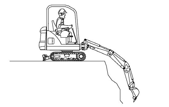
Figure OI-72
Retract the arm, while lowering boom and curling the bucket [Figure OI-72].
OPERATING PROCEDURE (CONT’D)
Excavating (Cont’d)
Raise the boom, retract the arm and curl the bucket [Figure OI-73]
Rotate the upperstructure. (See Upperstructure Slew Lock on Page OI-5)
NOTE: Do not allow the bucket teeth to contact the ground when slewing the upperstructure.
Warning
Keep all bystanders 20 feet (6 m) away from equipment when operating. Contact with moving parts, a trench cave-in or flying objects can cause injury or death.
W-2119-0788
Do not dig under the excavator [Figure OI-75]
Do not use the bucket as a breaker or pile driver. It is better to excavate hard or rocky ground after breaking it with other equipment. This will reduce damage to the excavator.
Do not move the excavator while the bucket is in the ground.
OPERATING PROCEDURE (CONT’D)
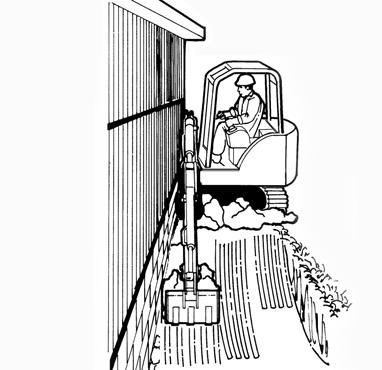
Boom Swing
Slew the upperstructure, offset the boom to the left [Figure OI-76], center [Figure OI-77] and right [Figure OI-78] to dig a square hole the width of the machine without repositioning the excavator.
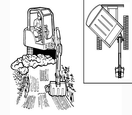
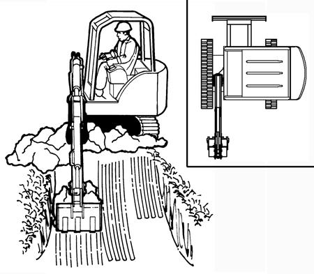
The boom offset allows the operator to dig close to buildings and other structures [Figure OI-79]
OPERATING PROCEDURE (CONT’D)
Backfilling
Figure OI-80
Use the blade to backfill the trench or hole after excavating [Figure OI-80]
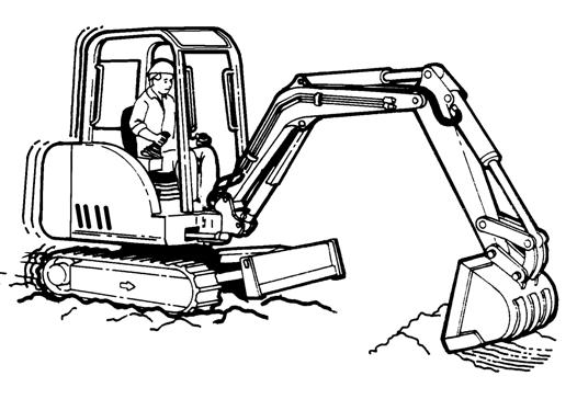
Driving The Excavator
When operating on uneven ground, operate as slow as possible and avoid sudden changes in direction.
Avoid traveling over objects such as rocks, trees, stumps, etc.
When working on wet or soft ground, put planks on the ground to provide a solid base to travel on and prevent the excavator from getting stuck.
If one or both tracks have become stuck in soft or wet ground, raise one track at a time by turning the upperstructure and pushing the bucket against the ground [Figure OI-81]
Put planks under the tracks and drive the excavator to dry ground.
The bucket may also be used to pull the excavator. Raise the blade, extend the arm and lower the boom. Operate the boom and arm in a digging manner [Figure OI-82]
OPERATING PROCEDURE (CONT’D)
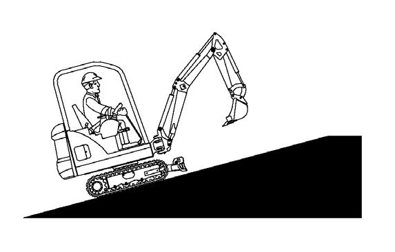
Operating On Slopes
Warning
AVOID INJURY OR DEATH
•Do not travel across or up slopes that are over 15 degrees.
•Do not travel down or back up slopes that exceed 25 degrees.
•Look in the direction of travel.
When going down a slope, control the speed with the steering levers and the speed control lever.
Warning
AVOID INJURY OR DEATH
•Avoid steep areas or banks that could break away.
•Keep boom centered and attachments as low as possible when traveling on slopes or in rough conditions. Look in the direction of travel.
•Always fasten seat belt.
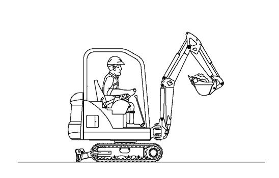
When traveling down or backing up grades that exceed 15 degrees, put the machine in the position shown, and run the engine slowly [Figure OI-83].
Operate as slow as possible and avoid sudden changes in lever direction.
Avoid traveling over objects such as rocks, trees, stumps, etc.
Stop the machine before moving the upper equipment controls. Never allow the blade to strike a solid object. Damage to the blade or hydraulic cylinder can result.
When traveling up slopes or on side slopes that are 15 degrees or less, position the machine as shown and run the engine slow [Figure OI-84] & [Figure OI-85]