ADJUSTING
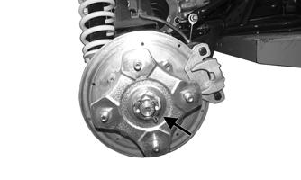
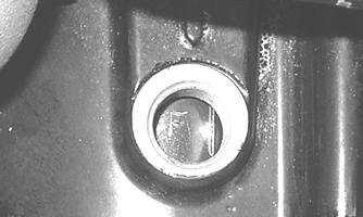
Valve/Tappet Clearance To check and adjust valve/tappet clearance, use the following procedure: 1. Remove the timing inspection plug; then remove the tappet covers and spark plug (for more detailed information, see Engine/Transmission — Servicing Top-Side Components). 2. Rotate the crankshaft to the TDC position on the compression stroke.
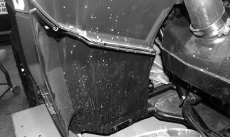
NOTE: The seat, storage compartment cover assembly, compartment box, air filter/filter housing, and left-side/right-side splash panels must be removed for this procedure.
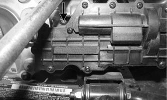
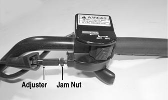
A. Place Valve Clearance Adjuster onto the jam nut securing the tappet adjuster screw; then rotate the valve adjuster dial clockwise until the end is seated in the tappet adjuster screw. B. While holding the valve adjuster dial in place, use the valve adjuster handle and loosen the jam nut; then rotate the tappet adjuster screw clockwise until friction is felt. C. Align the valve adjuster handle with one of the marks on the valve adjuster dial. D. While holding the valve adjuster handle in place, rotate the valve adjuster dial counterclockwise until proper valve/tappet clearance is attained. NOTE: Refer to the appropriate specifications in CHECKING for the proper valve/tappet clearance. NOTE: Rotating the valve adjuster dial counter-
clockwise will open the valve/tappet clearance by 0.05 mm (0.002 in.) per mark.
GZ063
NOTE: At this point, the rocker arms and adjuster
screws must not have pressure on them.
E. While holding the adjuster dial at the proper clearance setting, tighten the jam nut securely with the valve adjuster handle.
CHECKING
3. Install the spark plug and timing inspection plug.
Using a feeler gauge, check each valve/tappet clearance. If clearance is not within specifications, loosen the jam nut and rotate the tappet adjuster screw until the clearance is within specifications. Tighten each jam nut securely after completing the adjustment.
4. Place the tappet covers into position making sure the proper cap screws are with the proper cover. Tighten the cap screws securely.
CAUTION The feeler gauge must be positioned at the same angle as the valve and valve adjuster for an accurate measurement of clearance. Failure to measure the valve clearance accurately could cause valve component damage. 570/700
VALVE/TAPPET CLEARANCE 0.08-0.12 mm (0.003-0.005 in.) — Intake 0.13-0.17 mm (0.005-0.007 in.) — Exhaust
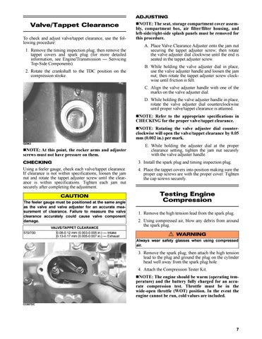
Testing Engine Compression 1. Remove the high tension lead from the spark plug. 2. Using compressed air, blow any debris from around the spark plug.
! WARNING Always wear safety glasses when using compressed air.
3. Remove the spark plug; then attach the high tension lead to the plug and ground the plug on the cylinder head well away from the spark plug hole. 4. Attach the Compression Tester Kit. NOTE: The engine should be warm (operating temperature) and the battery fully charged for an accurate compression test. Throttle must be in the wide-open throttle (WOT) position. In the event the engine cannot be run, cold values are included. CC007DC
7