9 minute read
General Information/Foreword

BRAKE COMPONENTS
Brake Disc Hub 15 20 Brake Hose Frame 12 16 Brake Hose Caliper/Cylinder 20 27 Master Cylinder Master Cylinder Clamp 6 8 Master Cylinder Frame 6 8 Caliper Knuckle 20 27 Brake Clip A-Arm 40 4.5 in.-lb Brake Pedal Pedal Axle 25 34
MISCELLANEOUS COMPONENTS
Radiator Frame 12 16 Coil Frame 10 1.1 in.-lb Front Bumper Frame Mount 20 27 Front Bumper Frame 35 47 Skid Plate Frame 6 8 Rack Frame/Rack Mount 13 18 Taillight Rear Fascia 13 18 Gas Tank Mounting Bracket Frame 8 11 Rear Fascia Frame 20 2.5 in.-lb Side Panel/Console Frame 8 11 Front Fascia Front Bumper (lower) 8 11 Front Fascia Front Bumper (upper) 5 7
SUSPENSION COMPONENTS
A-Arm Frame 50 68 Knuckle Ball Joint 35 47 Shock Absorber Frame/A-Arm 50 68 Knuckle A-Arm 50 68 Sway Bar Frame 35 47 Sway Bar Link Lower A-Arm 25 33
DRIVE TRAIN COMPONENTS
Front Differential* Frame/Differential 38 52 Bracket Oil Fill Plug Front Differential/Rear 16 22 Drive Wheel (Steel) Hub 40 54 Wheel (Aluminum w/black nuts)Hub 60 81 Wheel (Aluminum w/chrome Hub 80 108 nuts) Rear Gear Case* Frame 38 52 Hub Axle 200 272 Oil Drain Plug Front Differential/Rear 45 5 Drive in.-lb Pinion Housing (Existing) Differential Housing 22 30 Pinion Housing (New) Differential Housing 28 38 Differential Housing Cover*** Differential Housing 22 30 (Existing) Differential Housing Cover*** Differential Housing 28 38 (New) Thrust Button** Gear Case Cover 8 11 Output Shaft Flange 20 27
ENGINE/TRANSMISSION
Clutch Shoe** (570) Crankshaft 221 300 Driven Pulley** (570) Driveshaft 60 81 Driven Pulley** (700) Driveshaft 162 220 Ground Wire Engine 8 11 Magneto Cover Crankcase 9.5 13 Speed Sensor Housing Crankcase 8.5 11.5 (570/700) Oil Drain Plug Engine 16 22 Clutch Cover/Housing Crankcase 9.5 13 Cam Sprocket** Camshaft 10 14 Cylinder Crankcase 8 11 V-Belt Cover Clutch Cover/Housing 45 5 in.-lb
Movable Drive Face** (570) Centrifugal Clutch Housing 162 220
Starter Clutch** Flywheel 26 35 Output Shaft Nut** Output Shaft 59 80 Valve Cover Cylinder Head 8.5 11.5 Stator Coil (New) Magneto Cover 13 18 Stator Coil (Existing) Magneto Cover 11.5 15 Drive Clutch Nut (700) Drive Clutch 79.6108 Drive Clutch Bolt (700) Crankshaft 59 80 Oil Strainer Cap Crankcase 54 6 in.-lb Rotor/Flywheel Crankshaft 107 145 Oil Pump** Crankcase 8.5 11.5 Water Pump/Housing Magneto Cover 8.5 11.5 Crankcase Half (6 mm) Crankcase Half 10 14 Crankcase Half (8 mm) Crankcase Half 21 28 Starter Motor Crankcase 10 14 Shift Lever Shift Axle 8 11 Engine Mounting Through-Bolt Frame 35 47 Output Yoke Nut** Output Shaft 200 270 Shift Cam Plate Shift Cam Shaft 8.5 11.5 Cylinder Head (Bolt) Crankcase (step 1) 20 27 (step 2) 30 41 (final) 37 50 Cylinder Head Nut (6 mm) Cylinder 10 14 Cylinder Head Nut (8 mm) Cylinder 19 25 Shift Cam Stopper Crankcase 8.5 11.5 Crankshaft Bushing Crankshaft 25 34 Oil Pump Drive Gear** Crank Balancer Shaft 63 85 Outer Magneto Cover Left-Side Cover 8.5 11.5 Secondary Shaft Bearing Crankcase Half 25 34 Housing * w/Blue Loctite #243 ** w/Red Loctite #271 *** w/Green Loctite #609
Torque Conversions (ft-lb/N-m)
Gasoline — Oil — Lubricant
ft-lb N-m ft-lb N-m ft-lb N-m ft-lb N-m 1 1.4 26 35.4 51 69.4 76 103.4 2 2.7 27 36.7 52 70.7 77 104.7 3 4.1 28 38.1 53 72.1 78 106.1 4 5.4 29 39.4 54 73.4 79 107.4 5 6.8 30 40.8 55 74.8 80 108.8 6 8.2 31 42.2 56 76.2 81 110.2 7 9.5 32 43.5 57 77.5 82 111.5 8 10.9 33 44.9 58 78.9 83 112.9 9 12.2 34 46.2 59 80.2 84 114.2 10 13.6 35 47.6 60 81.6 85 115.6 11 15 36 49 61 83 86 117 12 16.3 37 50.3 62 84.3 87 118.3 13 17.7 38 51.7 63 85.7 88 119.7 14 19 39 53 64 87 89 121 15 20.4 40 54.4 65 88.4 90 122.4 16 21.8 41 55.8 66 89.8 91 123.8 17 23.1 42 57.1 67 91.1 92 125.1 18 24.5 43 58.5 68 92.5 93 126.5 19 25.8 44 59.8 69 93.8 94 127.8 20 27.2 45 61.2 70 95.2 95 129.2 21 28.6 46 62.6 71 96.6 96 130.6 22 29.9 47 63.9 72 97.9 97 131.9 23 31.3 48 65.3 73 99.3 98 133.3 24 32.6 49 66.6 74 100.6 99 134.6 25 34 50 68 75 102 100 136
FILLING GAS TANK ! WARNING
Always fill the gas tank in a well-ventilated area. Never add gasoline to the ATV gas tank near any open flames or with the engine running. DO NOT SMOKE while filling the gas tank.
Since gasoline expands as its temperature rises, the gas tank must be filled to its rated capacity only. Expansion room must be maintained in the tank particularly if the tank is filled with cold gasoline and then moved to a warm area.
Tighten the gas tank cap securely after filling the tank.
RECOMMENDED GASOLINE The recommended gasoline to use is 87 minimum octane regular unleaded. In many areas, oxygenates are added to the gasoline. Oxygenated gasolines containing up to 10% ethanol or 5% methanol are acceptable gasolines. When using ethanol-blended gasoline, it is not necessary to add a gasoline antifreeze since ethanol will prevent the accumulation of moisture in the fuel system.
! WARNING
Do not overflow gasoline when filling the gas tank. A fire hazard could materialize. Always allow the engine to cool before filling the gas tank.
! WARNING
Do not over-fill the gas tank.
CAUTION
Do not use white gas. Only approved gasoline additives should be used.
RECOMMENDED ENGINE/ TRANSMISSION OIL CAUTION
Any oil used in place of the recommended oil could cause serious engine damage. Do not use oils which contain graphite or molybdenum additives. These oils can adversely affect clutch operation. Also, not recommended are racing, vegetable, non-detergent, and castor-based oils.
The recommended oil to use is ACX All Weather synthetic which has been specifically formulated for use in this engine. Although ACX All Weather synthetic engine oil is the only oil recommended for use in this engine, use of any API-certified SM 0W-40 oil is acceptable.
OILCHARTJ
RECOMMENDED FRONT DIFFERENTIAL/REAR DRIVE LUBRICANT The recommended lubricant is SAE-approved 80W-90 hypoid. This lubricant meets all of the lubrication requirements of the front differential and rear drive.
CAUTION
Any lubricant used in place of the recommended lubricant could cause serious front differential/rear drive damage.
Preparation for Storage
CAUTION
Prior to storing the ATV, it must be properly serviced to prevent rusting and component deterioration.
The manufacturer recommends the following procedure to prepare the ATV for storage: 1.Clean the ATV thoroughly by washing dirt, oil, grass, and other foreign matter from the entire ATV.
Allow the ATV to dry thoroughly. DO NOT get water into any part of the engine or air intake. 2.Either drain the gas tank or add a fuel stabilizer to the gas in the gas tank. 3.Clean the interior of the air filter housing. 4.Plug the hole in the exhaust system with steel wool. 5.Apply light oil to the upper steering post bushing and plungers of the shock absorbers. 6.Tighten all nuts, bolts, cap screws, and screws. Make sure rivets holding components together are tight.
Replace all loose rivets. Care must be taken that all calibrated nuts, cap screws, and bolts are tightened to specifications. 7.Fill the cooling system to the bottom of the stand pipe in the radiator neck with properly mixed coolant. 8.Disconnect the battery cables (negative cable first); then remove the battery, clean the battery posts and cables, and store in a clean, dry area. NOTE: For storage, use a battery maintainer or make sure the battery is fully charged (see Battery section in this manual). 9.Store the ATV indoors in a level position.
CAUTION
Avoid storing outside in direct sunlight and avoid using a plastic cover as moisture will collect on the ATV causing rusting.
Preparation after Storage
Taking the ATV out of storage and correctly preparing it will ensure many hours of trouble-free riding. The manufacturer recommends the following procedure to prepare the ATV: 1.Clean the ATV thoroughly. 2.Remove steel wool from the exhaust system. 3.Check all control wires and cables for signs of wear or fraying. Replace if necessary. 4.Change the engine/transmission oil and filter. 5.Check the coolant level and add properly mixed coolant as necessary. 6.Charge the battery; then install. Connect the battery cables making sure to connect the positive cable first.
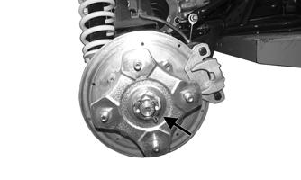
7.Check the entire brake systems (fluid level, pads, etc.), all controls, headlights, taillight, brake light, and headlight aim; adjust or replace if necessary. 8.Check the tire pressure. Inflate to recommended pressure as necessary. 9.Tighten all nuts, bolts, cap screws, and screws making sure all calibrated nuts, cap screws, and bolts are tightened to specifications. 10.Make sure the steering moves freely and does not bind. 11.Check the spark plug. Clean or replace as necessary. 12.Check the air filter and the air filter housing. Clean or replace as necessary.
CAUTION
Before installing the battery, make sure the ignition switch is in the OFF position.
Periodic Maintenance/Tune-up
Tighten all nuts, bolts, and cap screws. Make sure rivets holding components together are tight. Replace all loose rivets. Care must be taken that all calibrated nuts, bolts, and cap screws are tightened to specifications (see General Information/Foreword). It is advisable to lubricate certain components periodically to ensure free movement. Apply light oil to the components using the following list as reference:
A.Throttle Lever Pivot
B.Brake Lever Pivot
C.Auxiliary Brake Pedal Pivot NOTE: The manufacturer recommends the use of new gaskets, lock nuts, and seals, and lubricating all internal components when servicing the engine/transmission. SPECIAL TOOLS A number of special tools must be available to the technician when performing service procedures in this section. NOTE: When indicated for use, each special tool will be identified by its specific name, as shown in the chart below, and capitalized.
Description p/n
Compression Tester Kit Common Tool Oil Filter Wrench Common Tool Spanner Wrench 0444-240 Valve Clearance Adjuster 0444-255
NOTE: Special tools are available from the Service Department.
Air Filter
1.Remove the seat; then remove the clips securing the air filter housing cover.
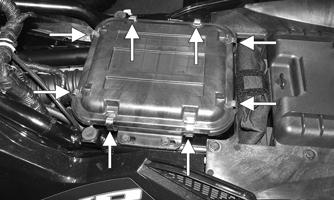

XR002A
2.Loosen the clamp securing the air filter to the inside of the housing; then remove the filter.
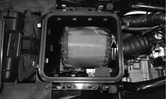
XR029A
3.Carefully remove the pre-filter from the air filter. If the air filter is dirty, it must be replaced.

XR049
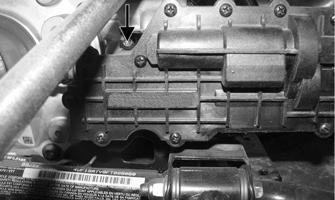
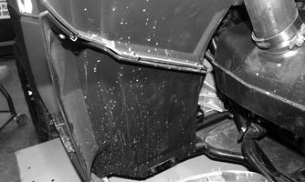
4.Using an air hose, clean the pre-filter. 5.Slide the pre-filter over the closed end of the new filter and install into the housing. Tighten the clamp securely. 6.Install the air filter housing cover and secure with the clips. 7.Install the seat. CHECKING AND CLEANING DRAINS 1.Inspect the drains beneath the main housing for water/oil and for proper sealing.
XR489
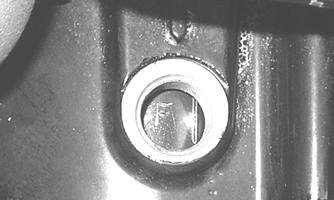
2.Replace any drain that is cracked or shows any signs of hardening or deterioration.
CAUTION