11 minute read
Fuel/Lubrication/Cooling

INSTALLING 1.Install the throttle body into the intake pipe and secure with the clamp. Tighten securely. 2.Install the air filter housing boot and secure with the two hose clamps. 3.Connect the four electrical connectors to the throttle body components. 4.Connect the throttle cable to the throttle body and adjust throttle cable free-play (see Throttle Cable
Free-Play in this section); then connect the gasline hose. 5.Install the actuator cover to the throttle body and secure with the two screws. NOTE: The longer screw goes on top. 6.Connect the battery (positive cable first); then install the side panels and seat making sure it locks securely in place. NOTE: If the throttle body, ECM, TPS, or ISC are replaced, the EFI system must be synchronized. Use the following procedure: 1.With the key off, depress the throttle lever to Wide
Open Throttle (WOT). 2.Place the ignition key in the ON position and wait for 10 seconds. 3.Release the throttle lever and wait an additional 10 seconds. 4.Turn the key to the OFF position and allow the gauge to shut off.
Throttle Cable Free-Play
To adjust the throttle cable free-play, follow this procedure. 1.Slide the rubber boot away; then loosen the jam nut from the throttle cable adjuster.
CF297A
2.Turn the adjuster until the throttle cable has proper free-play of 3-6 mm (1/8-1/4 in.) at the lever. 3.Tighten the jam nut against the throttle cable adjuster securely; then slide the rubber boot over the adjuster. ! WARNING
Whenever any maintenance or inspection is made on the fuel system during which there may be fuel leakage, there should be no welding, smoking, open flames, etc., in the area.
REMOVING 1.Remove the seat and side panels; then remove the rear body panel/rack. 2.Disconnect the fuel pump connector and gasline hose from the fuel pump.

XR124A
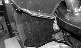
3.Remove the cable ties securing the vent hose to the frame. 4.Remove the two cap screws securing the gas tank mounting tab to the frame.
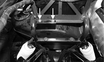
XR126A
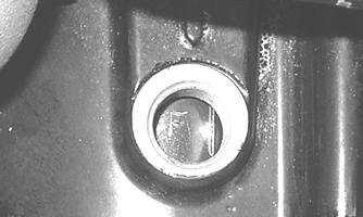
5.Remove the master cylinder from the mounting bracket; then remove the mounting bracket from the frame.
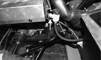
XR125A
NOTE: Using an appropriate tool, pry the tab of the master cylinder mounting bracket from the gas tank.
XR132A
6.Remove the battery cover; then disconnect the battery (negative cable first). 7.Remove the battery tray; then slide the gas tank out the left side of the vehicle. CLEANING AND INSPECTING 1.Clean all gas tank components with parts-cleaning solvent. 2.Inspect all hoses for cracks or leaks. 3.Inspect tank cap and tank for leaks, holes, and damaged threads. 4.Remove the fuel level sensor/fuel pick-up assembly and inspect the fuel level sensor and fuel screen. NOTE: If the fuel level sensor has failed or may be faulty, see Electrical System — EFI Sensors/Components. INSTALLING 1.Slide the gas tank into the vehicle from the left side. 2.Secure the master cylinder mounting bracket to the frame; then secure the master cylinder to the mounting bracket. Tighten the master cylinder nut to 12 ft-lb (16.3 N-m). NOTE: Ensure the tab of the mounting bracket is in place on the gas tank. 3.Secure the vent hose to the frame with cable ties (as noted during removing), then connect the gasline hose and fuel pump connector. 4.Secure the gas tank mounting tab to the frame using the existing cap screws. Tighten to 8 ft-lb (10.9
N-m). 5.Install the battery tray and secure with the mounting clips and Torx-head screw. Tighten the screw securely. 6.Install the battery and connect the battery cables (positive cable first); then install the battery cover. 7.Install the rear body panel/rack; then install the side panels and seat.
Oil Pump
TESTING OIL PUMP PRESSURE NOTE: The engine must be warmed up to the specified temperature for this test. 1.Connect the Tachometer to the engine or utilize the
LCD (if equipped). 2.Connect the Oil Pressure Test Kit to the oil pressure test port.

XR136A
NOTE: Some oil seepage may occur when installing the oil pressure gauge. Wipe up oil residue with a cloth.
3.Start the engine and run at 3000 RPM. With the oil temperature at 140° F (60° C), the oil pressure gauge must read as specified as follows:
570/700 1.2-1.5 kg/cm2 (17-21 psi)
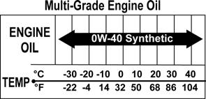
NOTE: If the oil pressure is lower than specified, check for low oil level, or defective oil pump. NOTE: If the oil pressure is higher than specified, check for too heavy engine oil weight (see General Information/Foreword), clogged oil passage, clogged oil filter, or improper installation of the oil filter.
Liquid Cooling System
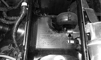
Checking/Filling 1.Remove the rubber access plug from the front fender.
XR477
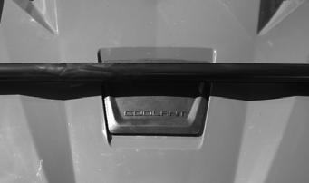
2.Carefully rotate the radiator cap counterclockwise to release pressure; then remove the cap.

XR478
3.Add coolant as necessary; then install the radiator cap and access plug. NOTE: Use a good quality, biodegradable glycol-based, automotive-type antifreeze. When filling the cooling system, use a coolant/water mixture which will satisfy the coldest anticipated weather conditions of the area in accordance with the coolant manufacturer’s recommendations.
! WARNING
Never check the coolant level when the engine is hot or the cooling system is under pressure.
CAUTION
After operating the ATV for the initial 5-10 minutes, stop the engine, allow the engine to cool down, and check the coolant level. Add coolant as necessary.
While the cooling system is being filled, air pockets may develop; therefore, run the engine for five minutes after the initial fill, shut the engine off, and then fill the cooling system to the bottom of the stand pipe in the radiator neck.
RADIATOR Removing 1.Drain the coolant at the engine. 2.Remove the front body panel/rack. 3.Remove the upper and lower coolant hoses. 4.Remove the cap screws and nuts securing the radiator to the frame. 5.Disconnect the fan wiring from the main wiring harness; then remove the radiator/fan assembly and account for the grommets and collars. 6.Remove the fan/fan shroud assembly from the radiator. Cleaning and Inspecting 1.Flush the radiator with water to remove any contaminants. 2.Inspect the radiator for leaks and damage. 3.Inspect all hoses for cracks and deterioration. 4.Inspect all fasteners and grommets for damage or wear. Installing 1.Position the fan/fan shroud assembly on the radiator; then secure with existing hardware. 2.Place the radiator with grommets and collars into position on the frame; then install the cap screws and nuts. Tighten to 12 ft-lb (16.3 N-m). 3.Install the upper and lower coolant hoses; then secure with hose clamps.

AF734D
4.Install the front body panel/rack. 5.Fill the cooling system with the recommended amount of antifreeze (see Periodic Maintenance/Tune-up). Check for leakage. 6.Connect the fan wiring to the main wiring harness. THERMOSTAT Removing 1.Drain approximately one quart of coolant from the cooling system. 2.Remove the two cap screws securing the thermostat housing to the cylinder head. Account for an O-ring and a thermostat.
Inspecting 1.Inspect the thermostat for corrosion or spring damage. 2.Using the following procedure, inspect the thermostat for proper operation:
A.Suspend the thermostat in a container filled with water.
B.Heat the water and monitor the temperature with a thermometer.
C.The thermostat should start to open at 160-187° F (71-86° C).
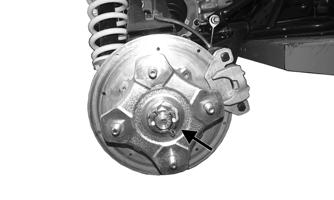
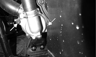
D.If the thermostat does not open, it must be replaced. 3.Inspect all coolant hoses, connections, and clamps for deterioration, cracks, and wear. NOTE: All coolant hoses and clamps should be replaced every four years or 4000 miles (6400 km). Installing 1.Place the thermostat and O-ring into the thermostat housing; then secure the thermostat housing to the cylinder head with the two cap screws. 2.Fill the cooling system with the recommended amount of antifreeze (see Periodic Maintenance/Tune-up). Check for leakage. COOLING FAN Removing 1.Remove the radiator (see RADIATOR in this sub-section). 2.Remove the fan assembly from the radiator. Installing 1.Position the fan assembly on the radiator; then secure with existing hardware. NOTE: The fan wiring must be in the upper-right position. 2.Install the radiator. WATER PUMP NOTE: On the 570/700, the water pump is only serviceable as an assembly. Removing 1.Remove the radiator cap; then remove the water pump drain and drain the coolant.

XR151A
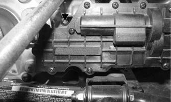
2.Drain the oil from the engine/transmission. 3.Remove the left side engine cover. 4.Loosen the hose clamps and slide the clamps away from the hose ends approximately 2 in. (5 cm); then remove both hoses from the water pump. 5.Remove the two cap screws securing the water pump to the engine; then remove the water pump.
XR151C
Installing 1.Secure the water pump to the engine with the two cap screws tightened securely. 2.Connect the two coolant hoses to the water pump and secure with the clamps. Tighten securely. 3.Install the left side engine cover. 4.Fill the engine/transmission with the proper amount of recommended oil. 5.Fill the cooling system with the proper amount of recommended coolant (see Periodic Maintenance/Tune-up). Check for leaks.
Troubleshooting
Problem: Starting impaired Condition Remedy
1. Battery discharged or defective 1.Test, charge, and/or replace battery 2. Gas contaminated 2.Drain gas tank and fill with clean gas 3. Air filter/housing contaminated 3.Clean or replace air filter/housing or replace
Problem: Idling or low speed impaired Condition Remedy
1. Gas contaminated 1.Drain gas tank and fill with clean gas 2. TPS out of adjustment 2.Adjust TPS 3. Air filter/housing contaminated 3.Clean or replace air filter/housing or replace 4. ISC malfunction 4.Inspect/replace ISC
Problem: Medium or high speed impaired Condition Remedy
1. Gas contaminated 1.Drain gas tank and fill with clean gas 2. Air filter/housing contaminated 2.Clean or replace air filter/housing or replace
Electrical System
The electrical connections should be checked periodically for proper function. TESTING ELECTRICAL COMPONENTS All electrical tests should be made using the CATT II or the Fluke Model 77 Multimeter. The CATT II can return data for certain components which are identified at the beginning of their respective sub-section. If any other type of meter is used, readings may vary due to internal circuitry. When troubleshooting a specific component, always verify first that the fuse(s) are good, that the LED(s) are good, that the connections are clean and tight, that the battery is fully charged, and that all appropriate switches are activated. NOTE: For absolute accuracy, all tests should be made at room temperature of 68° F (20° C). NOTE: Certain components and sensors can be checked by using the EFI diagnostic system and digital gauge (see EFI Diagnostic System in this section for more information). SPECIAL TOOLS A number of special tools must be available to the technician when performing service procedures in this section. Refer to the current Special Tool Catalog for the appropriate tool description. NOTE: When indicated for use, each special tool will be identified by its specific name, as shown in the chart below, and capitalized.
Description p/n
Diagnostic Harness 0486-219 Fluke Model 77 Multimeter Common Tool Fuel Pressure Tester 0644-587 MaxiClips Common Tool Tachometer Common Tool Timing Light Common Tool
NOTE: Special tools are available from the Service Department.
Battery
Component data can be retrieved using the CATT II. Utilize the Sensor Data screen.
NOTE: Preliminary checks may be performed on this component using the diagnostic mode on the LCD gauge (see EFI Diagnostic System in this section).
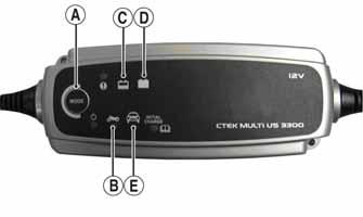
6.If using the CTEK Multi US 800, there are no further buttons to push. If using the CTEK Multi US 3300, press the Mode button (A) at the left of the charger until the Maintenance Charge Icon (B) at the bottom illuminates. The Normal Charge Indicator (C) should illuminate on the upper portion of the battery charger.
After being in service, batteries require regular cleaning and recharging in order to deliver peak performance and maximum service life. The following procedure is recommended for cleaning and maintaining a sealed battery. Always read and follow instructions provided with battery chargers and battery products. NOTE: Refer to all warnings and cautions provided with the battery or battery maintainer/charger. Loss of battery charge may be caused by ambient temperature, ignition OFF current draw, corroded terminals, self discharge, frequent start/stops, and short engine run times. Frequent winch usage, snowplowing, extended low RPM operation, short trips, and high amperage accessory usage are also reasons for battery discharge. Maintenance Charging NOTE: It is recommended to use the CTEK Multi US 800 or the CTEK Multi US 3300 for battery maintenance charging. Maintenance charging is required on all batteries not used for more than two weeks or as required by battery drain.

800E
1.When charging a battery in the vehicle, be sure the ignition switch is in the OFF position. 2.Clean the battery terminals with a solution of baking soda and water. NOTE: The sealing strip should NOT be removed and NO fluid should be added.
3.Be sure the charger and battery are in a well-ventilated area. Be sure the charger is unplugged from the 110-volt electrical outlet. 4.Connect the red terminal lead from the charger to the positive terminal of the battery; then connect the black terminal lead of the charger to the negative terminal of the battery. NOTE: Optional battery charging adapters are available from your authorized dealer to connect directly to your vehicle from the recommended chargers to simplify the maintenance charging process. Check with your authorized dealer for proper installation of these charging adapter connectors. 5.Plug the battery charger into a 110-volt electrical outlet.