5. Tighten the remaining cap screws; then connect the electrical plug to the main harness. 6. Turn the ignition switch to the ON position and check the operation by shifting the drive select switch several times. 7. Secure the wiring harness to the frame with a nylon cable tie.
Front Differential XR164A
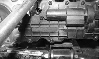
INSTALLING NOTE: Make sure to properly align the differential lock actuator lever with the hole in the differential lock plunger.
1. Lubricate the O-rings on the actuator; then ensure that all mounting surfaces are clean and free of debris. 2. Align the actuator with the selector shaft and slide it forward onto the shaft taking care to engage the cap screw in the slot of the front mounting tab.
REMOVING DIFFERENTIAL
1. Secure the ATV on a support stand to elevate the wheels.
! WARNING Make sure the ATV is solidly supported on the support stand to avoid injury.
2. Remove the drain plug and drain the gear lubricant into a drain pan; then reinstall the plug and tighten to 45 in.-lb (5 N-m).
ATV0082A XR164A
3. While holding the actuator firmly forward, tighten the front cap screw to hold the actuator in place; then install but do not tighten the two remaining cap screws.
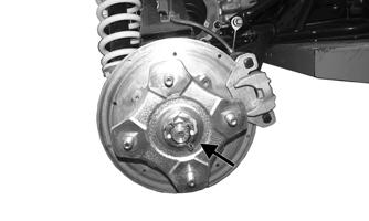
3. Remove the front wheels. 4. Pump up the hand brake; then engage the brake lever lock. 5. Remove and discard the cotter pins securing the hex nuts; then remove the hex nuts.
4. Loosen the front cap screw; then tighten the cap screw on the driveshaft side.
XR099
6. Release the brake lever lock. XR165A
NOTE: It is important to tighten this cap screw
while the others are loose to ensure proper seating of the actuator.
NOTE: It is not necessary to remove the brake hoses from the calipers for this procedure.
111