Engine NOTE: Whenever a part is worn excessively, cracked, or damaged in any way, replacement is necessary.
Engine Removing/ Installing - 6000 This engine sub-section has been organized to show a progression for the removing/installing of the Arctic Cat 6000 engine. For consistency purposes, this sub-section shows a complete and thorough progression; however, for efficiency it may be preferable to remove only those components needing to be addressed. Also, some components may vary from model to model. The technician should use discretion and sound judgment.
SPECIAL TOOLS A number of special tools must be available to the technician when performing service procedures in this engine section. Description
p/n
Drive Clutch Bolt Tool
0644-281
Drive Clutch Puller
0744-062
Drive Clutch Spanner Wrench
0644-136
Hood Harness Extension
1686-659
NOTE: Special tools are available from the Arctic Cat Service Parts Department.
CAUTION Never attempt to substitute any other drive clutch puller for the recommended puller or severe clutch or crankshaft damage will occur.
0746-793A
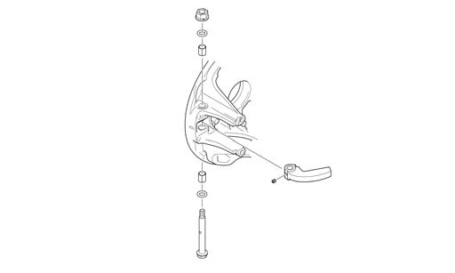
1. Carefully remove the exhaust temperature sensor from the expansion chamber. 2. Remove all springs securing the expansion chamber and resonator; then remove the expansion chamber and resonator. 3. Remove the torx screw from the driven clutch and slide the driven clutch (along with the drive belt) off the driven shaft. Account for alignment washers. 4. Using Drive Clutch Bolt Tool, remove the torx-head screw and high-collar washer securing the drive clutch to the crankshaft. 5. Using Drive Clutch Puller and Drive Clutch Spanner Wrench, tighten the puller. Remove the drive clutch. NOTE: If the drive clutch will not release, sharply strike the head of the puller. Repeat this step until the clutch releases.
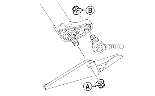
6. Remove the two screws (A) securing the heat shield to the chassis; then remove the heat shield from the two front locating pins (B) and remove the heat shield.
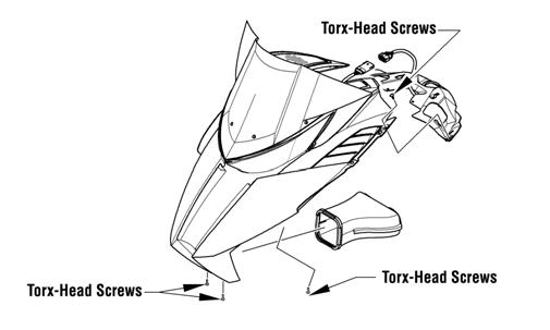
Removing NOTE: For assembling purposes, note cable tie locations securing the harness and cables to the chassis. NOTE: Prior to removing the engine, disconnect the hood harness and remove the side access panels; then remove the screws securing the hood to the chassis. EL-001A
7. Disconnect the ECM; then remove the screws securing the right- and left-side fascia panels to the chassis. Remove the panels and ECM as an assembly.
28