25 minute read
Engine-Related Items

NOTE: Whenever a part is worn excessively, cracked, or damaged in any way, replacement is necessary.
SPECIAL TOOLS A number of special tools must be available to the technician when servicing the engine-related items.
Description p/n
Blind-Hole Bearing Puller Coolant Cap 0644-500 0644-156
Drive Clutch Spanner Wrench 0644-136
Valve and Spring Retainer Tool
0644-448 Fan Spanner Wrench 0644-340 Water Pump Bearing and Seal Tool Kit 0644-557 Oil Seal Protector Tool 0644-219 Engine Leak-Down Test Kit 0644-522 Vacuum Test Pump 0644-131 Hood Harness Extension 1686-659 Hood Harness Extension 1686-660 Oil Filter Wrench 0644-551
NOTE: Special tools are available from the Arctic Cat Service Parts Department.
Water Pump (8000)
DISASSEMBLING
NOTE: The engine must be removed for this procedure.
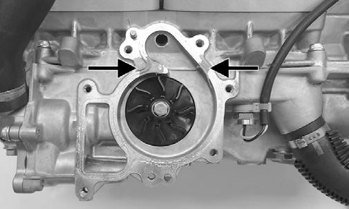
NOTE: A bleed hole is located in the crankcase beneath the water pump housing. If any signs of coolant leakage from the bleed hole exist, the water pump seals must be replaced.
FS219A
NOTE: When servicing the water pump, use Water Pump Bearing and Seal Tool Kit and Oil Seal Protector Tool.
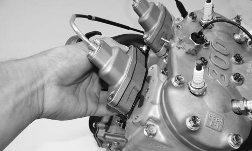
1. Loosen the clamps securing the coolant hoses to the water pump; then remove the hoses.
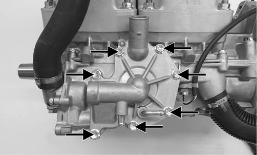
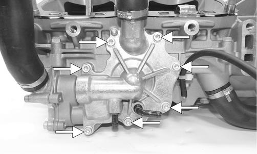
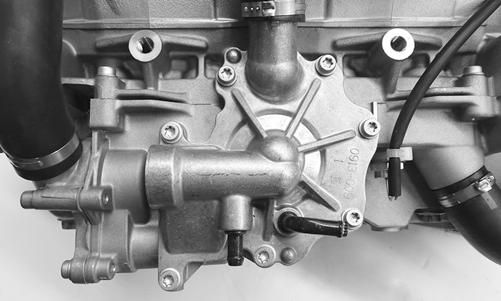
XM114A 2. Remove the seven cap screws securing the water pump cover; then remove the cover and account for the O-ring seal and two dowel pins.
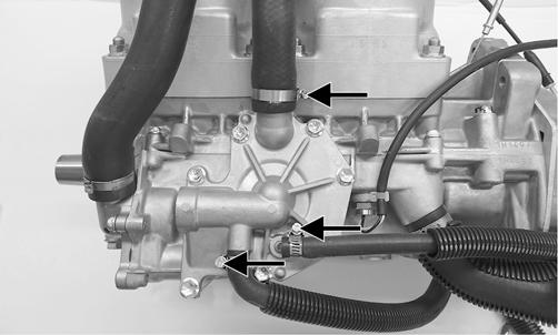
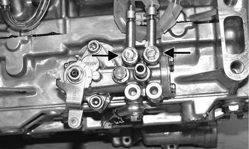
XM113A 3. Remove the cap screw (A) securing the lower check valve to the oil pump and account for the two gaskets; then remove the two cap screws (B) securing the oil pump to the engine. Remove the pump.
FS220A
NOTE: Leave the two upper check valves secured to the pump.
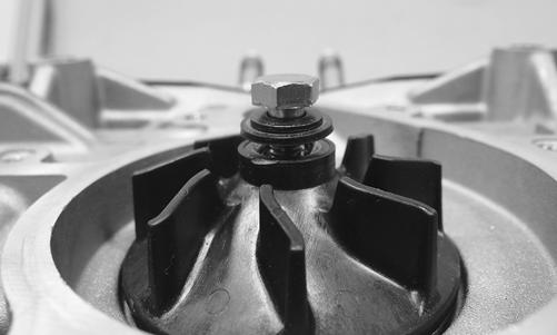
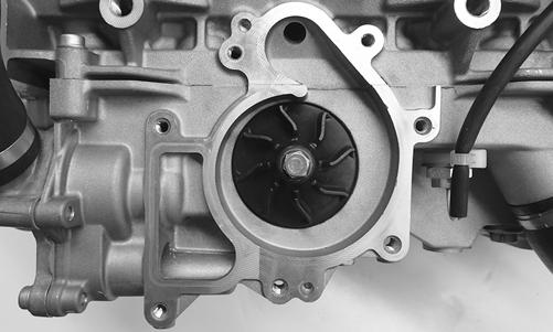
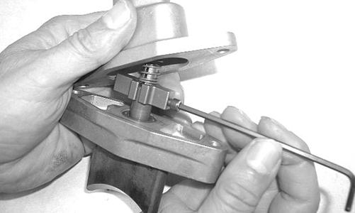
FS221A 4. Remove the cap screw securing the impeller. Account for the rubber washer and gasket behind the cap screw.

XM112
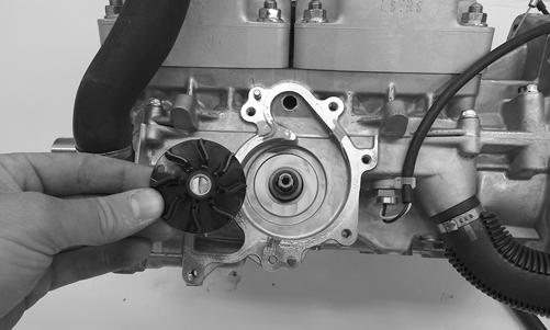
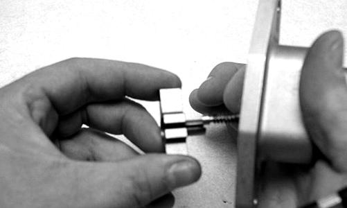
5. Remove the impeller from the shaft.
XM111
NOTE: If the impeller will not slide off the shaft, start the cap screw into the shaft and tap on the cap screw driving the shaft back out of the impeller.
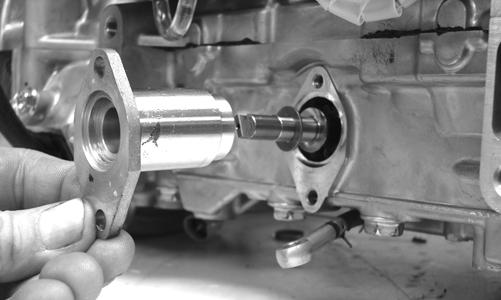
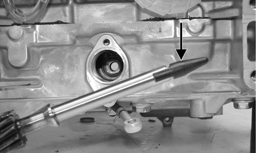
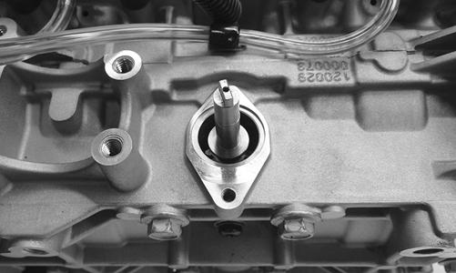
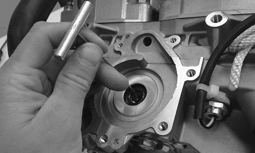
6. Remove the oil-injection pump retainer and shaft from the opposite side of the crankcase. Account for the shim located between the retainer and shaft flange.
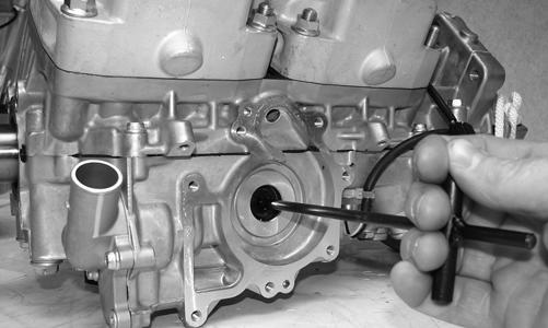
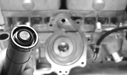
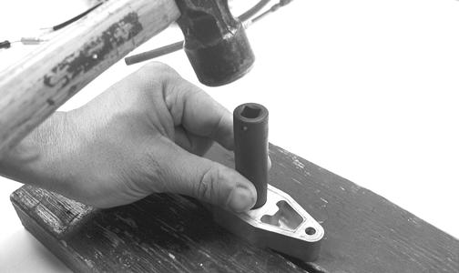
FS226 7. Using the long seal driver, drive the water pump mechanical seal from the crankcase.
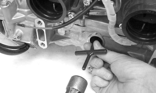
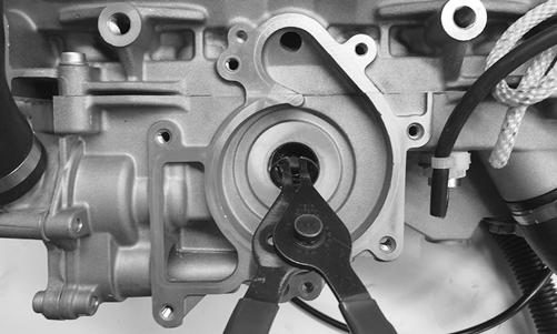
FS227 8. Using a pair of snap ring pliers, remove the snap ring securing the oil seal in the crankcase.
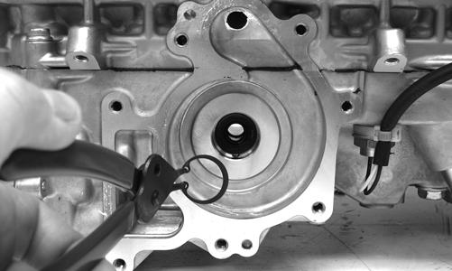
FS228 9. Using the hooked end of the long seal driver, pull the inner seal free of the crankcase.
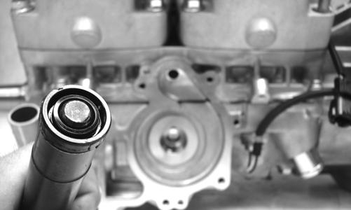
ASSEMBLING 1. Thoroughly clean the seal surfaces of the crankcase. 2. Position the oil seal onto the seal driver (spring side towards the crankshaft). Gently tap into position.
FS230 3. Apply a small amount of grease to the oil seal lips. 4. Using a pair of snap ring pliers, install the snap ring securing the oil seal in the crankcase.
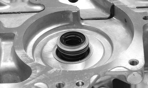
FS228 5. Using the seal driver, carefully install the outer water pump mechanical seal. Gently tap the seal down into position until it seats itself against the crankcase.
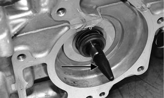
FS232 6. Apply a light coat of grease to the sealing surface of the oil-injection pump driveshaft; then install Oil
Seal Protector Tool at the end of the shaft. Twist the shaft while pushing it through the oil and water pump seals until the shaft gear engages with the drive gear of the crankshaft; then remove the tool.
FS233A
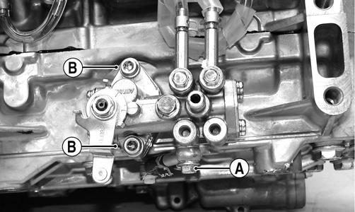
IO025B 7. Position the shim (A) on the oil pump end of the shaft; then with the O-ring in place on the retainer (B), install the oil-injection pump retainer.
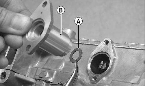
IO026A 8. With the O-ring in place on the oil-injection pump, align the pump with the shaft; then install the pump.
Secure with the cap screws (coated with blue Loctite #243) (B) and tighten to 96 in.-lb. Place the lower check valve into position; then secure with the gaskets and cap screw (A). Tighten to 48 in.-lb.
FS220A
NOTE: When installing the lower check valve, assure that the gaskets are installed on each side of the valve.
FS235A
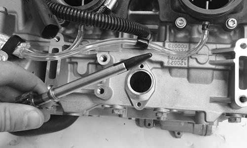
NOTE: After the oil pump has been secured, assure that the oil hoses from the pump to the intake flanges are routed properly.
9. Place the impeller into position and secure with a cap screw and washer. Be sure the rubber side of the washer is directed towards the impeller. Apply blue
Loctite #243 to the threads of the cap screw and tighten to 48 in.-lb.
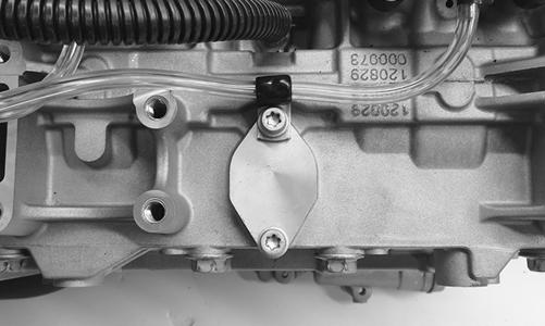
XM112 10. Apply sealant to the crankcase seam; then install the alignment pins into the crankcase (if removed).
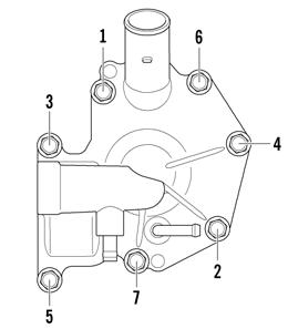
XM112A 11. Position the O-ring into the water pump cover; then install the cover. Install the cap screws; then using the pattern shown, tighten to 96 in.-lb.
12. Secure the hoses to the water pump cover.
0742-257
Water Pump (6000)
DISASSEMBLING
NOTE: The engine must be removed for this procedure.
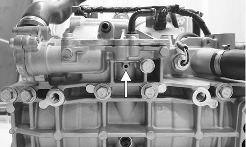
NOTE: A bleed hole is located in the crankcase beneath the water pump housing. If any signs of coolant or oil leakage from the bleed hole exist, the seals must be replaced.
CWI-094A
NOTE: When servicing the water pump, use Water Pump Bearing and Seal Tool Kit and Oil Seal Protector Tool.
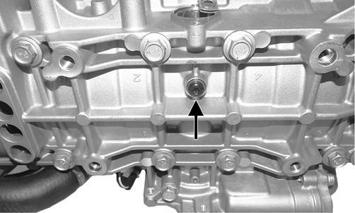
NOTE: Tip the crankcase assembly up onto the water pump side; then remove the black torx-screw from the bottom of the crankcase and tip down and drain the injection oil from the center cavity into a container.
CWI-023A 1. Loosen the clamps securing the coolant hoses to the water pump; then remove the hoses. 2. Remove the seven screws securing the water pump cover; then remove the cover and account for the Oring seal and two dowel pins.
CWI-016A 3. Remove the cap screw securing the impeller. Account for the rubber washer and gasket behind the cap screw.
Remove the impeller from the shaft.
CWI-082 NOTE: If the impeller will not slide off the shaft, start the cap screw into the shaft and tap on the cap screw driving the shaft back out of the impeller.
4. Remove the retainer and shaft from the opposite side of the crankcase. Account for the shim located between the retainer and shaft flange.
CWI-097 5. Using the long seal driver, drive the water pump mechanical seal from the crankcase. 6. Using a pair of snap ring pliers, remove the snap ring securing the oil seal in the crankcase.
CWI-098 9. Using the hooked end of the long seal driver, pull the inner seal free of the crankcase.
CWI-099
ASSEMBLING 1. Thoroughly clean the seal surfaces of the crankcase. 2. Position new oil seal onto the seal driver (spring side towards the crankshaft). Gently tap into position.
FS230 3. Apply a small amount of grease to the oil seal lips. 4. Using a pair of snap ring pliers, install the snap ring securing the oil seal in the crankcase.
CWI-098 5. Using the seal driver, carefully install the outer water pump mechanical seal. Gently tap the seal down into position until it seats itself against the crankcase.
FS232 6. Apply a light coat of grease to the sealing surface of the pump driveshaft; then install Oil Seal Protector
Tool at the end of the shaft. Twist the shaft while pushing it through the water pump seals until the shaft gear engages with the drive gear of the crankshaft; then remove the tool.
CWI-101 7. Position the shim on the retainer end of the shaft; then with the O-ring in place on the retainer, install the retainer.
CWI-100 9. Place the impeller into position and secure with a cap screw and washer. Be sure the rubber side of the washer is directed towards the impeller. Apply blue
Loctite #243 to the threads of the cap screw and tighten to 48 in.-lb.
CWI-096 11. Position the O-ring into the water pump cover; then install the cover. Install the cap screws; then tighten to 96 in.-lb using a crisscross pattern.
CWI-095
12. Secure the hoses to the water pump cover.
Pressure Testing Engine
NOTE: To pressure test the engine, use Engine Leak-Down Test Kit.
Liquid Cooling System
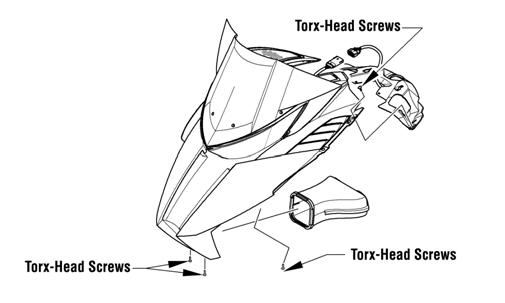
The liquid cooling system consists of heat exchangers, water pump, coolant temperature sensor, and thermostat. The system should be inspected for leaks or damage whenever an overheating problem is experienced. DRAINING COOLING SYSTEM 1. Remove the access panels; then disconnect the hood harness and remove all screws securing the hood.
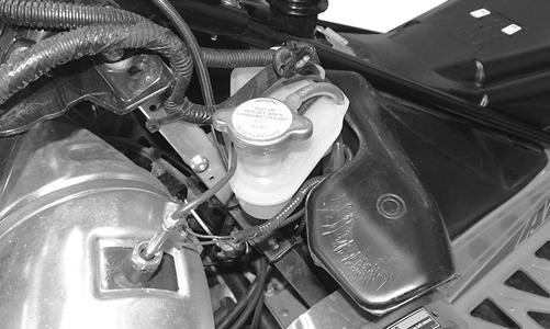
Remove the hood. 2. With the engine cool, remove the coolant cap; then using a suitable coolant vacuum pump, remove as much coolant as possible from the coolant tank.
XM213 3. Remove all springs securing the expansion chamber; then with the expansion chamber removed, loosen the clamp securing the lower coolant hose behind the engine. Remove as much coolant as possible using the coolant vacuum pump.
XM209A
NOTE: Raising the rear end of the snowmobile will aid in removing all coolant from the heat exchangers.
4. Once the coolant has completely drained, secure the lower coolant hose using the existing clamp. FILLING COOLING SYSTEM 1. Elevate the front of the snowmobile 30-35 cm (12-14 in.). 2. Remove the coolant tank cap and check coolant level. The coolant tank should be filled to the coolant level line. 3. Install the coolant tank cap; then start the engine.
Run the engine at 3000-3500 RPM until the bottom heat exchangers become hot to the touch. Stop the engine and allow the system to cool. 4. Lower the front of the snowmobile and elevate the rear of the snowmobile 12-14 in. Repeat the procedures in step 3. 5. Check the coolant level. Add coolant as required to the coolant tank (coolant tank should be filled to coolant level line). Repeat procedure until coolant level stabilizes in the coolant tank.
CAUTION
The cooling system must be properly filled. If the system isn’t properly filled, piston damage will occur.
NOTE: If coolant is required, mix coolant for a temperature of -36°C (-34°F). Follow mixing recommendations of the manufacturer of the coolant.
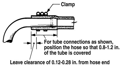
INSPECTING COOLANT HOSES AND CLAMPS All coolant hoses and connections should be checked annually for deterioration, cracks, and wear. All coolant hoses and clamps should be replaced every four years. INSPECTING THERMOSTAT 1. Inspect the thermostat for corrosion, wear, or spring damage. 2. Using the following procedure, inspect the thermostat for proper operation.
a. Suspend the thermostat in a container filled with water; then heat the water and monitor the temperature with a thermometer. b. The thermostat should open at 30°C (86°F). Once the thermostat starts to open, remove the thermostat and allow it to cool down verifying it has returned to the fully closed position.
Cooling System Schematic
The following schematic is representative of the different styles of cooling systems in the Arctic Cat snowmobiles. Some components may vary from model to model; therefore, the technician should use discretion and sound judgment when servicing a particular cooling system. CAUTION
Never heat the thermostat to the fully open position or damage to the thermostat may occur.
Recoil Starter
KEY
A. Cap Screw
B. Roller
C. Friction Plate
D. Cap Screw w/Washer
E. Pawl Activator
F. Pawl
G. Return Spring
H. Friction Plate Spring
I. Main Spring 0747-869

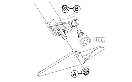
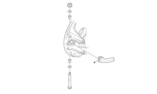
REMOVING 1. Tie a slip-knot in the starter rope below the console and allow the rope to slowly retract against the starter case. 2. Remove the knot at the handle, remove the handle, and account for the handle cap; then thread the rope through the bushing in the console. 3. Remove the cap screws (A) securing the starter assembly to the magneto case; then remove the starter assembly.
741-373B
Always wear safety glasses and gloves when servicing the recoil starter. 1. Secure the recoil starter in a vise.
2. Rotate the roller (B) counterclockwise until the notch of the roller is near the rope guide in the case. Guide the rope into the notch and slowly allow the roller to retract until all recoil spring tension is released.
3. While exerting downward pressure on the friction plate (C), remove the cap screw with washer (D). 4. Slowly release the friction plate and lift the plate with pawl activator (E) free of the recoil roller; then remove the pawl activator from the friction plate. 5. Remove the pawl (F) and the return spring (G); then remove the friction plate spring (H). 6. Carefully lift the roller free of the case making sure the main spring (I) does not disengage from the case.
Account for the bushing.
7. Remove the main spring from the case by lifting the spring end up and out. Hold the remainder of the spring with thumbs and alternately release each thumb to allow the spring to gradually release from the case. ! WARNING
During the disassembly procedure, continuous downward pressure must be exerted on the reel so it does not accidentally disengage and cause injury.
! WARNING
Care must be taken when allowing the recoil roller to unwind. Make sure all spring tension is released before continuing.
! WARNING
Care must be taken when lifting the roller free of the case.
NOTE: Do not remove the main spring unless replacement is necessary. It should be visually inspected in place to save time.
8. Unwind the rope from the roller, untie the slip-knot, and remove the rope. CLEANING AND INSPECTING 1. Clean all recoil starter components. 2. Inspect springs and pawl for wear or damage. 3. Inspect the roller and case for cracks or damage. 4. Inspect the center hub for wear, cracks, or damage. 5. Inspect the rope for breaks or fraying. 6. Inspect the main spring for cracks, crystallization, or abnormal bends. 7. Inspect the handle for damage, cracks, or deterioration. ASSEMBLING 1. Hook the end of the main spring around the mounting lug in the case. 2. Insert the main spring into the case; then wind it in a counterclockwise direction until the complete spring is installed.
NOTE: The main spring must seat evenly in the recoil case.
3. Insert the rope through the hole in the roller and tie a knot in the end; then wrap the rope counterclockwise around the roller leaving approximately 20 in. of rope free of the roller. 4. Apply low-temperature grease to the main spring and hub. 5. Align the hook in the end of the main spring with the notch in the roller. 6. Carefully slide the roller over the hub and engage the spring with the roller; then install the bushing. 7. Install the return spring making sure the short leg of the spring is properly installed in the hole in the roller; then install the pawl making sure the return spring is properly positioned in the notch of the pawl. 8. Slide the end of the rope through the rope guide of the case; then tie a slip-knot in the rope. 9. Apply a low-temperature grease to the friction plate.
Place the pawl activator into position on the friction plate making sure the arms of the activator are properly positioned to the pawl. 10. Place the friction plate into position allowing it to rest on the friction plate spring; then install the cap screw w/washer (coated with blue Loctite #243) and thread the cap screw in until it contacts the friction plate. 11. Press down on the friction plate and tighten the cap screw to 15 ft-lb. 12. With 20 in. of rope exposed, hook the rope in the notch of the roller. 13. Rotate the roller four or five turns counter-clockwise; then release the rope from the notch and allow the rope to retract. 14. Pull the rope out two or three times to check for correct tension.
NOTE: Increasing the rotations in step 13 will increase spring tension.
INSTALLING 1. Place the starter assembly into position against the magneto case. 2. Secure the starter with cap screws. Tighten to 96 in.lb.
NOTE: Before tightening the cap screws, slowly pull the recoil rope until the pawl engages; then tighten the cap screws centering the recoil against the magneto case.
3. Thread the rope through the bushing in the console; then install the handle and secure with a knot. Seat the cap. 4. Release the slip-knot in the rope.
Arctic Power Valve (APV) System
The Arctic Power Valve (APV) System adjusts the size of the exhaust ports to produce maximum horsepower on the top end while providing excellent low end power and increased touring fuel economy. THEORY Two-cycle engines and their exhaust systems are designed to produce maximum horsepower in a given RPM range. This RPM range will change according to how high (or low) the exhaust port is in relation to the cylinder. Engines designed for racing have a “high port” exhaust system and will produce more horsepower at higher RPM but only with the loss of low end power and overall fuel economy. “Low port” engines will produce maximum horsepower in the low RPM ranges and provide good mid-range fuel economy, but they sacrifice top end performance. The APV system does not increase engine horsepower, but it does allow the engine to be designed for maximum top end horsepower without the losses associated with a “high port” exhaust system. COMPONENTS The main components of the APV system are the following.
A.Lighting Coil
B.Voltage Regulator/Rectifier
C.ECM
D.Servomotor
E.Power Valve Cables
F. Power Valves Lighting Coil The AC current generated by the lighting coil flowing to the regulator/rectifier is the power source for the APV system. Voltage Regulator/Rectifier The AC current from the power coil first enters the regulator/ rectifier changing from AC current to DC current. Since the APV circuit cannot use pulsating DC current, it must be converted (by the condenser) to straight DC current. AC current enters the ECM from the lighting coil and is changed from AC to DC current by a rectifier located within the ECM. ECM The computer within the ECM has been programmed to cycle the power valves at 4500 RPM upon initial start-up. When this RPM is reached, DC current is routed to the servomotor by the ECM. Servomotor The servomotor consists of two circuits. One circuit is a DC circuit operating the DC motor within the servomotor, and the other is a potentiometer measuring the pulley position based on voltage. The computer within the ECM has been programmed to operate the servomotor between a low and high voltage range. If voltage is not within the range, the computer will shut down the APV circuit. The computer will then make a total of three more attempts to cycle the power valves. If the correct voltage or pulley position isn’t seen, the APV circuit is shut down and no more attempts will be made until the engine is shut down and restarted. Exhaust Valve Cables The exhaust valves are connected to the actuating cables and, along with the return springs, are contained inside the APV housing on the exhaust side of each cylinder. The other end of the actuating cable is connected to the servomotor. OPERATION At idle and low speed operation, the exhaust valves are held in the “low port” position by the return spring. When engine RPM reaches a predetermined point, the ECM will send a signal to the servomotor which cycles and pulls the exhaust valves into the mid-point. At another RPM, the ECM will send a signal to the servomotor which cycles and pulls the exhaust valves to the up or “high port” position. If the servomotor cycles the exhaust valves as explained above, the exhaust valve circuit is operating satisfactorily. If the servomotor makes no attempt to open the valves or if the servomotor attempts to cycle the valves three times (then stops working), a problem exists and it must be corrected. Servomotor Cycles Three Times In this situation the ECM computer has been programmed with a voltage range (low and high) that the servomotor must operate within. If the servomotor is put under too much load, its resistance goes up and may exceed the range upper limit. It will then stop and attempt two more times. If the resistance still is too high, it shuts down. If the servomotor is commanded to move but the potentiometer output voltage does not change, an error occurs and the check engine light will flash a trouble code. Improper servomotor position sensing is normally caused by one or more of the following:
A.Incorrect exhaust valve cable length (too long or too short).
B.Exhaust valve cable(s) sticking, broken, or disconnected at pulley.
C.Exhaust valves sticking.
D.Exhaust valve spring(s) weak or broken.
Check each of the above probable causes in the order given to locate the problem of the servomotor cycling three times in succession; then shutting down. Check for correct exhaust valve cable length specifications for model being worked on in this section. Servomotor Makes No Attempt To Cycle If when running the engine the servomotor makes no attempt to operate, this is caused by one or more of the following:
A.Bad connection from the wiring harness and connector from the lighting coil to the ECM, or from the ECM to servomotor.
B.ECM output to servomotor is too low.
C.Servomotor failure.
D.Blown fuse.
E.Voltage Regulator/Rectifier. NOTE: For testing individual APV system components, see the Electrical Systems section.
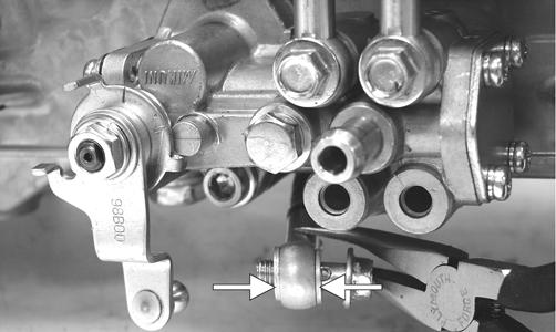
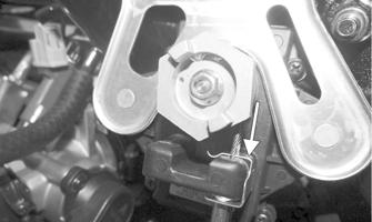
MAINTENANCE The APV system requires only periodic cleaning and cable adjustment. The cables should be checked every 2600 miles and adjusted as necessary. CABLE ADJUSTMENT Proper cable adjustment is critical to the operation of the APV system. To check the cable adjustment, use the following procedure. 1. Using a small needle-nose pliers, remove the servomotor cable holder.
PC187A 2. Pull the cable housings down and out of the servomotor; then slide each cable end out of the slot of the pulley.
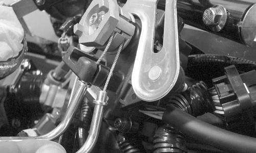
PC134
NOTE: Ensure the exhaust valves are free to move.
3. While holding the cable housing firmly, pull the cable as far out as it will go; then release. Repeat three to four times. The cable/exhaust valve should move freely without binding. If the cable/exhaust valve does not move freely, the exhaust valve assembly will need to be removed for further inspection. NOTE: When measuring the cables, they are to be routed and as close to their installed position as possible.
4. While holding the cable housing, lightly pull on one cable end to remove any slack; then measure the amount of exposed cable from the cable housing to the end of the cable.
NOTE: The two cable measurements must be equal in length or less than 0.5 mm (0.020 in.) difference in length from each other.
NOTE: Repeat steps 3 and 4 for each cable; then compare the measurements to the APV Cable Length chart in the General Information section. The measurements must be within the specifications from the chart. If the measurements are within specifications, no adjustment is necessary (proceed to step 7). If they are not within specifications, proceed to step 5.
5. Loosen the jam nut on the cable to be adjusted; then using the adjusting nuts, lengthen or shorten the housing as needed. 6. Once the proper length has been attained, hold the adjusting nut in place and tighten the jam nut securely. 7. Insert the servomotor cable ends into the slot in the pulley. Secure the cables with the holder. NOTE: If the pulley was removed from the servomotor, align the space between the two cable slots with the mark on the shaft of the servomotor. Tighten the nut to 35 in.-lb.
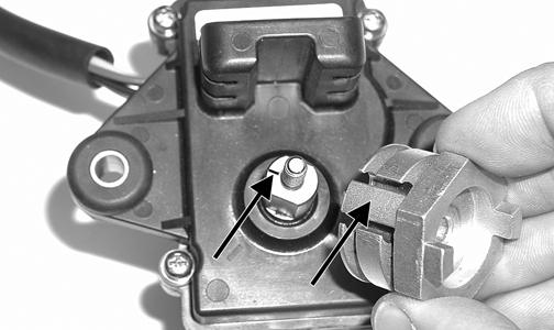
MS401A
CAUTION
Never attempt to remove or install the pulley jam nut with the pulley unsecured or damage to the servomotor will occur.
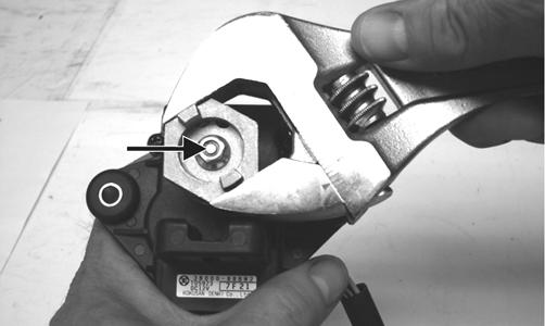
FZ087A
REMOVING/DISASSEMBLING NOTE: To avoid a parts mix-up, only remove one valve assembly at a time from the engine.
1. Remove the exhaust valve assembly from the engine.
XM017 2. Remove the retaining screw securing the exhaust valve to the valve stopper.
FC112 3. Hold the valve stopper securely and pull the cable back and up until it clears the top of the stopper; then slowly release the cable and remove it from the valve stopper.
FC113
Cleaning and Inspecting 1. Remove all carbon deposits with solvent and a soft abrasive such as a Scotch-Brite pad. 2. Inspect all parts for nicks, burrs, or other signs of unusual wear. Replacing Oil Seal 1. Carefully pry the seal up from beneath taking care not to damage the valve plate. 2. Install the new seal using an appropriate-sized seal driving tool.
FC117

KEY
A. Exhaust Valve
B. Cover Gasket
C. Valve Plate D. Oil Seal E. Gasket F. Stopper G. Stopper Pin H. Return Spring I. Valve Cover
FC111A 1. Slide the return spring over the end of the actuating cable.
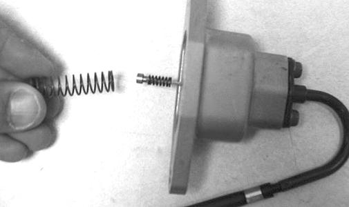
FC114
NOTE: Make sure that the small cable end spring stays in place at the end of the cable.
2. With the cover gasket properly positioned, place the valve stopper on the cable end and slide it down until the cable end is inside the stopper.
FC113 3. With the valve plate gasket properly positioned, slide the exhaust valve through the valve plate and insert it into the valve stopper. Secure with the retaining screw. Tighten to 48 in.-lb.
FC112
NOTE: Note that the exhaust valve gaskets are directional and must be installed correctly.
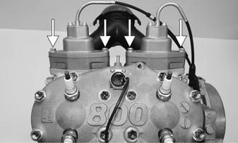
4. Slide the exhaust valve assembly into the cylinder.
XM017 5. Place the valve cover into position on the engine.
Secure with two cap screws. Tighten to 96 in.-lb.
XM024A 6. Perform steps 5-8 in Cable Adjustment in this subsection. TROUBLESHOOTING The APV system has a self-testing mode built in. Every time that the engine is started, the servomotor will cycle once. The ECM monitors the voltages at the servomotor during this cycle to assure they are within operational tolerances. If all voltages are within tolerance, the system is ready for operation. If the voltages are not within tolerance, the servomotor will cycle two more times. If the voltages remain out of tolerance, the system will not operate.
For example, if the headlight and taillight are disabled, the ECM will sense a high voltage condition and activate the fail-safe mode. Adding more than 4 amps of accessories will create a low voltage condition and activate the fail-safe mode. The fail-safe mode is an ECM operated engine RPM limiter. When activated, the fail-safe mode will be seen as an immediate loss of engine horsepower.
Problem: Engine loses power; no top end Condition Remedy 1. Exhaust valves sticking in 1.Remove carbon deposits, down position burrs, etc. 2.Cables adjusted too long 2. Inspect—adjust 3. Regulator/Rectifier output 3.Inspect—replace Regulavoltage out of tolerance tor/Rectifier/stator Problem: Poor acceleration; hesitation Condition Remedy 1.Exhaust valve sticking in 1.Remove carbon deposits, up position burrs, etc.—inspect/ replace return spring 2.Cables adjusted too short 2.Inspect—adjust 3. Regulator/Rectifier output 3.Inspect—replace voltage out of tolerance Regulator/Rectifier/ stator
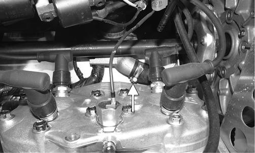
Exhaust Controlled Timing (ECT) System
These models are equipped with the Exhaust Controlled Timing (ECT) system utilizing an exhaust pipe temperature sensor.
NOTE: The engine has a three-stage exhaust valve system. The stages are closed, mid-open, and fullopen. These models have a designated RPM of 4500 at which the system is synchronized and checked by the ECM for proper operation occurring once each time the engine is started.
This system automatically adjusts the ignition timing to provide maximum performance through a variety of operating conditions. The ECM receives input on engine RPM (demand) and exhaust temperature (engine condition) and adjusts the ignition timing accordingly. This system is not adjustable and is maintenance free. If a system fault is suspected, use an ohmmeter to check continuity of the exhaust pipe temperature sensor located in the expansion chamber. A reading of either 0 ohm or infinity indicates a failed sensor. NOTE: A disabled ECT system WILL NOT cause engine damage; however, a failed ECT system will have slower throttle response and may produce slightly less top-end performance.