79 minute read
Engine

NOTE: Whenever a part is worn excessively, cracked, or damaged in any way, replacement is necessary.
Engine Removing/ Installing - 6000
This engine sub-section has been organized to show a progression for the removing/installing of the Arctic Cat 6000 engine. For consistency purposes, this sub-section shows a complete and thorough progression; however, for efficiency it may be preferable to remove only those components needing to be addressed. Also, some components may vary from model to model. The technician should use discretion and sound judgment. SPECIAL TOOLS A number of special tools must be available to the technician when performing service procedures in this engine section.
Description
Drive Clutch Bolt Tool Drive Clutch Puller Drive Clutch Spanner Wrench Hood Harness Extension p/n
0644-281 0744-062 0644-136 1686-659 NOTE: Special tools are available from the Arctic Cat Service Parts Department.
CAUTION
Never attempt to substitute any other drive clutch puller for the recommended puller or severe clutch or crankshaft damage will occur.
Removing
NOTE: For assembling purposes, note cable tie locations securing the harness and cables to the chassis.
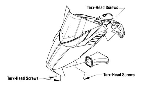
NOTE: Prior to removing the engine, disconnect the hood harness and remove the side access panels; then remove the screws securing the hood to the chassis.
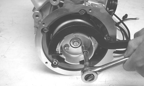
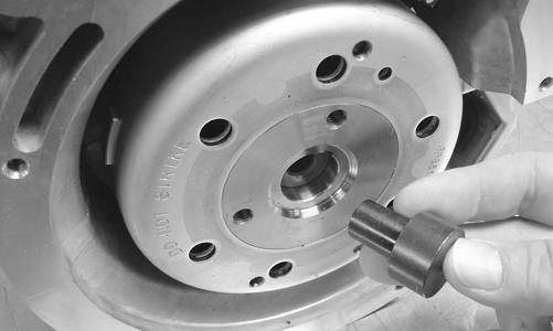
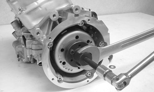
0746-793A 1. Carefully remove the exhaust temperature sensor from the expansion chamber. 2. Remove all springs securing the expansion chamber and resonator; then remove the expansion chamber and resonator. 3. Remove the torx screw from the driven clutch and slide the driven clutch (along with the drive belt) off the driven shaft. Account for alignment washers. 4. Using Drive Clutch Bolt Tool, remove the torx-head screw and high-collar washer securing the drive clutch to the crankshaft. 5. Using Drive Clutch Puller and Drive Clutch Spanner
Wrench, tighten the puller. Remove the drive clutch. NOTE: If the drive clutch will not release, sharply strike the head of the puller. Repeat this step until the clutch releases.
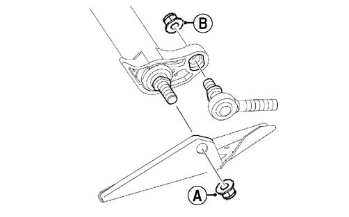
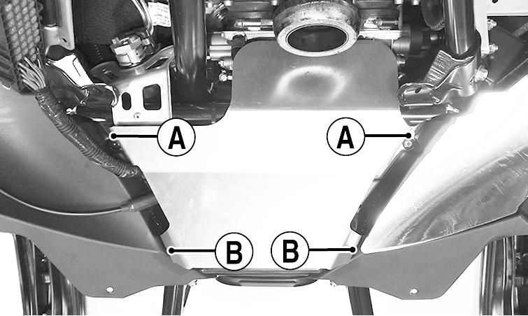
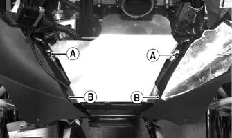
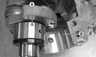
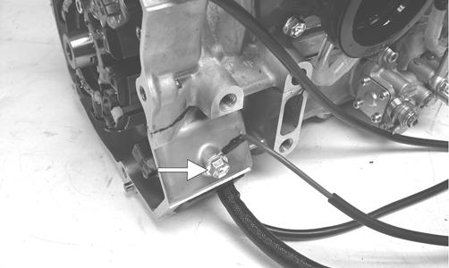
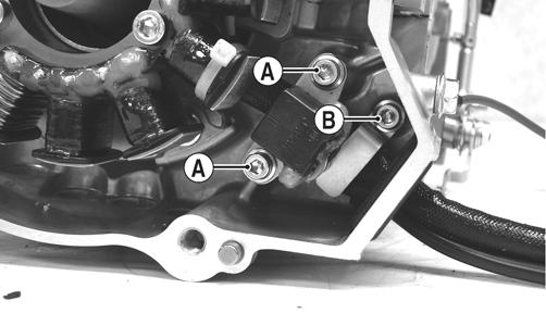
6. Remove the two screws (A) securing the heat shield to the chassis; then remove the heat shield from the two front locating pins (B) and remove the heat shield.
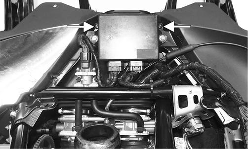
EL-001A 7. Disconnect the ECM; then remove the screws securing the right- and left-side fascia panels to the chassis. Remove the panels and ECM as an assembly.
EL-002A 8. Remove the cap screws securing the PTO-side front spar to the steering support and shock mount bracket; then remove the spar. NOTE: Take care to not drop the spar inserts and nuts when removing the spar.
9. Using a small needle-nose pliers, remove the servomotor cable holder; then pull the cable housings down and out of the servomotor.
EL-004A 10. Slide each cable end out of the slot of the clutch; then disconnect the harness from the servomotor. 11. Remove the cap screws and lock nuts securing the shock mount bracket support to the shock mount brackets; then remove the shock mount bracket support.

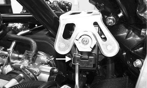
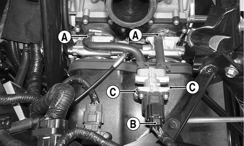
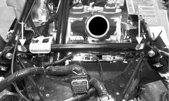
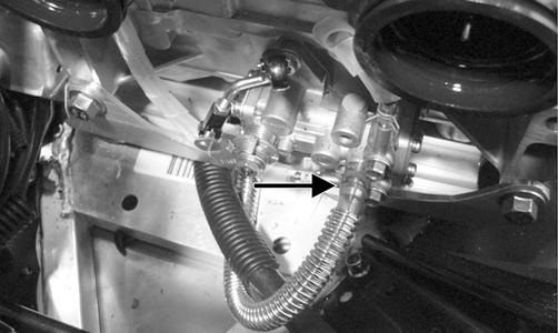
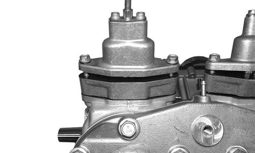
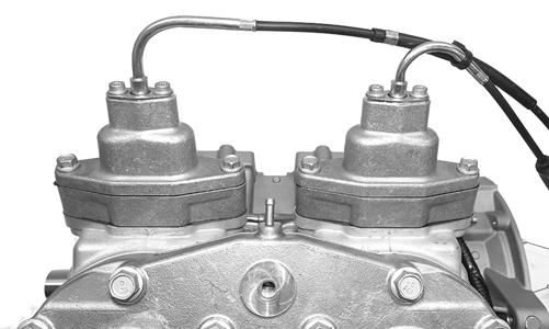
EL-003A 12. Remove idle speed control (ISC) hoses (A) from the top of the throttle bodies; then disconnect the ISC from the main harness (B). Remove the screws (C) securing the ISC; then remove the ISC.
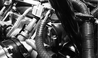
EL-006A 13. Loosen the four clamps securing the throttle body; then lift up the throttle body and disconnect the coolant hoses. Set the throttle body up and out of the way. 14. Remove the intake boot from the chassis. 15. Remove all three oil hoses from the front of the engine.

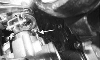
EL-005A 16. Loosen the clamp securing the gasline hose to the throttle body and remove the hose; then close-off the hose and secure the hose up and out of the way.
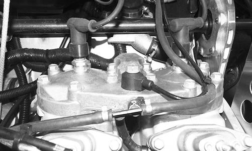
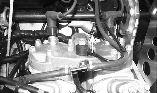
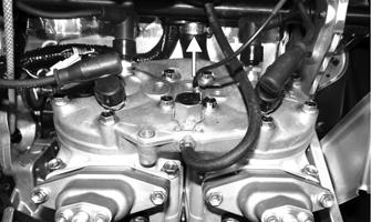
17. Remove the main harness wrap and disconnect the six harness connectors. Secure the harness up and out of the way. 18. Remove the recoil starter from the engine. Secure it out of the way. 19. Remove the cap screws securing the MAG-side engine mount to the engine. 20. Remove the spark plug caps from the spark plugs; then disconnect the knock sensor and coolant temperature sensor connectors. Remove the cylinder head vent hose.
! WARNING
The hose may be under pressure; remove it slowly to release the pressure. Place an absorbent towel around the connection to absorb gas.
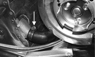
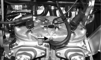
CWI-092 21. Disconnect the lower coolant hose from the front heat exchanger; then remove the coolant hose from the heat exchanger at the rear of the engine.
PC141A
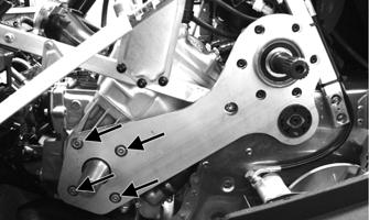
PC178A 22. Remove the four screws securing the PTO-side engine mounting plate to the engine. NOTE: Before removing the cap screws, apply a sufficient amount of heat to the cap screws to soften the Loctite.
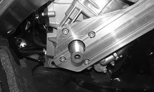
CWI-093 23. Remove the cap screw and two lock nuts securing the engine support plate to the chassis; then lift the engine out of the engine compartment. NOTE: If replacing the engine, make sure to remove the engine support plate, exhaust manifold, and three coolant hoses for installation on the new engine.
Installing
NOTE: If the engine was replaced, make sure to install the existing engine support plate and the exhaust manifold on the new engine. Tighten the exhaust manifold nuts to 12 ft-lb, the M6 engine support plate cap screws to 25 ft-lb, and the M8 engine cap screws to 35 ft-lb. Install the three coolant hoses.
NOTE: On electric start models, install the starter motor to the engine.
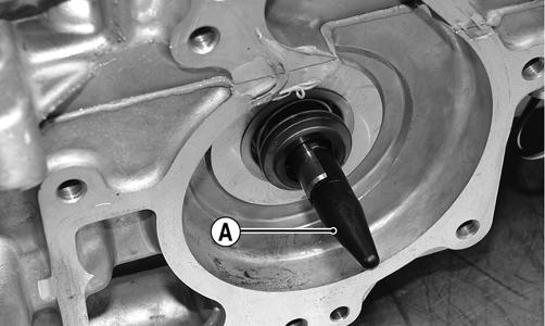
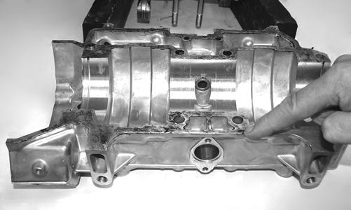
NOTE: If the engine is brand new, tip the crankcase assembly up on the water pump side; then pour Arctic Cat C-Tec2 engine oil into the center cavity of the crankshaft until the oil is level with the shoulder of the shaft (A).

CWI-085A
CAUTION
Failure to fill the center cavity of the crankcase assembly will result in center gear damage and engine failure. 1. Carefully lower the engine into the engine compartment.
2. Install the coolant hose to the heat exchanger at the rear of the engine; then connect the lower coolant hose to the front heat exchanger.
PC141A
PC178A 3. Install new MAG-side engine mount “patch-lock” cap screws. Finger-tighten only at this time. 4. Install a new “patch-lock” cap screw and new lock nuts to secure the engine support plate to the chassis.
Finger-tighten only at this time. 5. Install four new “patch-lock” screws to secure the
PTO-side engine mounting plate. Tighten to 30 ft-lb using a crisscross pattern.
CWI-093 6. Tighten the cap screw and lock nuts (from step 4) to 25 ft-lb. 7. Install the access panel to the center belly panel and chassis and secure using the torx-head screws. Tighten securely. 8. Tighten the cap screws (from step 3) to 25 ft-lb. 9. Connect the knock sensor and coolant temperature sensor connectors; then install the spark plug caps.
Secure the coolant temperature sensor connector with a cable tie. 10. Install the cylinder head vent hose. 11. Place the recoil starter into position and secure with the cap screws. Tighten in a crisscross pattern to 96 in.-lb. 12. Before connecting the wiring harness plug-ins, clean the connectors and apply Dielectric Grease to the seal; then connect all harness connectors making sure all wiring and coolant hoses are routed properly as noted in removing. Install the main harness wrap. NOTE: Use cable ties to secure the wiring harnesses as necessary.
13. Connect all three oil hoses from the front of the engine. Secure using the existing clamps.
EL-005A 14. Connect the MAG-side throttle body coolant hose; then secure with a clamp. 15. Connect the TPS; then lower the throttle body assembly into the engine compartment. 16. Place the throttle body assembly into position and secure with the flange clamps; then connect the gasline hose to the throttle body assembly and tighten the clamp securely.
17. Connect the PTO-side throttle body coolant hose; then secure with a clamp. 18. Fill the cooling system (see Liquid Cooling System in the Engine-Related Items section). 19. Using the existing clamps, secure the intake flanges to the throttle bodies. 20. With the air intake boot properly positioned on the throttle bodies, secure with the existing clamps. 21. Install the shock mount bracket support; then using new lock nuts, secure the support to the shock mount brackets and tighten to 20 ft-lb.
CAUTION
When installing the throttle bodies, make sure the gasline hose is properly routed to avoid premature wear and/or contact with exhaust components.
EL-003A 22. Insert the servomotor cable ends into the slot in the clutch; then connect the servomotor connector.
Secure the cables with the holder.
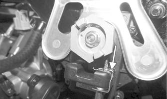
PC187A 23. Rotate the servomotor clockwise to remove any slack from the cables; then install the servomotor retaining clip. Check APV cable adjustment (see
Arctic Power Valve (APV) System in the Engine-
Related Items section). 24. Install the PTO-side front spar and secure to the steering post and shock mount bracket using the existing cap screws. Tighten the cap screws to 25 ft-lb. 25. Secure the idle speed control (ISC) hoses (A) to the top of the throttle bodies using the existing clamps; then connect the ISC to the main harness (B). Secure the ISC to the intake boot using the existing screws (C). Tighten securely.
EL-006A 26. Install the fascia panels (with ECM) and secure to the chassis using the existing screws. Tighten securely. Connect the ECM.
EL-002A
NOTE: At this point, secure the PDM harness to the shock mount bracket support using a cable tie.
27. Position the heat shield onto the two front locating pins (B); then secure it to the chassis with the two screws (A). Tighten securely.
EL-001A 28. Install the resonator and secure with the springs; then place the expansion chamber and gaskets into position and secure to the exhaust manifold and resonator with the springs. NOTE: When installing the manifold springs, the long hook portion of the spring must be attached to the exhaust manifold or premature spring failure will result.
29. Install the exhaust temperature sensor into the expansion chamber. Tighten to 34 ft-lb. 30. Place the drive clutch with drive belt into position on the crankshaft and secure with the cap screw (threads coated with oil) and high-collar washer. Tighten to 51 ft-lb.
CAUTION
When installing the drive clutch, do not tighten the clutch cap screw with any kind of impact tool. Tighten cap screw using a hand torque wrench only. Failure to do so could result in stationary sheave damage.
NOTE: Before installing the drive clutch, be sure to wipe both the crankshaft and clutch mounting tapers clean using a clean towel.
31. Install the driven clutch on the driven shaft; then install the drive belt (see the Drive Train/Track/
Brake Systems section).
32. Check drive belt deflection (see the Drive Train/
Track/Brake Systems section). 33. Place the hood into position on the front end and secure with the screws; then install the hood harness.
Install the side access panels.
34. Start the engine and warm up to operating temperature; then verify that all components are functioning properly and that coolant is circulating through the cooling system properly. 35. After running the engine to the proper operating temperature, shut the engine off; then open the access panels and inspect for any signs of coolant, gasoline, or oil leakage. 36. Allow the engine to cool; then check the coolant level and add coolant as necessary. Verify the tightening torque of the drive clutch.
CAUTION
Never run the engine with the hood harness disconnected or damage to the electrical system will result. CAUTION
If the engine had a major overhaul or if any major component was replaced, proper engine break-in procedures must be followed (see the General Information section) or severe engine damage may result.
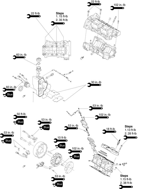
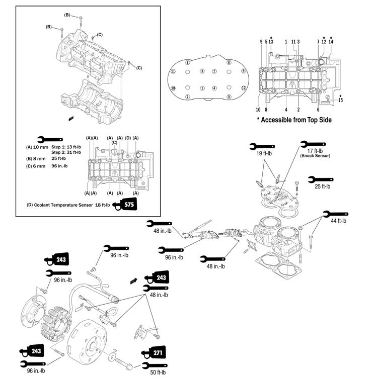
Assembly Schematic - 6000
Torque Specification Tolerances Torque (ft-lb) Tolerance
0-15 ±20%
16-39 40+ ±15% ±10%

600_14_2
Engine Removing/ Installing - 8000
This engine sub-section has been organized to show a progression for the removing/installing of the Arctic Cat 8000 (ZR/M/XF) engine. For consistency purposes, this sub-section shows a complete and thorough progression; however, for efficiency it may be preferable to remove only those components needing to be addressed. Also, some components may vary from model to model. The technician should use discretion and sound judgment. SPECIAL TOOLS A number of special tools must be available to the technician when performing service procedures in this engine section.
Description
Drive Clutch Bolt Tool Drive Clutch Puller Drive Clutch Spanner Wrench Hood Harness Extension p/n
0644-281 0744-062 0644-136 1686-660 NOTE: Special tools are available from the Arctic Cat Service Parts Department.
CAUTION
Never attempt to substitute any other drive clutch puller for the recommended puller or severe clutch or crankshaft damage will occur.
Removing
NOTE: For assembling purposes, note cable tie locations securing the harness and cables to the chassis.
NOTE: Prior to removing the engine, disconnect the hood harness and remove the side access panels; then remove the screws securing the hood to the chassis.
0746-793A 0746-800 1. Remove the rear belt guard; then remove the exhaust temperature sensor from the expansion chamber. 2. Remove all springs securing the expansion chamber and resonator; then remove the expansion chamber and resonator. 3. Remove the cap screw from the driven clutch and slide the driven clutch (along with the drive belt) off the driven shaft. Account for alignment washers. 4. Using Drive Clutch Bolt Tool, remove the torx-head screw and high-collar washer securing the drive clutch to the crankshaft. 5. Using Drive Clutch Puller and Drive Clutch Spanner
Wrench, tighten the puller. Remove the drive clutch. NOTE: If the drive clutch will not release, sharply strike the head of the puller. Repeat this step until the clutch releases.
6. Remove the two screws (A) securing the heat shield to the chassis; then remove the heat shield from the two front locating pins (B) and remove the heat shield.
PC189A 7. Disconnect the ECM; then remove the screws securing the right and left-side fascia panels to the chassis.
Remove the panels and ECM as an assembly.
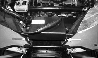
PC188A 8. Remove the caps screws securing the PTO-side front spar to the steering support and shock mount bracket; then remove the spar. NOTE: Take care to not drop the spar inserts and nuts when removing the spar.
9. Using a small needle-nose pliers, remove the servomotor cable holder; then pull the cable housings down and out of the servomotor.
PC187A
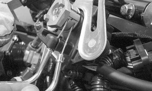
PC134 10. Slide each cable end out of the slot of the clutch; then disconnect the connector from the servomotor. 11. Remove the lock nuts securing the shock mount bracket support to the shock mount brackets; then remove the shock mount bracket support.
PC186A 12. Drain the engine coolant (see Liquid Cooling System - the Engine-Related Items section). 13. Loosen the clamp securing the gasline hose to the throttle body and remove the hose; then close-off the hose and secure the hose up and out of the way.
PC135A
! WARNING
The hose may be under pressure; remove it slowly to release the pressure. Place an absorbent towel around the connection to absorb gas. 14. Loosen the clamps securing the air intake boot to the throttle bodies and pull the air intake boot forward enough to gain access to the throttle body assembly.
Remove and retain the clamps. 15. Loosen the flange clamps securing the throttle body assembly to the intake flanges and disconnect the oilinjection control rod from the throttle body; then loosen the clamps securing the throttle body coolant hoses. Disconnect the TPS and move the throttle body assembly forward and out of the way.
16. Remove the main harness wrap and disconnect the six harness connectors. Secure the harness up and out of the way. 17. Close-off the oil hose with a clamping device; then remove the hose clamp and oil hose from the oil pump.
PC139A 18. Remove the recoil starter from the engine. Secure it out of the way. 19. Remove the cap screws securing the MAG-side engine mount to the engine. Discard the cap screws. 20. Remove the spark plug caps from the spark plugs; then disconnect the knock sensor and coolant temperature sensor connectors. Remove the cylinder head vent hose.
PC178B 21. Disconnect the lower coolant hose from the front heat exchanger; then remove the coolant hose from the heat exchanger at the rear of the engine.
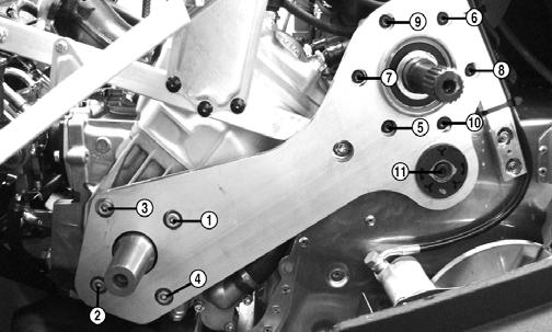
PC141A PC178A 22. Remove and discard the eleven screws securing the
PTO-side engine mounting plate. Account for the spring washer between the rear mount and the tunnel.
NOTE: Before removing the cap screws, apply a sufficient amount of heat to the cap screws to soften the Loctite.
23. Remove the torx-head screw securing the front belt guard to the skid plate; then remove the three cap screws and carriage bolt nut securing the PTO-side chassis support to the shock mount bracket and chassis. Remove the chassis support and account for the carriage bolt. 24. Remove the torx-head screws securing the access panel to the center belly pan and chassis. 25. Remove the cap screw and two lock nuts securing the engine support plate to the chassis; then lift the engine out of the engine compartment. NOTE: If replacing the engine, make sure to remove the engine support plate, exhaust manifold, three coolant hoses, and oil injection control rod for installation on the new engine.
Installing
NOTE: If the engine was replaced, make sure to install the existing engine support plate, exhaust manifold, three coolant hoses, and oil injection control rod on the new engine. Tighten the exhaust manifold nuts to 17 ft-lb and the six engine support plate cap screws to 25 ft-lb.
1. Carefully lower the engine into the engine compartment. 2. Install the coolant hose to the heat exchanger at the rear of the engine; then connect the lower coolant hose to the front heat exchanger. 3. Install new MAG-side engine mount “patch-lock” cap screws. Finger-tighten only at this time. 4. Install a new “patch-lock” cap screw and new lock nuts securing the engine support plate to the chassis.
Finger-tighten only at this time.
5. Install the PTO-side chassis support to the shock mount bracket and chassis. Secure with the cap screws and carriage bolt nut. Tighten the rear chassis cap screw to 25 ft-lb, the carriage bolt nut to 12 ft-lb, and the front shock mount cap screws to 12 ft-lb. 6. Install the torx-head screw to secure the front belt guard to the skid plate. Tighten securely. 7. Install eleven new “patch-lock” screws securing the
PTO-side engine mounting plate starting with the four plate-to-engine screws. Finger-tighten only at this time.
PC180A
NOTE: Make sure to install the spring washer between the rear mount and the tunnel.
8. From step 7, tighten the four front screws to 30 ft-lb, the six top rear screws to 14 ft-lb, and the lower rear screw to 25 ft-lb using the following sequence.
PC180B 9. Tighten the cap screw and lock nuts (from step 4) to 25 ft-lb. 10. Install the access panel to the center belly and chassis and secure using the torx-head screws. Tighten securely. 11. Tighten the cap screws (from step 3) to 25 ft-lb. 12. Connect the knock sensor and coolant temperature sensor connectors; then install the spark plug caps.
Secure the coolant temperature sensor connector with a cable tie. 13. Install the cylinder head vent hose.
PC178B 14. Place the recoil starter into position and secure with the cap screws. Tighten in a crisscross pattern to 96 in.-lb. 15. Before connecting the wiring harness plug-ins, clean the connectors and apply Dielectric Grease to the seal; then connect all harness connectors making sure all wiring and coolant hoses are routed properly as noted in removing. Install the main harness wrap. NOTE: Use cable ties to secure the wiring harnesses as necessary.
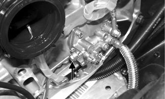
16. Connect the oil hose to the oil pump. Secure with the clamp. NOTE: After securing the oil hose to the oil pump, remove the bleed screw to allow any air in the hose/ pump to be released.
PC179A 17. Connect the MAG-side throttle body coolant hose; then secure with a clamp. 18. Connect the TPS; then lower the throttle body assembly into the engine compartment. 19. Place the throttle body assembly into position and secure with the flange clamps; then connect the gasline hose to the throttle body assembly and tighten the clamp securely.
20. Connect the PTO-side throttle body coolant hose; then secure with a clamp.
CAUTION
When installing the throttle bodies, make sure the gasline hose is properly routed to avoid premature wear and/or contact with exhaust components.
21. Fill the cooling system (see Liquid Cooling System in the Engine-Related Items section). 22. Install the oil injection control rod to the throttle body; then verify oil-injection pump synchronization (see the Fuel Systems section). 23. Using the existing clamps, secure the intake flanges to the throttle bodies. 24. With the air intake boot properly positioned on the throttle bodies, secure with the existing clamps. 25. Install the shock mount bracket support; then using new lock nuts, secure the support to the shock mount brackets and tighten to 20 ft-lb.
PC186A 26. Insert the servomotor cable ends into the slot in the clutch; then connect the servomotor connector.
Secure the cables with the holder.
PC187A 27. Rotate the servomotor clockwise to remove any slack from the cables; then install the servomotor retaining clip. Check APV cable adjustment (see
Arctic Power Valve (APV) System in the Engine-
Related Items section). 28. Install the PTO-side front spar and secure to the steering post and shock mount bracket using the existing cap screws. Tighten the cap screws to 25 ft-lb. 29. Install the fascia panels (with ECM) and secure to the chassis using the existing screws. Tighten securely. Connect the ECM. NOTE: At this point, secure the PDM harness to the shock mount bracket support using a cable tie. 30. Position the heat shield onto the two front locating pins (B); then secure it to the chassis with the two screws (A). Tighten securely.
PC189A 31. Install the resonator and secure with the springs; then place the expansion chamber and gaskets into position and secure to the exhaust manifold and resonator with the springs. NOTE: When installing the manifold springs, the long hook portion of the spring must be attached to the exhaust manifold or premature spring failure will result.
32. Install the exhaust temperature sensor into the expansion chamber. Tighten to 34 ft-lb. 33. Place the drive clutch with drive belt into position on the crankshaft and secure with the cap screw (threads coated with oil) and high-collar washer. Tighten to 51 ft-lb.
CAUTION
When installing the drive clutch, do not tighten the clutch cap screw with any kind of impact tool. Tighten cap screw using a hand torque wrench only. Failure to do so could result in stationary sheave damage.
NOTE: Before installing the drive clutch, be sure to wipe both the crankshaft and clutch mounting tapers clean using a clean towel.
34. Install the driven clutch on the driven shaft; then install the drive belt (see the Drive Train/Track/
Brake Systems section). 35. Install the driven clutch (see Driven clutch in the
Drive Train/Track/Brake Systems section); then check drive belt deflection (see the Drive Train/
Track/Brake Systems section). Install the rear belt guard. 36. Place the hood into position on the front end and secure with the screws; then install the hood harness.
Install the side access panels.
37. Start the engine and warm up to operating temperature; then verify that all components are functioning properly and that coolant is circulating through the cooling system properly.
CAUTION
Never run the engine with the hood harness disconnected or damage to the electrical system will result.
38. After running the engine to the proper operating temperature, shut the engine off; then open the access panels and inspect for any signs of coolant, gasoline, or oil leakage. 39. Allow the engine to cool; then check the coolant level and add coolant as necessary. Verify the tightening torque of the drive clutch.
CAUTION
If the engine had a major overhaul or if any major component was replaced, proper engine break-in procedures must be followed (see the General Information section) or severe engine damage may result.
Assembly Schematic - 8000
Torque Specification Tolerances Torque (ft-lb) Tolerance
0-15 ±20%
16-39 ±15%
40+ ±10%
800_12_1
800_12_2

This engine sub-section has been organized to show a progression for servicing of the Arctic Cat 6000 engine. For consistency purposes, this sub-section shows a complete and thorough progression; however, for efficiency it may be preferable to disassemble only those components needing to be addressed. Also, some components may vary from model to model. The technician should use discretion and sound judgment. SPECIAL TOOLS A number of special tools must be available to the technician when performing service procedures in this engine section.
Ball Hone Description
Flywheel Spanner Wrench Flywheel Puller Flywheel Puller Insert Extractor Nut (Medium) Oil Seal Protector Tool p/n
0644-294 0144-007 0744-040 0644-568 0643-074 0644-219
Piston Pin Puller
0644-328 Surface Plate 0644-016 Water Pump Bearing and Seal Tool Kit 0644-557 V Blocks 0644-535 Vacuum Test Pump 0644-131 NOTE: Special tools are available from the Arctic Cat Service Parts Department.
Disassembling
NOTE: When disassembling top-side components, mark MAG-side and PTO-side components for assembling purposes.
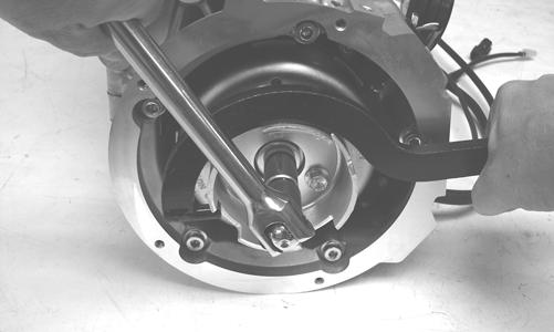
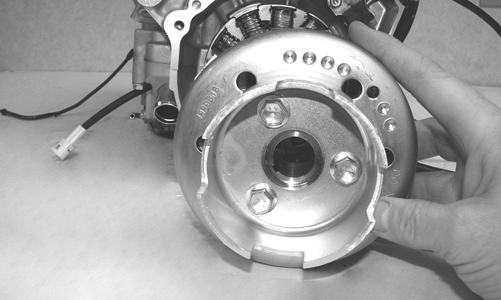
1. Using the Flywheel Spanner Wrench to secure the flywheel, remove the flywheel cap screw and washer; then remove the cap screws securing the recoil cup.
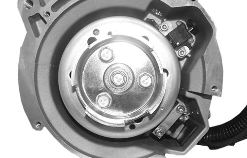
CWI-070
2. Install the Flywheel Puller Insert onto the end of the crankshaft.
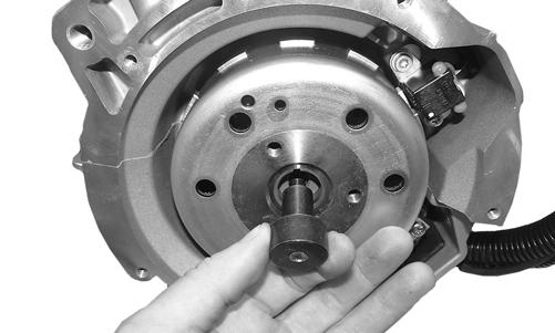
CWI-072 3. Using Flywheel Puller or suitable substitute, remove the flywheel from the crankshaft by tightening the puller bolt using an pneumatic gun. Account for the key.
CAUTION
To prevent damage to the crankshaft, do not thread puller bolts more than 1/2 in. into the flywheel. Damage to the stator may result.
NOTE: To ensure the cleanliness of the flywheel magnets, place the flywheel (with the magnets facing upward) on a clean bench.
4. Remove the cap screw securing the ground wire to the crankcase.
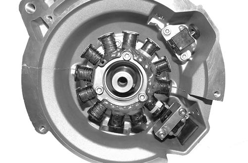
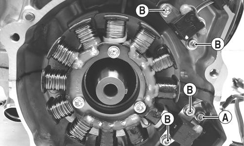
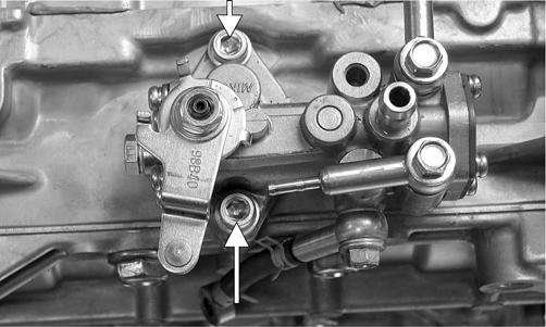
5. Remove the screw (A) securing the stator lead wire plate to the crankcase; then remove the screws (B) securing the timing sensors and bracket, remove the sensors, and account for the harness grommets.
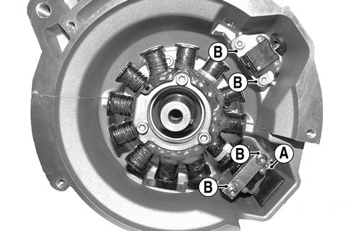
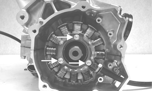
CWI-074A 6. Remove the screws securing the stator to the stator plate. Route the stator lead wire out of the crankcase; then remove the stator assembly.
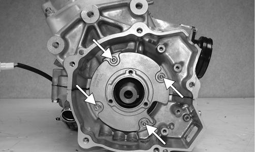
7. Remove the screws securing the stator plate to the engine; then remove the plate.
CWI-005A
NOTE: For assembling purposes, note the indentation (A) of the stator plate is aligned with the harness opening (B) in the crankcase.
CWI-005B
NOTE: The stator plate screws have Loctite applied to the threads during assembly. Using an impact driver, apply a sharp blow to the head of each screw to break the Loctite loose before removal.
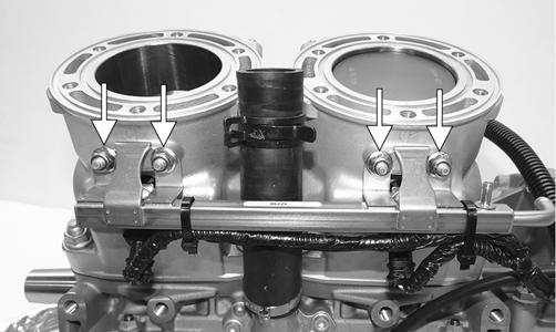
8. Remove the cap screws securing the APV assemblies to the cylinders; then remove the APV assemblies and set them aside. Account for all four dowel pins and make sure the pins do not fall into the engine.
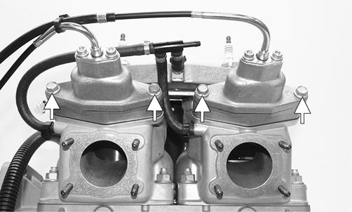
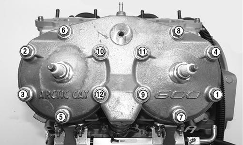
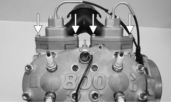
CWI-006A 9. Disconnect the coolant hose from the back of the cylinder head. 10. Remove the cap screws with O-rings securing the cylinder head (in the order shown); then separate the head from the cylinders. Account for the O-rings on top of the cylinders.
CWI-009
CWI-010 11. Remove the four nuts securing the fuel rail to the back of the cylinders; then remove the fuel rail and injectors as an assembly. Account for all gaskets.
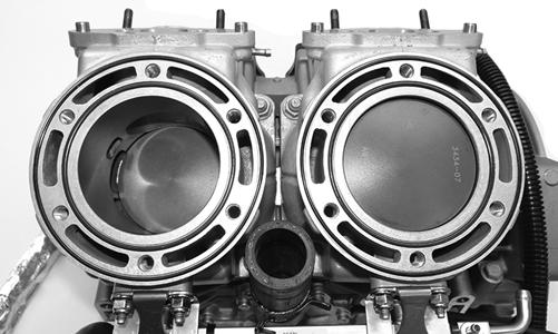
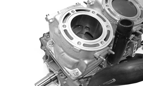
CWI-011A 12. Remove the eight nuts securing the cylinders to the crankcase; then using a soft hammer, gently tap the cylinders and remove from the crankcase by lifting them straight up off their studs. Account for a gasket and alignment pins.
CAUTION
When removing a cylinder, be sure to support the piston to prevent damage to the crankcase and piston.
CWI-012 13. Remove the PTO-side piston-pin circlip from the
PTO-side piston; then remove the MAG-side pistonpin circlip from the MAG-side piston.
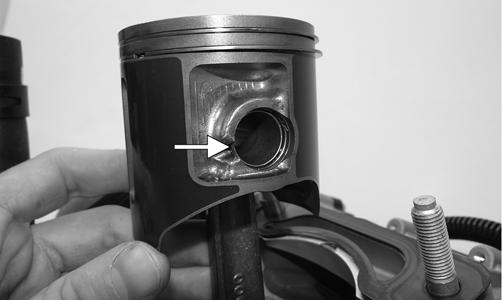
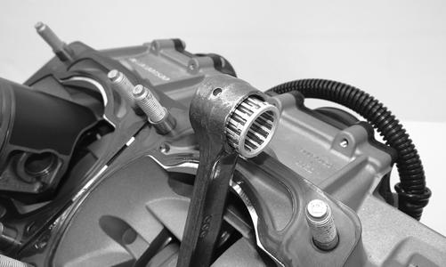
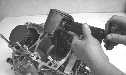
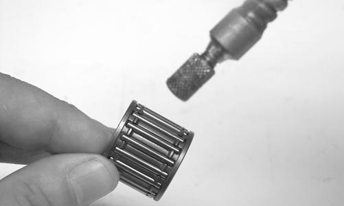
CWI-013A 14. Using Piston Pin Puller and medium Extractor Nut, remove the piston pins from both pistons. NOTE: For proper assembly, keep all MAG-side components and all PTO-side components separated. Assemble them on their proper sides.
CWI-014
CAUTION
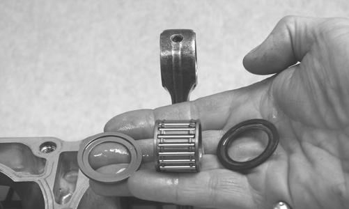
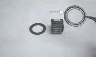
DO NOT use any type of punch to drive the piston pin free of the piston; damage may result. Use a piston-pin puller only. 15. Lift the pistons clear of the connecting rods and remove the small-end connecting-rod bearings; then remove the piston rings. Keep each piston with its rings; keep each piston pin and bearing together as a set.
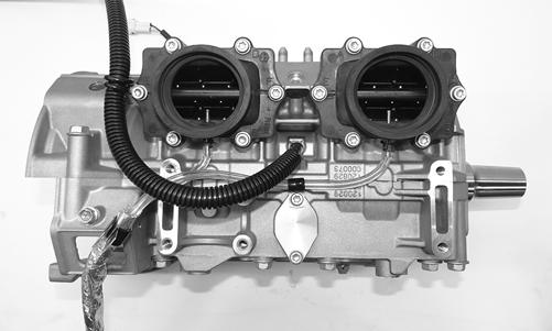
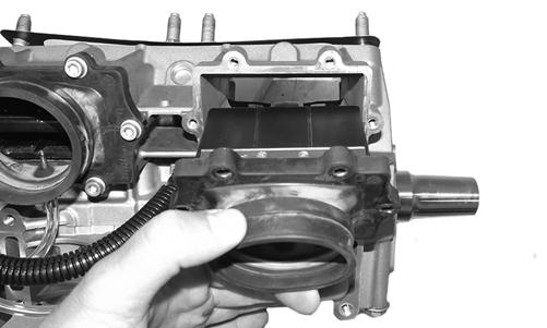
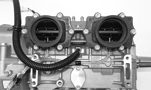
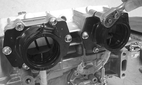
CWI-015 16. Remove the screws securing the intake flanges.
Remove the intake manifolds and reed valve assemblies.
CWI-020
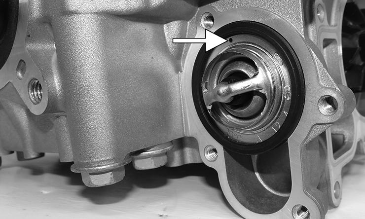
CWI-081 17. Remove the four screws securing the thermostat cap; then remove the cap, gasket, and thermostat.
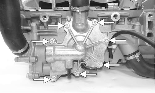
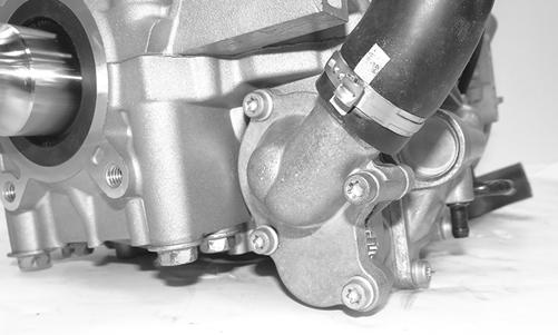
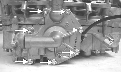
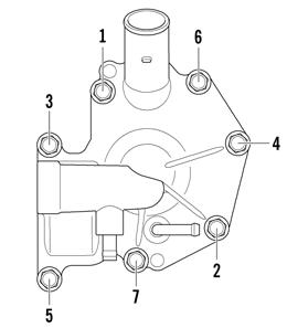
CWI-018A 18. Remove the seven screws securing the water pump cover to the crankcase and remove the cover.
Account for the O-ring gasket and the alignment pins.
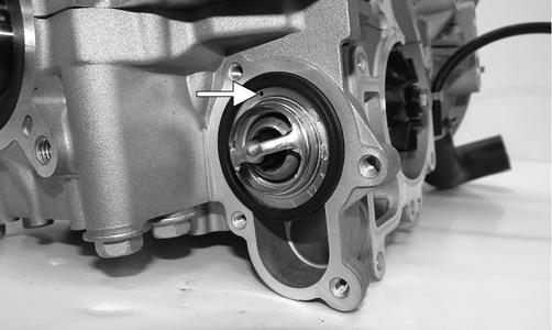
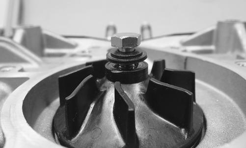
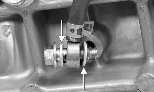
CWI-016A 19. Remove the cap screw securing the impeller. Account for the rubber washer and gasket behind the cap screw.
Remove the impeller from the shaft.
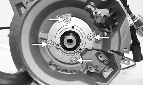
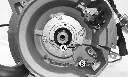
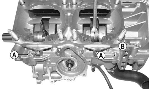
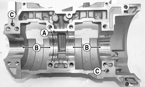
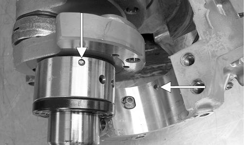
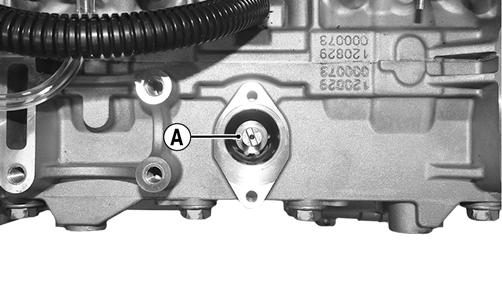
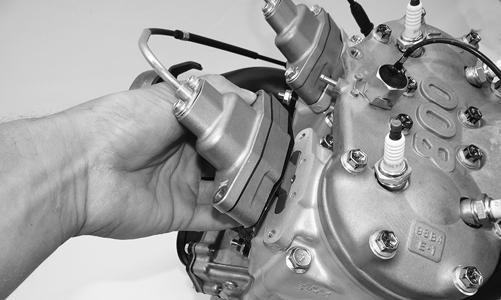
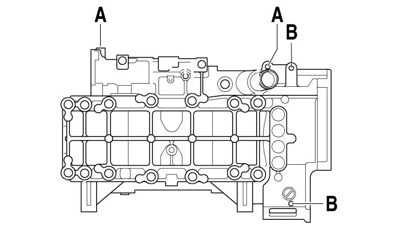
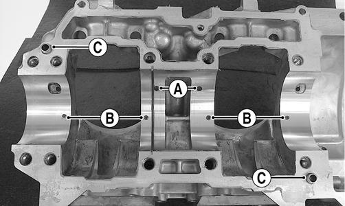
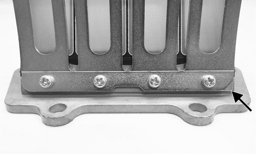
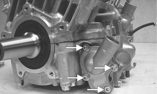
CWI-082 20. Prior to turning the engine upside down, remove the two crankcase torx screws (A) from the water pump side of the engine; then remove the two cap screws (B) from the magneto housing.
CWI-075A

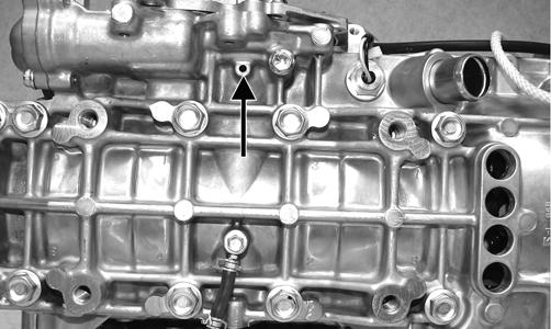
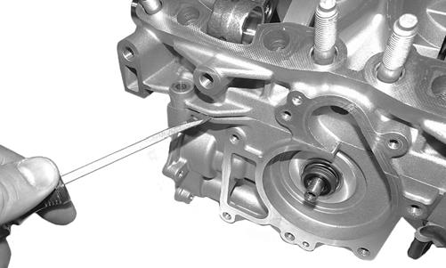
CWI-023A 21. Tip the crankcase assembly up onto the water pump side; then remove the black torx-screw from the bottom of the crankcase and tip down and drain the injection oil from the center cavity into a container.
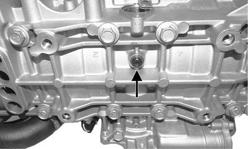
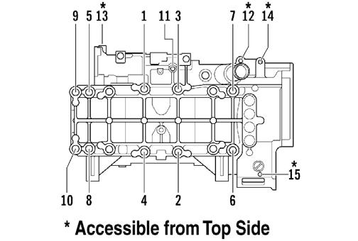
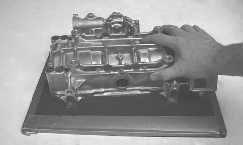
CWI-023A 22. With the bottom side up on two support blocks, remove the cap screws securing the crankcase halves.
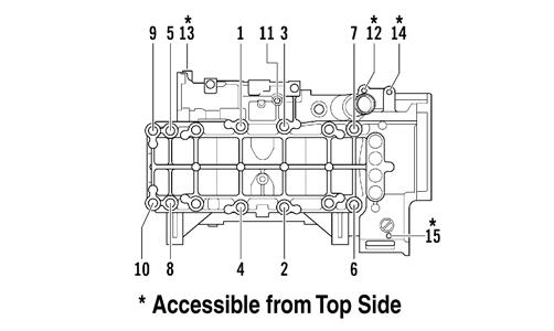
NOTE: Remove the cap screws in order from #10 to #1. The numbers are embossed next to each cap screw.

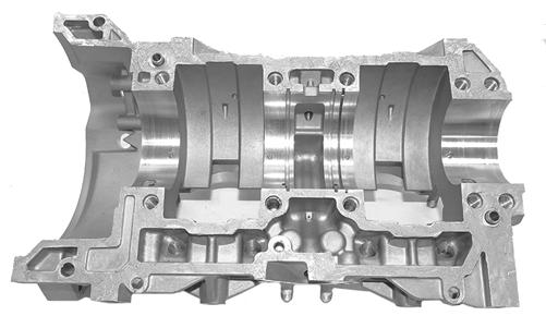
CWI-024 23. With all screws removed, carefully separate the crankcase halves in locations shown below only.
CWI-076
CAUTION
DO NOT drive any tool between halves (sealing surface) to separate the crankcase. Damage to the sealing surfaces will result.
24. Lift the bottom half of the crankcase off the top half.

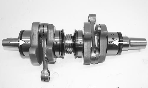
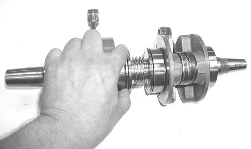
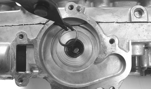
25. Lift the crankshaft free from the top half of the crankcase and slide the crankshaft bearings and oil seals off the crankshaft. Account for the C-ring (A).
Remove the bearing retaining pins (B) and account for the crankcase dowel pins (C).
CAUTION
Care must be taken to not allow the connecting rods to drop onto the sealing surface of the bottom case half.
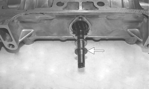
CWI-027A 26. Remove the water pump driveshaft from the lower crankcase half. Account for the thrust washer on the outer end of the shaft.
NOTE: When replacing the inner water pump seals, use the recommended Water Pump Bearing and Seal Tool Kit only.
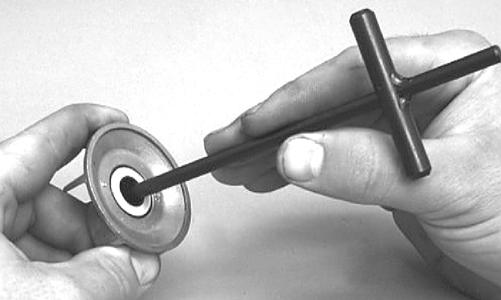
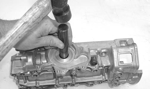
27. Place the lower crankcase on the bench with the water pump side down. Using the long seal driver, drive the mechanical water pump seal from the crankcase.
FC036 28. Using a pair of snap ring pliers, remove the snap ring securing the inner seal in the crankcase. 29. Using the hooked end of the tool, pull the inner seal free of the crankcase. 30. Using the hooked end of the tool, pry the seal ring from the backside of the water pump impeller.
AN327D
Cleaning and Inspecting
CYLINDER HEAD 1. Using a non-metallic carbon removal tool, remove any carbon buildup from the combustion chambers being careful not to nick, scrape, or damage the combustion chambers or the sealing surfaces. 2. Inspect the spark-plug holes for any damaged threads.
NOTE: If warpage is suspected, have a qualified machine shop inspect and repair if necessary.
3. Place the cylinder head on a Surface Plate covered with #400 grit wet-or-dry sandpaper. Using light pressure, move each cylinder head in a figure eight motion.
Inspect the sealing surface for any indication of high spots. A high spot can be noted by a bright metallic finish. Correct any high spots before assembly by continuing to move the cylinder head in a figure eight motion until a uniform bright metallic finish is attained.
CAUTION
Water or parts-cleaning solvent must be used in conjunction with the wet-or-dry sandpaper or damage to the sealing surface may result. CYLINDERS 1. Using a non-metallic carbon removal tool, remove carbon buildup from the exhaust ports. 2. Wash the cylinders in parts-cleaning solvent. 3. Inspect the cylinders for pitting, scoring, scuffing, and corrosion. If marks are found, repair the surface with the Ball Hone and honing oil. NOTE: To produce the proper 45° crosshatch pattern, maintain a low drill RPM. If honing oil is not available, use a lightweight, petroleum-based oil. Thoroughly clean the cylinders after honing using detergent soap and hot water and dry with compressed air; then immediately apply oil to the cylinder bores. If a bore is severely damaged or gouged, the cylinder must be replaced or replated.
4. Place the head surface of each cylinder on the surface plate covered with #400 grit wet-or-dry sandpaper. Using light pressure, move each cylinder in a figure eight motion. Inspect the surface for any indication of high spots. A high spot can be noted by a bright metallic finish. Correct any high spots before assembly by continuing to move the cylinder in a figure eight motion until a uniform bright metallic finish is attained.
CAUTION
Water or parts-cleaning solvent must be used in conjunction with the wet-or-dry sandpaper or damage to the sealing surface may result. PISTON 1. Using a non-metallic carbon removal tool, remove the carbon buildup from the dome of each piston. CRANKCASE 1. Scrape of any residual silicone from both the top and bottom crankcase halves making sure not to damage the sealing surface; then wash the crankcase halves in parts-cleaning solvent. NOTE: Before washing the crankcase halves, make sure the four bearing dowel pins have been removed and accounted for.
2. Inspect the crankcase halves for scoring, pitting, scuffing, or any imperfections in the casting. 3. Inspect all threaded areas for damaged or stripped threads. 4. Inspect the bearing areas for cracks or excessive bearing movement. If evidence of excessive bearing movement is noted, the crankcase must be replaced. 5. Inspect the bearing dowel pins for wear. 6. Inspect the sealing surfaces of the crankcase halves for trueness by placing each crankcase half on the surface plate covered with #400 grit wet-or-dry sandpaper. Using light pressure, move each half in a figure eight motion. Inspect the sealing surfaces for any indication of high spots. A high spot can be noted by a bright metallic finish. Correct any high spots by continuing to move the half in a figure eight motion until a uniform bright metallic finish is attained. NOTE: Care must be taken not to remove an excessive amount of aluminum, or the crankcase must be replaced. If excessive aluminum is removed, too much pre-load will be exerted on the crankshaft bearings when assembled.
CAUTION
Water or parts-cleaning solvent must be used in conjunction with the wet-or-dry sandpaper or damage to the sealing surface may result.
CRANKSHAFT
NOTE: If any servicing of the connecting rods, center bearings, or water pump drive gear is necessary, Arctic Cat recommends the crankshaft be taken to a qualified crankshaft rebuild shop for that service.
1. Wash the crankshaft with bearings in parts-cleaning solvent. 2. Inspect the bearings for wear, scoring, scuffing, damage, or discoloration. Rotate the bearings. Bearings must rotate freely and must not bind or feel rough. If any abnormal condition is noted, replace the bearing.
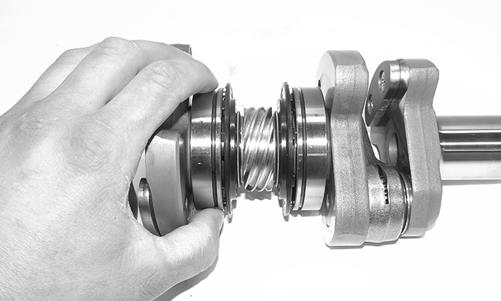
CWI-060 3. Inspect the connecting-rod bearings by rotating them. The bearings must rotate freely and must not bind or feel rough. If a connecting-rod bearing must be replaced, the connecting rod and crank pin must also be replaced.
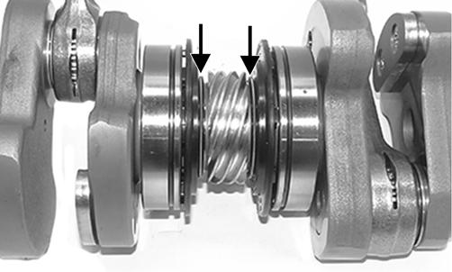
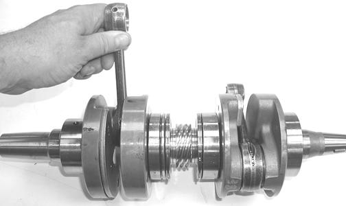
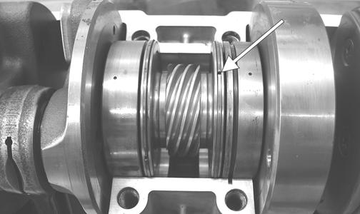
CWI-058 4. Visually inspect the springs to make sure they are in proper location on the seals.
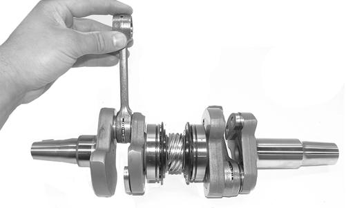
CWI-083A 5. Inspect the water pump drive gear for any signs of worn or chipped teeth. If either condition exists, replace the gear. NOTE: Lubricate bearings thoroughly prior to assembly.
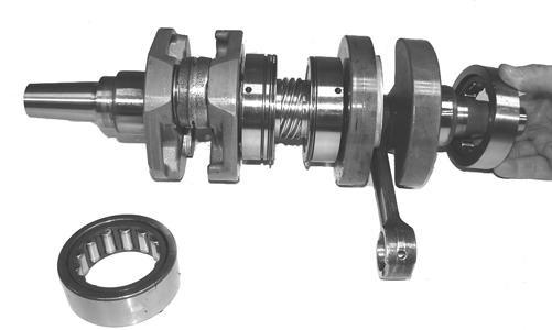
REMOVING/INSTALLING OUTER CRANKSHAFT BEARINGS
NOTE: The end bearings are not pressed onto the crankshaft. The bearings can be removed simply by sliding them off the crankshaft.
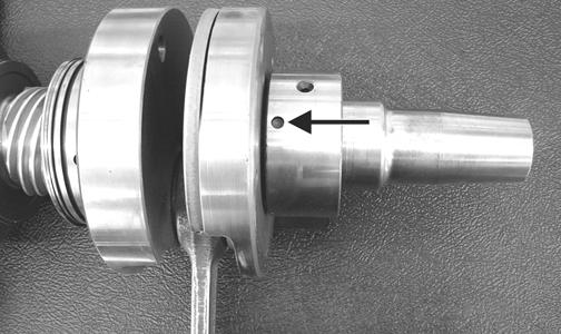
Inspect the crankshaft bearing area for wear. If any wear is noted on either end, replace the crankshaft end. NOTE: Install the bearings by sliding each bearing onto the crankshaft making sure the retaining pin hole (A) in the outer race of the bearing is properly positioned and will align with the retaining pin (B) in the crankcase.
IO019B
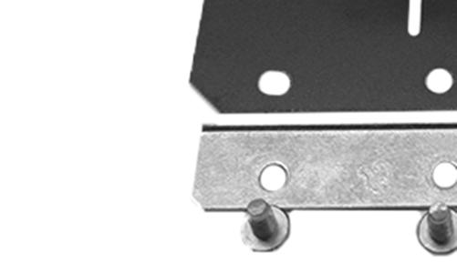
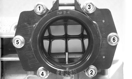
REED VALVE ASSEMBLY 1. Carefully pry the reed assemblies from the intake manifold and inspect the reed valves for cracks or any deterioration; then remove the screws securing the reeds.
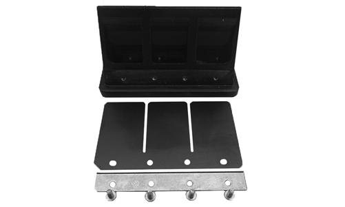
CWI-084 2. To assemble, place the reed retaining plate (with the lip facing outward) into position and secure with the screws tightened to 8.5 in.-lb. NOTE: When installing the outer reed valves, be sure the clipped edge matches the clipped edge of the reed retaining plate.
CWI-110 3. Install the reed valve assemblies into the intake manifold by installing the top and bottom sides of the reeds first; then press down making sure the reeds are installed flush with the intake manifold.
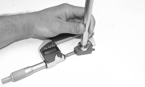
CWI-055 CWI-080 2. Position a bore gauge between the micrometer points and move it from top to bottom and side to side to find zero; then adjust the gauge to zero.
CWI-056
Measuring Critical Components
CYLINDER TRUENESS 1. Measure each cylinder in locations from front to back and side to side top and bottom of the cylinder for a total of four readings.
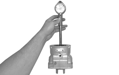
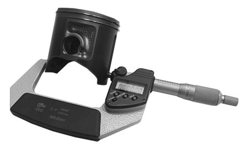
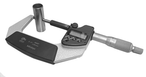
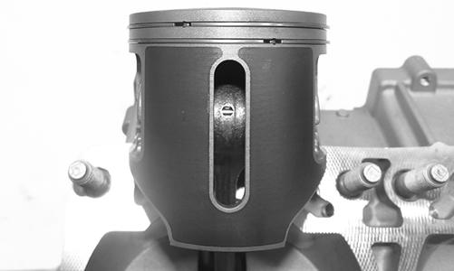
CWI-077 2. The trueness (out-of-roundness) is the difference between the highest and lowest reading. Maximum trueness (out-of-roundness) must not exceed 0.004 in. PISTON SKIRT/CYLINDER CLEARANCE 1. Measure the piston skirt diameter 10 mm from the bottom of the piston (just below the slot). Once the measurement is final, lock the micrometer.
CWI-090
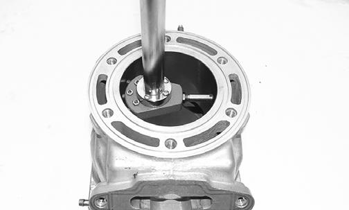
CWI-089 3. Place the bore gauge in the cylinder and measure each cylinder in locations from front to back and side to side top and bottom of the cylinder for a total of four readings. The difference (clearance) must be within 0.0031-0.0041 in.

CWI-086
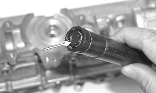
PISTON PIN Measure the piston pin diameter at each end and in the center. Acceptable piston pin measurement must be within 0.8659-0.8661 in. If any measurement varies by more than 0.001 in., the piston pin and bearing must be replaced as a set.
CWI-079
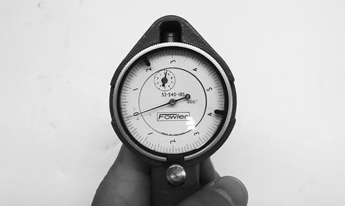
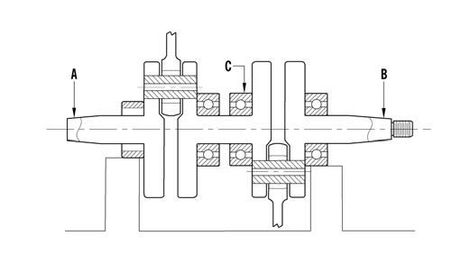
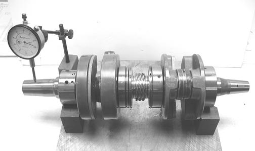
CRANKSHAFT RUNOUT 1. Using the V Blocks, support the crankshaft on the surface plate. NOTE: The V blocks should support the crankshaft on the middle bearings.
2. Mount a dial indicator and base on the surface plate.
Position the indicator contact point against the crankshaft location points C and D. Zero the indicator and rotate the crankshaft slowly. Note the amount of crankshaft runout (total indicator reading).
0747-810 3. If runout exceeds 0.002 in. at any of the checkpoints, the crankshaft must be either straightened or replaced.
Assembling
NOTE: The use of new gaskets and seals is recommended when assembling the engine.
NOTE: Prior to assembling the engine, use parts cleaning solvent and compressed air and thoroughly clean the threaded holes of the crankcase and cylinders to properly tighten.
NOTE: When the use of a lubricant is indicated, use Arctic Cat C-Tec2 engine oil.
! WARNING
Always wear safety glasses when drying components with compressed air.
1. Apply a thin coat of grease to the inner seal lips of the water pump seal. 2. Using the seal driver, position the inner water pump shaft seal onto the seal driver and gently tap the seal down into position. NOTE: Grease must be applied to the lips of the inner seal before installation.
MS986A
NOTE: The seal must be installed with its spring side towards the crankshaft.
3. Install the snap ring securing the inner seal in the crankcase. 4. Using the seal driver, carefully install the outer water pump seal. Gently tap the seal down into position until it seats itself against its flange. 5. Secure the upper crankcase half upside-down on a suitable support; then install the C-ring (A), the four bearing retaining pins (B), and the two crankcase dowel pins (C).
CWI-027A 6. Apply a thin coat of Loctite 5900 Sealant to the entire bottom half of the crankcase sealing surface.
CWI-030A 8. Install the crankshaft into the upper crankcase half.
Be sure the alignment hole in each bearing is positioned over its respective retaining pin in the crankcase; then seat the crankshaft.
IO019A
NOTE: To check the bearing for proper position, place the point of a sharp tool into the dimple found in the bearing race. Strike the tool with the palm of the hand in either direction. If the bearing moves, it isn’t positioned correctly and must be rotated until it drops onto the retaining pin.
CAUTION
If the bearings are not properly seated during assembly, the crankcase halves will not seal tightly and severe engine damage will result.
9. Assemble the crankcase halves; then install the crankcase cap screws securing the crankcase halves. 10. Tighten cap screws (1-10) in two steps using the pattern shown. First tighten to 15 ft-lb; then tighten to 33 ft-lb.
CWI-067 7. Place the crankshaft end bearings into position making sure the bearing retaining pin holes are positioned inward.
742-198A 11. Tighten screw 11 to 20 ft-lb; then turn the engine right-side up and tighten screws 12-15 in two steps to 102 in.-lb. 12. Apply a thin coat of grease to the sealing surface of the water pump shaft; then place the Oil Seal Protector Tool at the end of the shaft.
13. Rotate the water pump shaft while carefully pushing it through the oil and water pump seals until the driveshaft and crankshaft gears engage; then remove the oil seal protector tool (A) from the end of the shaft. CAUTION
Be very careful not to damage the seals when installing the oil pump driveshaft. Twist the driveshaft clockwise as it enters the seal area and while pushing it through the seals.
IO025A 14. Place the impeller into position and secure with the cap screw (threads coated with blue Loctite #243) and washers. Be sure the rubber side of the washer is lubricated with a light coat of grease and directed toward the impeller. Tighten to 102 in.-lb. 15. Apply a thin film of low-temp grease to the water pump cover O-ring; then position the O-ring into the water pump cover. With the alignment pins in place, install the cover. Secure with the screws using a crisscross pattern. Tighten to 102 in.-lb.
CAUTION
The rubber side of the washer securing the impeller must be positioned toward the impeller. If installed incorrectly, a coolant leak will result and engine damage may occur.
CWI-016A 16. Tip the crankcase assembly up on the water pump side; then pour Arctic Cat C-Tec2 engine oil into the center cavity of the crankshaft until the oil is level with the shoulder of the shaft (A).
CWI-016A
CAUTION
Failure to fill the center cavity of the crankcase assembly will result in center gear damage and engine failure.
NOTE: After the center cavity is filled with engine oil, be sure to install the hose with loom onto the upper crankcase half or engine oil will leak from that area.
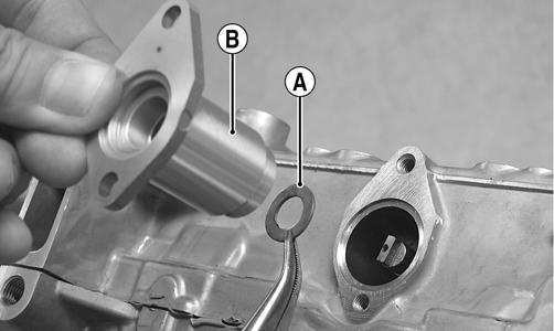
17. Position the shim on the retainer end of the pump shaft; then install the retainer with a new O-ring.
Tighten screws to 102 in.-lb. 18. Secure the reed valve assemblies and intake manifolds to the engine case using the existing screws.
Tighten in two steps to 115 in.-lb in order from the letter A to the letter F (embossed on the manifold).
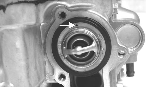
CWI-020 19. With the bypass/check valve of the thermostat directed to the 12 o’clock position, install the thermostat and housing; then in a crisscross pattern, tighten the screws to 102 in.-lb.
CWI-018A
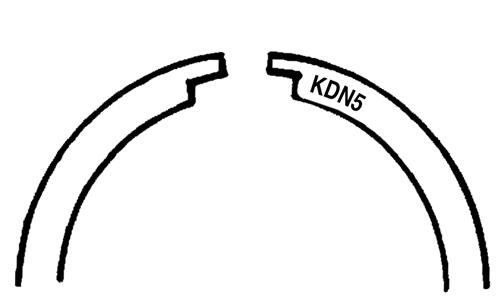
CWI-064 20. Install the dowel pins into the crankcase; then place the cylinder base gasket into position on the crankcase. 21. Install the piston rings on each piston so the letters
KDN5 on the top (inclined surface) of each ring faces the dome of the piston.
CWI-078A
CAUTION
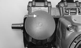
Incorrect installation of the piston rings will result in engine damage. 22. Apply oil to the connecting-rod small end bearings; then install the small-end bearings. 23. Place each piston over the connecting rod so the indicator arrow on each piston will point toward the exhaust ports; then secure with an oiled piston pin. NOTE: The indicator arrow is found on the piston dome.
24. Install the new circlips so the open end is directed either up or down.
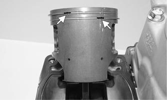
25. Rotate each piston ring until the ring ends are properly positioned on either side of the ring keeper; then apply oil to the piston assemblies and cylinder bores.
CAUTION
Make sure the circlips are firmly seated before continuing with assembly.
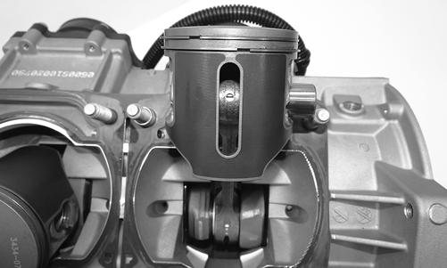
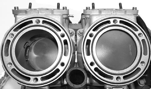
CWI-063 26. In turn on each cylinder, place a piston holder (or suitable substitute) beneath the piston skirt and square the piston in respect to the crankcase; then using a ring compressor or fingers, compress the rings and slide the cylinder over the piston. Remove the piston holder and seat the cylinder firmly onto the crankcase.
NOTE: The cylinders should slide on easily. DO NOT force the pistons into the cylinders.
27. Install each cylinder with the eight existing nuts; then secure the cylinders by tightening the cylinder base nuts to 15 ft-lb then to 38 ft-lb in a crisscross pattern. 28. Install the cylinder O-rings (lightly coated with oil) on the top of each cylinder making sure they are correctly positioned in the grooves.
CWI-010 29. Place new O-rings (lightly coated with oil) onto each of the head cap screws. Place four of these cap screws (from opposite end of each other) into the cylinder head. Thread the spark plugs in part way; then while holding the head above the cylinder, carefully start and finger-tighten all four cap screws while observing the cylinder O-rings to make sure they remain in position. Slowly place the head into position on top of the O-rings. NOTE: To install the remaining cap screws, the spark plugs must be removed.
30. Start and finger-tighten the cap screws being very careful not to move the cylinder head; then tighten the cap screws in two steps to 13 ft-lb then 28 ft-lb using the pattern shown.
0747-890
NOTE: At this point, install the spark plugs; then install the knock sensor. Tighten the sensor to 18 ftlb.
31. Install the coolant inlet hose to the cylinder head and water pump; then secure using the clamp. 32. Install the fuel rail assembly into the back of the cylinders making sure the gaskets are in place; then secure the rail using new nylon nuts. Tighten to 102 in.-lb.

CWI-008
NOTE: At this time if the coolant temperature sensor was removed, install the sensor (threads coated with blue Loctite #243) and tighten to 18 ft-lb.
NOTE: At this point, pressure test the engine (see the Engine-Related Items section).
33. With the raised edge of the valve aligned with the channel of the cylinder, slide the APV assemblies into position in the cylinders; then secure with cap screws. Tighten to 102 in.-lb. NOTE: The APV gaskets will align with the contour of the cylinder and APV assemblies when installed correctly. Be sure valves move freely after installing by pulling on the valve cable.
CWI-073
CWI-068 34. Secure the stator plate to the crankcase with the screws (coated with blue Loctite #243) and tightened to 102 in.-lb.
35. Route the stator harness through the opening in the crankcase; then secure the stator to the stator plate with the screws (coated with blue Loctite #243).
Tighten to 10 ft-lb. 36. Secure the upper ignition timing sensor with cap screws (coated with blue Loctite #243). Tighten to 53 in.-lb; then install the wiring grommet into the notch of the crankcase. 37. Secure the lower ignition timing sensor and bracket with two screws (coated with blue Loctite #243).
Tighten to 53 in.-lb; then install the grommet. With the stator harness properly positioned, install the plate and cap screw (coated with blue Loctite #243).
Tighten to 53 in.-lb.
CWI-074
38. Install the key in the crankshaft (if removed). NOTE: Before installing the flywheel, be sure to wipe the crankshaft and flywheel tapers clean using a clean, lint-free towel. 39. Place the recoil cup in position on the flywheel and visually center; then secure the cup with three cap screws and tighten only until snug. While holding the cup, slide the flywheel onto the crankshaft making sure the keyways match. 40. Apply red Loctite #271 to the threads of the flywheel cap screw with the large flat washer; then fingertighten only at this time into the crankshaft. 41. Secure the recoil cup while using the spanner wrench and tighten the three cap screws (from step 39) evenly to 18 ft-lb. 42. Using the spanner wrench, tighten the flywheel cap screw (from step 40) to 50 ft-lb.
CWI-070 43. Install the exhaust manifold with new gaskets and secure with the eight nuts. Tighten the nuts in a crisscross pattern to 12 ft-lb. 44. After installing the engine, bleed the oil lines using the Oil Bleeding Procedure included with the CATT
II Tool.
This engine sub-section has been organized to show a progression for servicing of the Arctic Cat 8000 engine. For consistency purposes, this sub-section shows a complete and thorough progression; however, for efficiency it may be preferable to disassemble only those components needing to be addressed. Also, some components may vary from model to model. The technician should use discretion and sound judgment. SPECIAL TOOLS A number of special tools must be available to the technician when performing service procedures in this engine section.
Ball Hone Description
Flywheel Spanner Wrench Flywheel Puller Flywheel Puller Insert Extractor Nut (Medium) Oil Seal Protector Tool p/n
0644-294 0144-007 0744-040 0644-568 0643-074 0644-219
Piston Pin Puller
0644-328 Surface Plate 0644-016 Water Pump Bearing and Seal Tool Kit 0644-557 V Blocks 0644-535 Vacuum Test Pump 0644-131 NOTE: Special tools are available from the Arctic Cat Service Parts Department.
Disassembling
NOTE: When disassembling top-side components, mark MAG-side and PTO-side components for assembling purposes.
1. Using the Flywheel Spanner Wrench to secure the flywheel, remove the flywheel cap screw and washer; then remove the three starter clutch cap screws and remove the clutch.
CM138 CM139 2. Install the Flywheel Puller Insert onto the end of the crankshaft.
IO013 3. Using Flywheel Puller or suitable substitute, remove the flywheel from the crankshaft by tightening the puller bolt, striking the head of the puller bolt with a hammer, and tightening again. Repeat this procedure until the flywheel is free. Account for the key.
CAUTION
To prevent damage to the crankshaft, do not thread puller bolts more than 1/2 in. into the flywheel. Damage to the coils may result.
CM140
NOTE: To ensure the cleanliness of the flywheel magnets, place the flywheel (with the magnets facing upward) on a clean bench.
4. Remove the cap screw securing the ground wire to the crankcase.
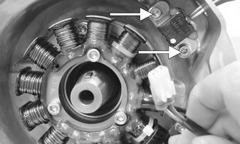
CM142A 5. Remove the Allen-head cap screw (A) securing the stator lead wire plate to the crankcase; then remove the Allen-head cap screws (B) securing the timing sensors, remove the sensors, and account for the harness grommets.
CM141C 6. Remove the Allen-head cap screws securing the stator to the stator plate. Route the stator lead wire out of the crankcase; then remove the stator assembly.
CM143A
7. Remove the cap screws securing the stator plate to the engine; then remove the plate.
CM145D
NOTE: For assembling purposes, note the indentation (A) of the stator plate is aligned with the harness opening (B) in the crankcase.

CM145C
NOTE: The stator plate screws had Loctite applied to the threads during assembly. Using an impact driver, apply a sharp blow to the head of each screw to break the Loctite loose before removal.
8. Remove the cap screws securing the APV assemblies to the cylinders; then remove the APV assemblies and set them aside.
NOTE: For assembling purposes, note that the APV exhaust valves and gaskets are directional and marked (M) for magneto cylinder and (P) for PTO cylinder.
XM024A
XM017
9. Remove the spark plugs. NOTE: At this point, remove the knock sensor and lock plate from the cylinder head by bending the lock plate tabs down and unthreading the sensor.
10. Remove the cap screws with O-rings securing the cylinder head; then separate from the cylinders.
Account for the O-rings.
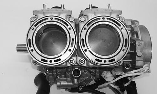
XM022
NOTE: When removing the cylinders, place the engine on its intake flanges on a drain tray to allow residual coolant to drain from the cylinder/crankcase water jacket.
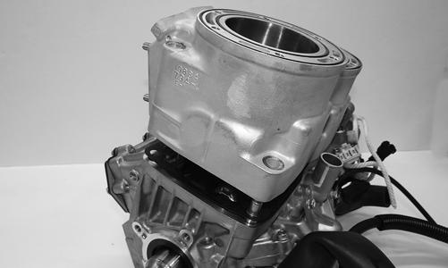
11. Remove the four nuts and four cap screws securing the cylinders to the crankcase; then using a soft hammer, gently tap the cylinders and remove from the crankcase by lifting them straight up off their studs.
Account for gasket(s) and alignment pins.
CAUTION
When removing a cylinder, be sure to support the piston to prevent damage to the crankcase and piston.
XM018 12. Remove the PTO-side piston-pin circlip from the
PTO-side piston; then remove the MAG-side pistonpin circlip from the MAG-side piston.
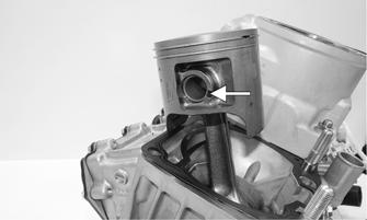
XM020A 13. Using Piston Pin Puller and medium Extractor Nut, remove the piston pins from both pistons. NOTE: For proper assembly, keep all MAG-side components and all PTO-side components separated. Assemble them on their proper sides.
CM150
CAUTION
DO NOT use any type of punch to drive the piston pin free of the piston; damage may result. Use a piston-pin puller only. 14. Lift the pistons clear of the connecting rods and remove the small-end connecting-rod bearings (account for two washers); then remove the piston rings. Keep each piston with its rings; keep each piston pin and bearing together as a set.
CM151
NOTE: Place a suitable length of rubber hose around the connecting rods to prevent the connecting rods from damaging the crankcase.
15. Disconnect the intake flange oil lines from the oil pump; then remove the cap screws securing the intake flanges. Remove the intake flanges and reed valve assemblies.
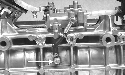
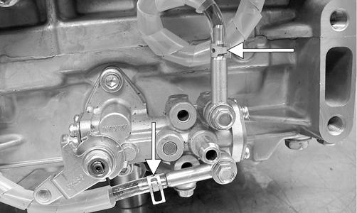
IO014 16. Remove the lower union cap screw securing the lower check valve assembly to the crankcase; then remove the two screws securing the oil-injection pump to the crankcase. Remove the pump, retainer, and O-ring and account for the two gaskets from the lower union.
CM153A IO015A 17. Remove the four cap screws securing the thermostat cap; then remove the cap, gasket, and thermostat.

IO017A
NOTE: For assembling purposes, note that the positioning of the bypass/check valve is directed up.
CM157A 18. Remove the seven screws securing the water pump cover to the crankcase and remove the cover.
Account for the O-ring gasket and the alignment pins.
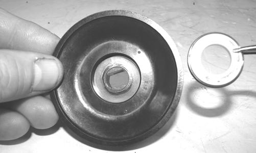
CM156A 19. Remove the cap screw securing the water pump impeller; then slide the impeller free of the shaft.
Account for the washer and gasket.

IO018A 20. Prior to turning the engine upside down, remove the two crankcase cap screws (A) from the water pump side of the engine; then remove the two cap screws (B) from the magneto housing.
742-198B 21. Turn the engine upside down on support blocks, cut the cable tie, and remove the coolant temperature sensor switch. 22. With its bottom side up on two support blocks, remove the cap screws securing the crankcase halves. 23. Separate the crankcase halves by installing two crankcase cap screws in opposite corners leaving the heads approximately 1/4 in. out. Using a plastic hammer and lifting on the ends of the crankshaft, tap on each cap screw head until the case halves separate.
Remove the cap screws.
DO NOT drive any tool between halves to separate the crankcase. Damage to the sealing surfaces will result.

CM158 24. Lift the bottom half of the crankcase off the top half.
25. Lift the crankshaft free from the top half of the crankcase and slide the crankshaft oil seals off the crankshaft. Account for the C-ring (A). Remove the bearing retaining pins (B) and account for the crankcase dowel pins (C).
CAUTION
Care must be taken to not allow the connecting rods to drop onto the sealing surface of the bottom case half.
IO023A
NOTE: The end bearings are not pressed onto the crankshaft. After removing the seals, use care not to allow the bearings to slide off the crankshaft.
26. Remove the oil-injection pump/water pump driveshaft from the lower crankcase half. Account for the thrust washer on the outer end of the shaft.
CM159A
NOTE: When replacing the inner water pump seals, use the recommended Water Pump Bearing and Seal Tool Kit only.
27. Place the crankcase on the bench with the water pump side down. Using the long seal driver, drive the mechanical water pump seal from the crankcase.
FC036 28. Using a pair of snap ring pliers, remove the snap ring securing the inner seal in the crankcase. 29. Using the hooked end of the tool, pull the inner seal free of the crankcase. 30. Using the hooked end of the tool, pry the seal ring from the backside of the water pump impeller.
AN327D CYLINDER HEAD 1. Using a non-metallic carbon removal tool, remove any carbon buildup from the combustion chambers being careful not to nick, scrape, or damage the combustion chambers or the sealing surfaces. 2. Inspect the spark-plug holes for any damaged threads.
NOTE: If warpage is suspected, have a qualified machine shop inspect and repair if necessary.
3. Place the cylinder head on a Surface Plate covered with #400 grit wet-or-dry sandpaper. Using light pressure, move each cylinder head in a figure eight motion.
Inspect the sealing surface for any indication of high spots. A high spot can be noted by a bright metallic finish. Correct any high spots before assembly by continuing to move the cylinder head in a figure eight motion until a uniform bright metallic finish is attained.
CAUTION
Water or parts-cleaning solvent must be used in conjunction with the wet-or-dry sandpaper or damage to the sealing surface may result. CYLINDERS 1. Using a non-metallic carbon removal tool, remove carbon buildup from the exhaust ports. 2. Wash the cylinders in parts-cleaning solvent. 3. Inspect the cylinders for pitting, scoring, scuffing, and corrosion. If marks are found, repair the surface with the Ball Hone and honing oil. NOTE: To produce the proper 45° crosshatch pattern, maintain a low drill RPM. If honing oil is not available, use a lightweight, petroleum-based oil. Thoroughly clean the cylinders after honing using detergent soap and hot water and dry with compressed air; then immediately apply oil to the cylinder bores. If a bore is severely damaged or gouged, the cylinder must be replaced.
4. Place the head surface of each cylinder on the surface plate covered with #400 grit wet-or-dry sandpaper. Using light pressure, move each cylinder in a figure eight motion. Inspect the surface for any indication of high spots. A high spot can be noted by a bright metallic finish. Correct any high spots before assembly by continuing to move the cylinder in a figure eight motion until a uniform bright metallic finish is attained.
CAUTION
Water or parts-cleaning solvent must be used in conjunction with the wet-or-dry sandpaper or damage to the sealing surface may result.
PISTON ASSEMBLY 1. Using a non-metallic carbon removal tool, remove the carbon buildup from the dome of each piston. 2. Snap an old piston ring into two pieces; then grind the end of the old ring to a 45° angle and to a sharp edge. Using the sharpened ring as a tool, clean carbon from the ring-grooves. Be sure to position the ring with its tapered side up.
CAUTION
Improper cleaning of the ring-grooves by the use of the wrong type of ring-groove cleaner will result in severe damage to the piston.
3. Inspect each piston for cracks in the piston pin and skirt areas. 4. Inspect each piston for seizure marks or scuffing.
Repair with #400 grit wet-or-dry sandpaper and water or honing oil. NOTE: If scuffing or seizure marks are too deep to correct with the sandpaper, it will be necessary to replace the piston.
5. Inspect the perimeter of each piston for signs of excessive “blowby.” Excessive “blowby” indicates worn piston rings or an out-of-round cylinder. NOTE: If synthetic oil is being used, a certain amount of “blowby” may be visible under normal use.
CRANKCASE 1. Wash the crankcase halves in parts-cleaning solvent. NOTE: Before washing the crankcase halves, make sure the four bearing dowel pins have been removed and accounted for.
2. Inspect the crankcase halves for scoring, pitting, scuffing, or any imperfections in the casting. 3. Inspect all threaded areas for damaged or stripped threads. 4. Inspect the bearing areas for cracks or excessive bearing movement. If evidence of excessive bearing movement is noted, the crankcase must be replaced. 5. Inspect the bearing dowel pins for wear. 6. Inspect the sealing surfaces of the crankcase halves for trueness by placing each crankcase half on the surface plate covered with #400 grit wet-or-dry sandpaper. Using light pressure, move each half in a figure eight motion. Inspect the sealing surfaces for any indication of high spots. A high spot can be noted by a bright metallic finish. Correct any high spots by continuing to move the half in a figure eight motion until a uniform bright metallic finish is attained. NOTE: Care must be taken not to remove an excessive amount of aluminum, or the crankcase must be replaced. If excessive aluminum is removed, too much pre-load will be exerted on the crankshaft bearings when assembled.
CM160
CAUTION
Water or parts-cleaning solvent must be used in conjunction with the wet-or-dry sandpaper or damage to the sealing surface may result.
CRANKSHAFT
NOTE: If any servicing of the connecting rods, center bearings, or oil-injection pump drive gear is necessary, Arctic Cat recommends the crankshaft be taken to a qualified machine shop for that service.
1. Wash the crankshaft with bearings in parts-cleaning solvent. 2. Inspect the bearings for wear, scoring, scuffing, damage, or discoloration. Rotate the bearings. Bearings must rotate freely and must not bind or feel rough. If any abnormal condition is noted, replace the bearing.
FC039 3. Inspect the connecting-rod bearings by rotating them. The bearings must rotate freely and must not bind or feel rough. If a connecting-rod bearing must be replaced, the connecting rod and crank pin must also be replaced.
FC040 4. Inspect the oil-injection pump drive gear for any signs of worn or chipped teeth. If either condition exists, replace the gear. NOTE: Lubricate bearings thoroughly prior to assembly.
REMOVING/INSTALLING OUTER CRANKSHAFT BEARINGS
NOTE: The end bearings are not pressed onto the crankshaft. The bearings can be removed simply by sliding them off the crankshaft.
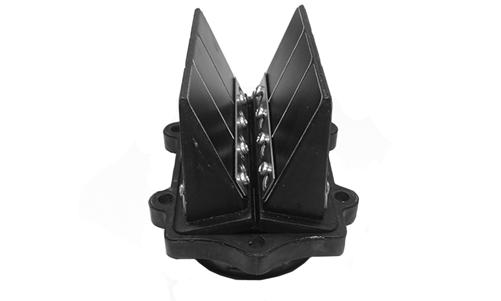
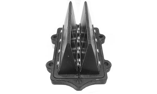
CM161 Inspect the crankshaft bearing area for wear. If any wear is noted on either end, replace the crankshaft end. NOTE: Install the bearings by sliding each bearing onto the crankshaft making sure the retaining pin hole (A) in the outer race of the bearing is properly positioned and will align with the retaining pin (B) in the crankcase. REED VALVE ASSEMBLY 1. Inspect the reed valves, stoppers, and valve blocks for cracks or any deterioration.
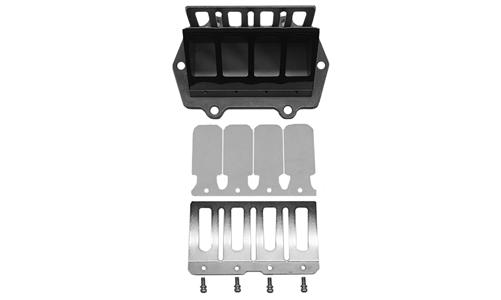
XM227 2. Wash the reed valves, stopper, and cage assembly in parts-cleaning solvent and blow dry. 3. Inspect the reed stopper height. Using a caliper, measure the distance from the seat to the bottom outer tip edge of the stopper. Measurement must not exceed specifications. If measurement is not within specifications, either bend or replace the reed stopper.
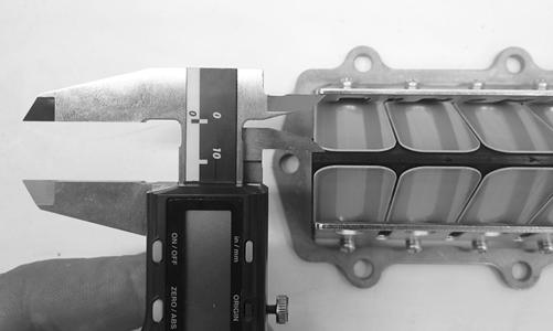
XM226 4. Inspect the reed-to-seat clearance. Using a feeler gauge, measure the clearance. Clearance must be less than 0.008in. If clearance is not within specifications, replace the reed valve. 5. To assemble, place the reed valves on the cage with its clipped corner positioned to the lower right hand corner of the cage. Place the reed stopper assembly into position and secure with the screws tightened to 8.5 in.-lb.
Measuring Critical Components
CYLINDER TRUENESS 1. Measure each cylinder in locations from front to back and side to side top and bottom of the cylinder for a total of four readings.
CWI-077 2. The trueness (out-of-roundness) is the difference between the highest and lowest reading. Maximum trueness (out-of-roundness) must not exceed 0.004 in. PISTON SKIRT/CYLINDER CLEARANCE 1. Measure the piston skirt diameter 10 mm from the bottom of the piston. Once the measurement is final, lock the micrometer. 2. Position a bore gauge between the micrometer points and move it from top to bottom and side to side to find zero; then adjust the gauge to zero.
CWI-090 CWI-089 3. Place the bore gauge in the cylinder and measure each cylinder in locations from front to back and side to side top and bottom of the cylinder for a total of four readings. The difference (clearance) must be within 0.0031-0.0041 in.
CWI-087
CWI-086
PISTON PIN Measure the piston pin diameter at each end and in the center. Acceptable piston pin measurement must be within 0.8659-0.8661 in. If any measurement varies by more than 0.001 in., the piston pin and bearing must be replaced as a set.
CWI-079
CRANKSHAFT RUNOUT 1. Using the V Blocks, support the crankshaft on the surface plate. NOTE: The V blocks should support the crankshaft on the outer bearings.
2. Mount a dial indicator and base on the surface plate.
Position the indicator contact point against the crankshaft location point A (PTO-end) from the crankshaft end. Zero the indicator and rotate the crankshaft slowly. Note the amount of crankshaft runout (total indicator reading).
0742-727
NOTE: For runout location point specifications, see Crankshaft Runout/Repair Specifications in the General Information section of this manual.
3. Position the indicator contact point against the crankshaft location point B (MAG-end) from the crankshaft end. Zero the indicator and rotate the crankshaft slowly. Note the amount of crankshaft runout (total indicator reading).
FC046 4. Position the indicator contact point against the crankshaft at location point C (center). Zero the indicator and rotate the crankshaft slowly. Note the amount of crankshaft runout (total indicator reading). 5. If runout exceeds 0.002 in. at any of the checkpoints, the crankshaft must be either straightened or replaced.
Assembling
NOTE: The use of new gaskets and seals is recommended when assembling the engine.
NOTE: Prior to assembling the engine, use parts cleaning solvent and compressed air and thoroughly clean the threaded holes of the crankcase and cylinders to properly tighten.
NOTE: When the use of a lubricant is indicated, use Arctic Cat Synthetic APV 2-Cycle Oil.
! WARNING
Always wear safety glasses when drying components with compressed air.
1. Apply a thin coat of grease to the inner seal lips of the water pump seal. 2. Using the seal driver, position the inner water pump shaft seal onto the seal driver and gently tap the seal down into position. NOTE: Grease must be applied to the lips of the inner seal before installation.
3. Install the snap ring securing the inner seal in the crankcase.
MS415 4. Using the seal driver, carefully install the outer water pump seal. Gently tap the seal down into position until it seats itself against its flange.
MS988
5. Secure the upper crankcase half upside-down on a suitable support; then install the C-ring (A), the four bearing retaining pins (B), and the two crankcase dowel pins (C).
IO023A 6. Place the crankshaft end bearings into position making sure the bearing retaining pin hole is positioned inward.
CM043A 7. Lubricate the inner lips of the crankshaft oil seals with grease; then slide the seals onto the crankshaft making sure the spring side of each seal faces inward. 8. Apply oil to the crankshaft bearings; then install the crankshaft into the upper crankcase half. Be sure the alignment hole in each bearing is positioned over its respective retaining pin in the crankcase; then seat the crankshaft.
IO019A
NOTE: To check the bearing for proper position, place the point of a sharp tool into the dimple found in the bearing race. Strike the tool with the palm of the hand in either direction. If the bearing moves, it isn’t positioned correctly and must be rotated until it drops onto the retaining pin.
CAUTION
If the bearings are not properly seated during assembly, the crankcase halves will not seal tightly and severe engine damage will result.
9. Position the two center seal rings with their end gaps 180° apart (up on one and down on the other); then apply a thin coat of High-Temp Sealant to the entire bottom half of the crankcase sealing surface.
CM036A
CM166 10. Assemble the crankcase halves making sure the crankshaft gear and oil-injection pump driveshaft gears mesh. Rotate the crankshaft one full turn to align the crankshaft gear and pump driveshaft. 11. Install the crankcase cap screws securing the crankcase halves. 12. Tighten cap screws (1-10) in two steps from 13 ft-lb to 31 ft-lb using the pattern shown.
742-198A 13. Tighten cap screw (11) to 96 in.-lb; then turn the engine right-side up and tighten cap screws (12-15) in two steps to 25 ft-lb. 14. Apply a thin coat of grease to the sealing surface of the oil-injection pump/water pump driveshaft; then place the Oil Seal Protector Tool at the end of the shaft.
CAUTION
Be very careful not to damage the seals when installing the oil pump driveshaft. Twist the driveshaft clockwise as it enters the seal area and while pushing it through the seals.
FS191 15. Rotate the oil-injection pump/water pump driveshaft while carefully pushing it through the oil and water pump seals until the driveshaft and crankshaft gears engage; then remove the oil seal protector tool (A) from the end of the shaft.
IO025A 16. Position the shim (A) on the oil-injection pump end of the driveshaft; then install the oil-injection pump retainer (B) with a new O-ring.
IO026A
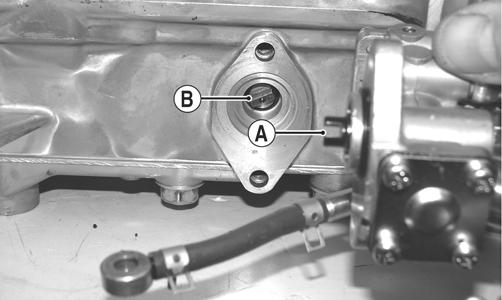
17. With the new O-ring (lightly coated with oil) in place, install the oil-injection pump making sure the pump shaft slot (A) and pump driven gear shaft (B) align. Secure with two screws (coated with blue Loctite #243). Tighten the two screws to 96 in.-lb.
CM167A
CAUTION
Be sure the oil-injection pump/water pump driveshaft is properly aligned with the slot of the oil-injection pump. The pump will be damaged if these two components are not aligned. 18. Place the lower union assembly (with new gaskets) into position and secure with the gaskets and union cap screw. Tighten to 48 in.-lb.
CM153A
IO020A
CAUTION
Always use new gaskets and assure that a gasket is in place on each side of the union prior to securing the union cap screw to the crankcase. 19. With new gaskets, install the reed valve assemblies and intake flanges using the pattern shown. Tighten to 96 in.-lb; then secure the intake flange oil hoses to the oil pump and secure with the clamps.
IO021A
IO022A 20. Install the coolant temperature sensor (threads coated with white Loctite #575) and tighten to 18 ft-lb; then secure the sensor wire to the sensor with a cable tie. 21. Position the ceramic/rubber seal into the back side of the water pump impeller with the ceramic face of the seal directed out.
CM168 22. Using a suitable tool, press the seal into position making sure its marked side is positioned towards the rubber seal cup; then apply a thin coat of grease to the seal outer surface.
CAUTION
When installing the ceramic/rubber seal into the impeller, never touch the ceramic part of the seal. Make sure components are clean and free of any dirt or contaminants.
23. Place the impeller into position and secure with a cap screw and washer. Be sure the rubber side of the washer is lubricated with a light coat of grease and directed toward the impeller. Apply blue Loctite #243 to the threads of the cap screw and tighten to 108 in.-lb.
IO018A
CAUTION
The rubber side of the washer securing the impeller must be positioned toward the impeller. If installed incorrectly, a coolant leak will result. 24. Apply High-Temp Sealant to the crankcase/water pump cover seam; then install the dowel pins into the crankcase. 25. Apply a thin film of low-temp grease to the water pump cover O-ring; then position the O-ring into the water pump cover. With the alignment pins in place, install the cover. Secure with the screws using the pattern shown. Tighten to 96 in.-lb.
0742-257 26. With the bypass valve of the thermostat directed to the 12 o’clock position, install the thermostat and housing; then in a crisscross pattern, tighten the cap screws to 96 in.-lb.
CM157A
CM155A 27. Install the dowel pins into the crankcase; then place the cylinder base gasket into position on the crankcase. 28. Install the piston rings on each piston so the letter on the top (inclined surface) of each ring faces the dome of the piston.

726-306A
CAUTION
Incorrect installation of the piston rings will result in engine damage. 29. Apply oil to the connecting-rod small end bearings; then install the small-end bearings. Install a washer on each side of the connecting rod.
TZ068
NOTE: The shoulder side of the washer must seat to the needle bearing.
CM172A 30. Place each piston over the connecting rod so the indicator dot on each piston will point toward the intake/ exhaust ports; then secure with an oiled piston pin. NOTE: The indicator dot is found on the piston dome.
XM019A 31. Install the new circlips so the open end is directed either up or down.
32. Rotate each piston ring until the ring ends are properly positioned on either side of the ring keeper; then apply oil to the piston assemblies and cylinder bores.
CAUTION
Make sure the circlips are firmly seated before continuing with assembly.
XM021A 33. In turn on each cylinder, place a piston holder (or suitable substitute) beneath the piston skirt and square the piston in respect to the crankcase; then using a ring compressor or fingers, compress the rings and slide the cylinder over the piston. Remove the piston holder and seat the cylinder firmly onto the crankcase.
NOTE: The cylinders should slide on easily. DO NOT force the pistons into the cylinders.
XM018 34. Install each cylinder with the four nuts and four new cap screws; then secure the cylinders by tightening the cylinder base nuts and cap screws to 44 ft-lb in three steps using the pattern shown.
0738-206
NOTE: Always use new cap screws when installing the cylinders.
35. Install the two cylinder O-rings (lightly coated with oil) on the top of each cylinder making sure they are correctly positioned in the grooves.
XM022 36. Place new O-rings (lightly coated with oil) onto each of the head cap screws. Place four of these cap screws (from opposite end of each other) into the cylinder head. Thread the spark plugs in part way; then while holding the head above the cylinder, carefully start and finger-tighten all four cap screws while observing the cylinder O-rings to make sure they remain in position. Slowly place the head into position on top of the O-rings.
XM016
NOTE: To install the remaining cap screws, the spark plugs must be removed.
37. Start and finger-tighten the remaining cap screws being very careful not to move the cylinder head; then tighten the cap screws in two steps to 25 ft-lb using the pattern shown.
0742-200
NOTE: At this point, install the spark plugs; then install the knock sensor with the new lock plate, tighten the sensor to 17 ft-lb, and bend the lock plate tabs up. 38. With the raised edge of the valve aligned with the channel of the cylinder, slide the APV assemblies into position in the cylinders; then secure with cap screws. Tighten to 96 in.-lb.
XM017 39. Secure the stator plate to the crankcase with the
Allen-head cap screws (coated with blue Loctite #243) and tightened to 96 in.-lb. 40. Route the stator harness through the opening in the crankcase; then secure the stator to the stator plate with the Allen-head cap screws (coated with blue
Loctite #243). Tighten to 96 in.-lb.
CM143A 41. Secure the upper ignition timing sensor (white dot/ connector) with cap screws (coated with blue Loctite #243). Tighten to 48 in.-lb; then install the wiring grommet into the notch of the crankcase.
IO049A
42. Secure the lower ignition timing sensor with two cap screws (A) (coated with blue Loctite #243). Tighten to 48 in.-lb; then install the grommet. With the stator harness properly positioned, install the plate and cap screw (B) (coated with blue Loctite #243). Tighten to 48 in.-lb.
CM177A
43. Install the key in the crankshaft. 44. Place the starter clutch in position on the flywheel; then secure the starter clutch with three cap screws and tighten only until snug. While holding the starter clutch, slide the flywheel onto the crankshaft making sure the keyways match.
CM180
NOTE: Before installing the flywheel, be sure to wipe the crankshaft and flywheel tapers clean using a clean, lint-free towel.
45. Apply red Loctite #271 to the threads of the flywheel cap screw; then finger-tighten with a large flat washer. DO NOT TIGHTEN AT THIS TIME. 46. Secure the starter clutch while using the spanner wrench and tighten the three cap screws (from step 45) evenly to 19 ft-lb.

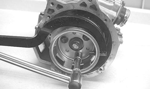
FC081 47. Using the spanner wrench, tighten the flywheel cap screw (from step 45) to 50 ft-lb. 48. Install the coolant inlet hose to the cylinder head and water pump; then tighten the hose clamps securely.
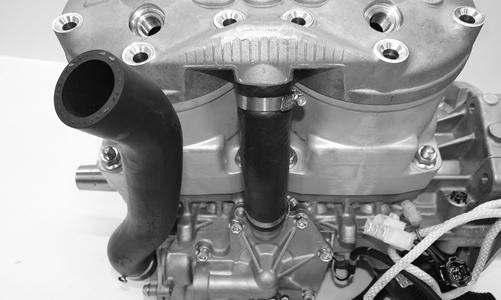
XM023
NOTE: At this time if the coolant temperature sensor was removed, install the sensor (threads coated with blue Loctite #243) and tighten to 18 ft-lb.
49. Apply a thin coat of high-temperature silicone sealant to each exhaust port; then install the exhaust gaskets. 50. Apply a thin coat of High-Temp Sealant to the mating surfaces of the exhaust manifold; then install the exhaust manifold and secure with the eight nuts.
Tighten the nuts using the pattern shown to 17 ft-lb.
Problem: Engine Does Not Start (No Spark at Spark Plugs) Condition Remedy 1. Key in the OFF position 1.Turn key to the ON position 2. Emergency stop switch in DOWN position — 2.Move switch to UP position — replace throttle control malfunctioning 3. Ground connections dirty — loose 3.Check all ground connections — clean and tight 4. RPS switch malfunctioning 4.Fully seat cable in control housing — Adjust throttle cable tension — replace faulty switch 5. Wiring harness shorting — disconnected 5.Repair — replace — connect wiring harness 6. Spark plugs fouled — damaged 6.Clean — replace spark plugs 7. Spark-plug caps damaged — leaking — shorting 7.Replace spark-plug caps 8. High tension leads/coil loose — grounded — faulty 8.Service — replace high tension leads/coil 9. Ignition timing sensor faulty 9.Replace sensor 10. Stator faulty 10.Replace stator 11. ECM/CCU faulty 11.Replace ECM/CCU Problem: Engine Does Not Start (No Fuel at Cylinders) Condition Remedy 1. Fuel tank empty 1.Fill tank 2. Fuel hose broken — pinched 2.Replace hose 3. Fuel tank vent hose — obstructed 3.Remove obstruction — replace vent — hose 4. Pick-up valve(s) obstructed — damaged 4.Remove obstruction — replace pick-up valve(s) 5. Fuel pressure regulator faulty 5.Replace regulator — hose 6. Fuel filter plugged 6.Replace fuel filter 7. Fuel pump faulty 7.Service — replace fuel pump — connections — wires 8. Wiring harness shorting — disconnected 8.Repair — replace — connect wiring harness 9. Injector (s) stuck closed 9.Replace injector(s) 10. Primary compression low 10.Repair — replace damaged — worn engine components 11. Stator faulty (Fuel pump or injector coil) 11.Replace stator 12. ECM faulty 12.Replace ECM Problem: Engine Does Not Start (Fuel Does Not Ignite) Condition Remedy 1. ECM/CCU trouble code 1.Service — replace problem component 2. Spark absent 2.Check for spark — see No Spark at Spark Plugs sub-section 3. Fuel contaminated 3.Replace gasoline 4. Primary compression low 4.Service engine 5. Secondary compression low 5.Service engine 6. Engine flooded 6.Clear engine (hold throttle full-open) 7. Sensor(s) faulty 7.Repair — replace problem sensor Problem: Engine Does Not Idle Condition Remedy 1. ECM/CCU trouble code 1.Service — replace problem component 2. Throttle position sensor idle adjustments incorrect 2.Adjust idle RPM to specifications 3. ISC faulty 3.Replace ISC 4. Reed petals chipped or broken 4.Replace reed petals 5. Injector(s) faulty 5.Replace injector(s) 6. Fuel pressure regulator faulty 6.Replace regulator 7. Air-intake silencer obstructed 7. Clean air-intake silencer 8. Exhaust obstructed 8.Remove obstruction 9. Primary compression low 9.Service Engine 10. Secondary compression low 10.Service Engine
Problem: Engine Loses Power or Runs on One Cylinder Condition Remedy 1. Sensor faulty 1.Check ECM for trouble code — repair — replace sensor 2. Spark plug fouled 2.Replace spark plugs 3. Injector faulty 3.Replace injector 4. External coil faulty 4.Service — replace coil 5. Fuel tank vent — hose obstructed 5.Service — replace vent hose 6. APV faulty 6.Inspect Cables — set cable tension — clean valves 7. Fuel pressure regulator faulty 7.Replace regulator 8. Pick-up valve(s) obstructed — out of position 8.Replace — relocate pick-up valve(s) 9. Secondary compression low 9.Service engine 10. Oil-injection pump malfunctioning — adjust incorrectly 10.Replace — bleed —adjust oil-injection pump 11. Throttle bodies out of synchronization 11.Replace throttle bodies from a similar engine — if problem is corrected, replace the original assembly
Problem: Engine Backfires Condition Remedy 1. ECM/CCU trouble code 1. Service — replace problem component 2. RPS switch adjusted incorrectly 2. Adjust throttle cable tension — service spring 3. Spark-plug caps damaged — leaking — shorting 3. Replace spark-plug caps 4. Spark plugs fouled - damaged 4. Clean — replace spark plugs 5. High tension leads/coil shorting or reversed 5. Service — replace high tension leads/coil 6. Coil Primary wires reversed 6. Reverse wires 7. Fuel mixture lean 7. Repair fuel regulator — injector(s) 8. Ignition Timing Sensor(s) faulty 8. Check Wiring-Replace sensor(s) 9. Oil-injection pump malfunctioning — adjusted incorrectly 9. Replace — bleed — adjust oil-injection pump 10. Reed petals chipped or broken 10. Replace reed petals 11. Engine overheated 11. Refill coolant — repair Thermostat — repair Water Pump Assembly 12. Knock Control system 12. Replace fuel with higher octane 13. ECM/CCU faulty — damaged 13. Replace ECM/CCU Problem: Engine Four-Cycles (Floods Excessively) Condition Remedy 1. ECM trouble code 1. Service — replace problem component 2. Fuel pressure too high 2. Replace regulator — hose 3. Fuel tank vent — hose obstructed 3. Service — replace vent hose 4. Injector(s) faulty 4. Replace injector(s) 5. Sensor(s) faulty 5. Repair — replace problem sensor(s) 6. Reed petals chipped or broken 6. Replace reed petals 7. Air silencer obstructed 7. Remove obstruction Problem: Engine Stops Suddenly Condition Remedy 1. Fuel tank empty 1. Fill tank 2. Emergency stop switch in DOWN position 2. Move switch to UP position 3. ECM/CCU trouble code 3. Service — replace problem component 4. Spark absent 4. See No Spark at Spark Plugs sub-section 5. Stator faulty 5. Replace stator 6. Wiring harness shorting — disconnected 6. Repair — replace — connect wiring harness 7. Fuel filter(s) obstructed 7. Replace filter(s) 8. Fuel pressure low 8. Replace regulator — hose 9. Fuel pump faulty 9. Service — replace fuel pump 10. Fuel tank vent hose obstructed 10. Service vent hose 11. Fuel hose obstructed — broken — pinched 11. Remove obstruction — repair — replace fuel hose 12. RPS switch malfunctioning 12. Replace throttle control — adjust throttle cable tension 13. Engine seized 13. Service engine 14. ECM/CCU faulty 14. Replace ECM/CCU Problem: Engine Fails to Stop (Continues to Run, Even with All Switches Off) Condition Remedy 1. ECM internal 1. Replace ECM 2. Wiring harness disconnected — faulty harness 2. Repair — replace — connect wiring harness 3. Key switch faulty 3. Replace key switch 4. Emergency stop switch faulty 4. Replace E-stop control housing