Drive System NOTE: Some photographs and illustrations used in this section are used for clarity purposes only and are not designed to depict actual conditions.
Drive Chain/Sprockets MD2357
CHECKING DRIVE CHAIN AND SPROCKETS
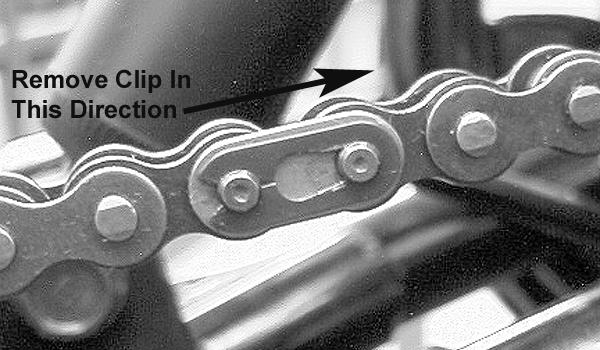
2. Remove the link plate and link noting the position of the O-rings; then remove the chain.
The following drive system components should be inspected periodically to ensure proper operation. A. Chain (excessive stretch or slack). B. Sprockets (excessive wear/hooking, missing or broken teeth).
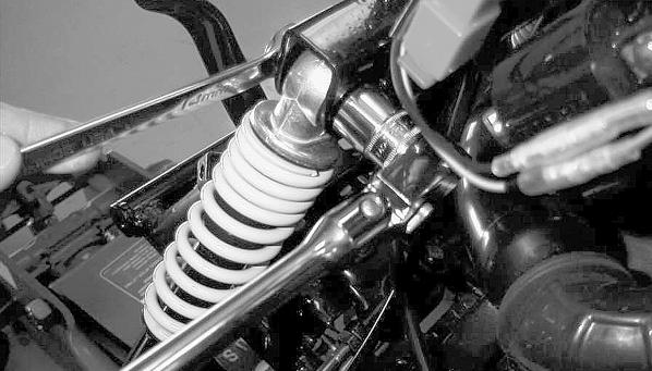
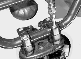
ADJUSTING DRIVE CHAIN 1. Loosen the four cap screws (A) securing the rear axle housing to the rear swing arm.
KM238A
INSTALLING DRIVE CHAIN 1. Place the drive chain into position on the sprockets. 2. Making sure to place the O-rings into position, install the master link, link plate, and link clip.
KM831A
2. Tighten the adjuster nut (B) on the adjusting bolt until approximately 30 mm (1.18 in.) of slack is present at mid-span of the chain.
KM238A
NOTE: Make sure the closed end of the master link clip faces the direction of the rotation of the chain.
KM218A
3. Tighten the four cap screws.
REMOVING DRIVE CHAIN 1. Remove the drive chain master link clip.
67