9 minute read
Steering/Frame/Controls

The following steering components should be inspected periodically to ensure safe and proper operation.
A.Handlebar grips worn, broken, or loose.
B.Handlebar bent, cracked, and an equal and complete full-left and full-right turn capability.
C.Steering post bearing assembly/bearing housing broken, worn, or binding.
D.Ball joints worn, cracked, or damaged.
E.Tie rods bent or cracked.
F. Knuckles worn, cracked, or damaged.
G.Cotter pins damaged or missing. The frame and welds should be checked periodically for damage, bends, cracks, deterioration, broken components, and missing components.
Steering Post/Handlebar/ Tie Rods
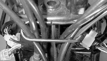
REMOVING 1. Remove the seat. 2. Remove the control cables from the handlebar; then route them through the metal loop on the steering post and out of the way.

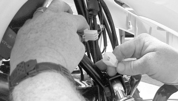
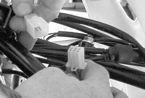
MD2430 MD2139 4. Disconnect the handlebar switch assembly and brake switch connectors; then route them through the metal loop on the steering post and out of the way.

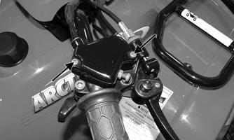
MD2416 5. Remove the cap screws securing the body panel. On the Utility, remove the front and rear racks. 6. Remove the gas tank cap and lift off the panel.
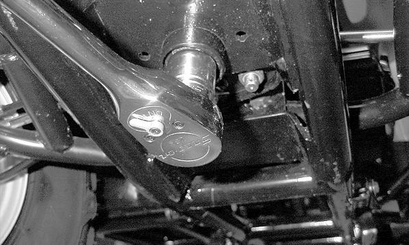
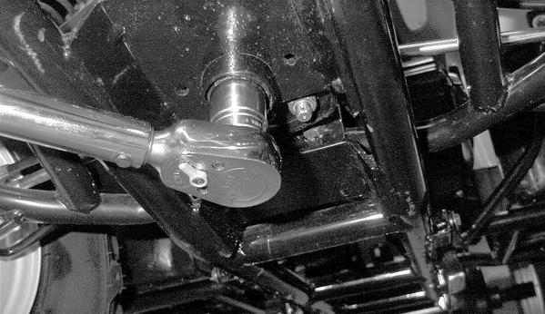
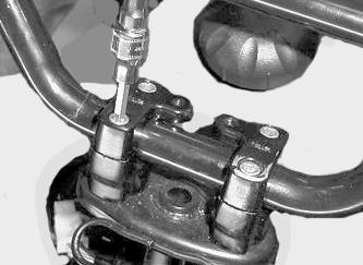
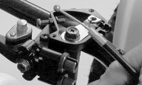
MD2405 7. Remove the cotter pins; then remove the two inner tie rod ends from the steering post.
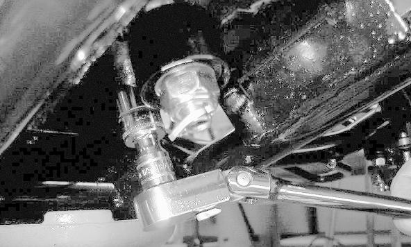
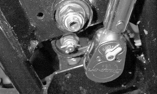
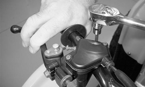
MD2136 8. Remove the cotter pin; then remove the steering post nut.
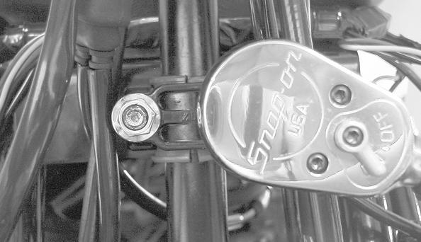
MD2417 9. Remove the steering post outer bearing cap and remove the steering post assembly. Account for the two nuts, the outer bearing cap, and the two-piece plastic bearing. NOTE: The inner bearing cap and the two spacers do not need to be removed.

MD2142
CLEANING AND INSPECTING 1. Wash the tie rod ends in parts-cleaning solvent. Dry with compressed air. Inspect the pivot area for wear.
Apply a low-temperature grease to the ends.
2. Inspect the tie rods for damaged threads or wear. 3. Inspect the tie rods for cracks or unusual bends. 4. Inspect all welded areas for cracks or deterioration. 5. Inspect the steering post and brackets for cracks, bends, or wear. 6. Inspect the plastic bearing halves and bearing caps for cracks or wear. 7. Inspect the handlebar tube for cracks, wear, or unusual bends. INSTALLING 1. Place the steering post into position. Tighten the two nuts on the outer bearing cap making sure the two-piece plastic bearing is in place. Tighten the nuts to 20 ft-lb.
! WARNING
Always wear safety glasses when using compressed air.
MD2432 2. Install the steering post nut and tighten to 51 ft-lb.
Install a new cotter pin.
MD2418 3. Install the inner tie rod ends. Tighten the nuts to 20 ft-lb and install new cotter pins.
MD2419 4. Route the control cables and wiring through the metal loop on the steering post.
MD2135
5. Install the body panel and gas tank cap.
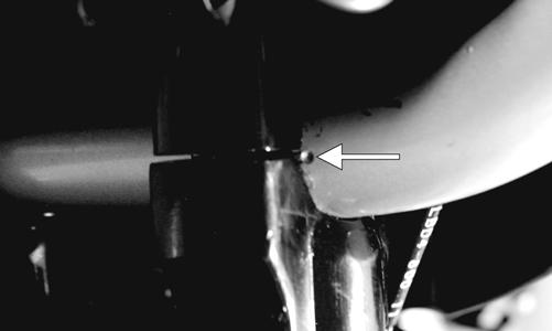
MD2405 6. Install handlebar with marks aligned with the handlebar mounting clamps. Install the caps; then tighten the cap screws to 10 ft-lb.
KM060A
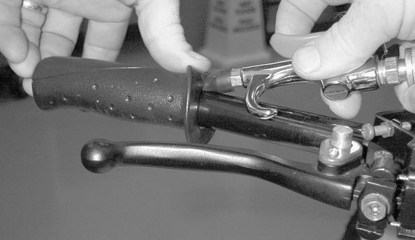
7. Install the control cables onto the handlebar.
MD2429 MD2439 8. Make sure the cables (brake and throttle) are routed down and away so there is no sticking or binding. ! WARNING
Make sure there is maximum right/left steering capability and the brake and throttle cables are not affected.
MD2105
MD2441
MD2434
MD2445
10. Install the seat. 11. On the Utility, install the front and rear racks.
Handlebar Grip
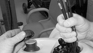
REMOVING 1. Using a compressed air nozzle and low pressure, peel up the inner corner of the grip. 2. Apply air pressure while twisting the grip back and forth until it slides off the handlebar.
MD2448
INSPECTING 1. Inspect the grip for wear, cuts, or cracks. 2. Inspect the grip for deterioration.
NOTE: Before installing a handlebar grip, use contact spray or alcohol to clean the inside of the grip and the handlebar of glue residue, oil, or any other contaminant.
1. Apply a liberal amount of Handlebar Grip Adhesive to the inside of the grip. 2. Slide the grip onto the handlebar until it is fully seated. 3. Wipe off any excess adhesive.
Handlebar Switch
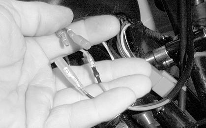
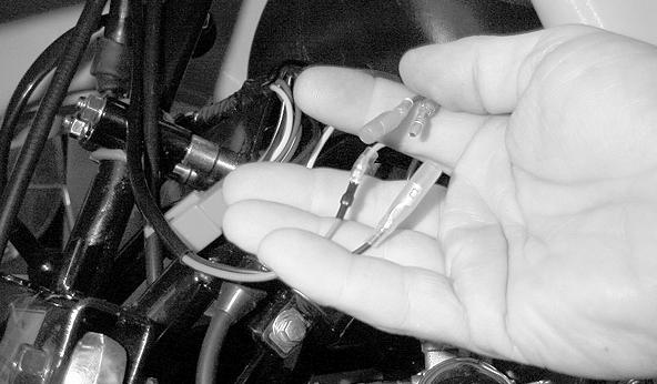
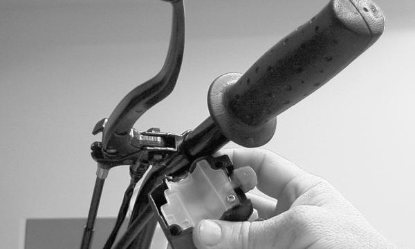
REMOVING 1. Disconnect the handlebar switch assembly wiring connector.

MD2434 2. Disconnect the brake switch wiring connectors.
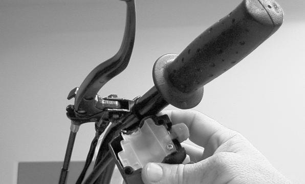
MD2438 3. Remove the handlebar switch assembly from the handlebar.
KM544
MD2436
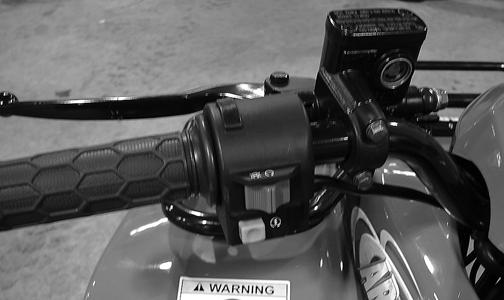
INSTALLING 1. Place the handlebar switch assembly onto the handlebar. Tighten the screw securely.
MD2436
KM544
2. Connect the brake switch wiring connectors.

MD2438 3. Connect the handlebar switch assembly wiring connector.
MD2434
Hand Brake Lever Assemblies
! WARNING
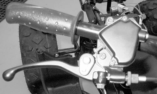
After removing and installing brake-related components, ALWAYS check and adjust brakes as necessary before operating the ATV. REMOVING 1. Remove the right handlebar grip. 2. Remove the cover from the throttle control housing exposing the throttle cable; then remove the cable.

MD2440
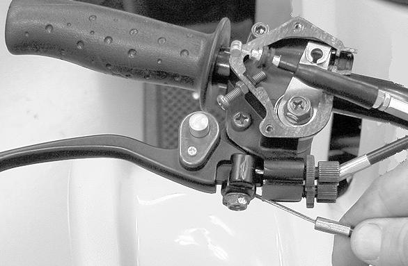
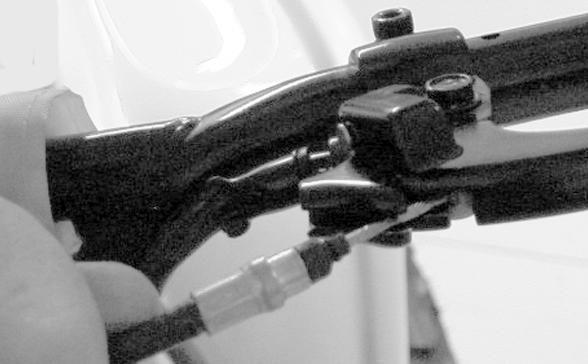
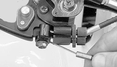
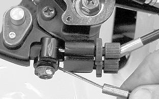
MD2439 3. Remove the front brake cables from their adjusters by screwing the adjusters inward to loosen the cables; then pulling them free.
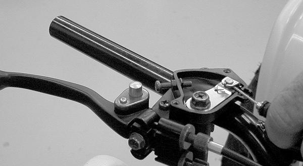
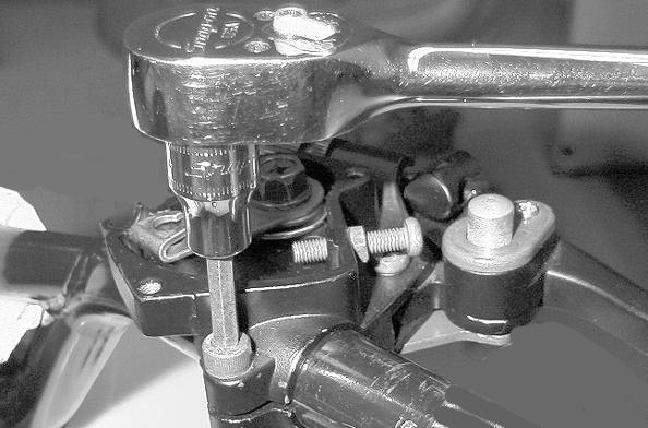
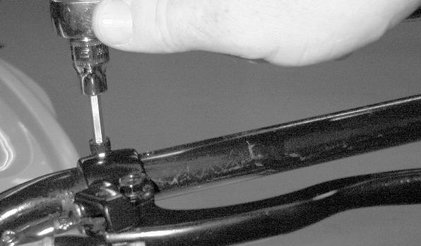
MD2449 4. Loosen the 6 mm Allen-head screw securing the front brake lever assembly and slide the assembly off the handlebar.
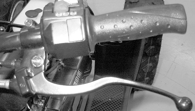
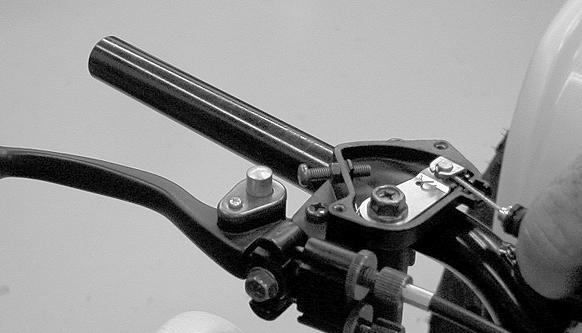
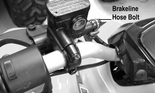
MD2450 5. Place a suitable container beneath the left-hand brake master cylinder. 6. Remove the brakeline hose bolt; then drain brake fluid into the container. Account for two copper washers.
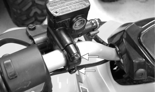
KM208B 7. Remove the cap screws securing the hand brake lever assembly to the handlebar and remove the hand brake/master cylinder assembly.
KM208A
MD2442
INSTALLING 1. Slide the right brake lever assembly onto the handlebar; do not tighten the Allen-head screw completely at this time.
MD2452 2. Install the throttle cable into the throttle control housing; then install the cover and secure with the screws.
MD2454
KM548A
3. Install the brake cable to the lever assembly.
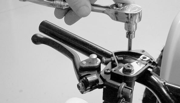
MD2453 4. Position the left brake lever assembly onto the handlebar and secure with the clamp and two cap screws. Tighten securely.
KM208A 5. Install the brakeline hose on the master cylinder with the brakeline hose bolt and two washers. Do not tighten the bolt at this time.
KM208B 6. Remove the cover from the master cylinder and fill with DOT 4 brake fluid; then install the cover. 7. Place a suitable container under the master cylinder and compress the lever slowly. Brake fluid should flow from the loose connection. 8. Tighten the brakeline hose bolt to 20 ft-lb (from step 5); then check the rear brake operation. The brake lever should be firm and the rear brake should stop the wheels.
NOTE: If the brake is not firm, the system must be bled (see Brake Systems - BLEEDING in Periodic Maintenance/Tune-Up section). NOTE: Before installing a handlebar grip, use contact spray or alcohol to clean the inside of the grip and the handlebar of adhesive residue, oil, or any other contaminant.
9. Apply a liberal amount of Handlebar Grip Adhesive to the inside of the grip; then slide the right grip onto the handlebar. Wipe off any excess adhesive. 10. Tighten the right brake lever assembly Allen-head screw (from step 1) securely.
MD2461
Troubleshooting
Problem: Handling too heavy or stiff Condition Remedy 1. Front wheel alignment incorrect 1.Adjust alignment 2. Lubrication inadequate 2.Lubricate appropriate components 3. Tire inflation pressure incorrect 3.Adjust pressure 4. Tie rod ends seizing 4.Replace tie rod ends 5. Linkage connections seizing 5.Repair - replace connections Problem: Steering oscillation Condition Remedy
1. Tires inflated unequally 2. Wheel(s) wobbly 3. Wheel hub cap screw(s) loose - missing 4. Wheel hub bearing worn - damaged 5. Tie rod ends worn - loose 6. Tires defective - incorrect 7. A-arm bushings damaged 8. Bolts - nuts (frame) loose 1.Adjust pressure 2.Replace wheel(s) 3.Tighten - replace cap screws 4.Replace bearing 5.Replace - tighten tie rod ends 6.Replace tires 7.Replace bushings 8.Tighten bolts - nuts
Problem: Steering pulling to one side Condition Remedy 1. Tires inflated unequally 1.Adjust pressure 2. Front wheel alignment incorrect 2.Adjust alignment 3. Wheel hub bearings worn - broken 3.Replace bearings 4. Frame distorted 4.Repair - replace frame 5. Shock absorber defective 5.Replace shock absorber Problem: Steering impaired Condition Remedy 1. Tire pressure too high 1.Adjust pressure 2. Steering linkage connections worn 2.Replace connections 3. Cap screws (suspension system) loose 3.Tighten cap screws Problem: Tire wear rapid or uneven Condition Remedy 1. Wheel hub bearings worn - loose 1.Replace bearings 2. Front wheel alignment incorrect 2.Adjust alignment Problem: Steering noise Condition Remedy 1. Caps screws - nuts loose 1.Tighten cap screws - nuts 2. Wheel hub bearings broken - damaged 2.Replace bearings 3. Lubrication inadequate 3.Lubricate appropriate components