11 minute read
Suspension

The following suspension system components should be inspected periodically to ensure proper operation.
A.Shock absorber rods bent, pitted, or damaged.
B.Rubber damper cracked, broken, or missing.
C.Shock absorber body damaged, punctured, or leaking.
D.Shock absorber eyelets broken, bent, or cracked.
E.Shock absorber eyelet bushings worn, deteriorated, cracked, or missing.
F. Shock absorber spring broken or sagging.
Shock Absorbers
REMOVING FRONT SHOCK ABSORBERS 1. Secure the ATV on a support stand to elevate the wheels and to release the load on the suspension. ! WARNING
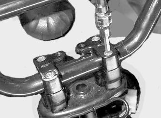
Make sure the ATV is solidly supported on the support stand to avoid injury. 2. Remove the cap screw and self-locking nut securing each front shock absorber to the frame.
MD2131 3. Remove the cap screw and self-locking nut securing each front shock to the A-arms. 4. Remove the front shock absorbers. REMOVING REAR SHOCK ABSORBER 1. Secure the ATV on a support stand to elevate the wheels and to release the load on the suspension.
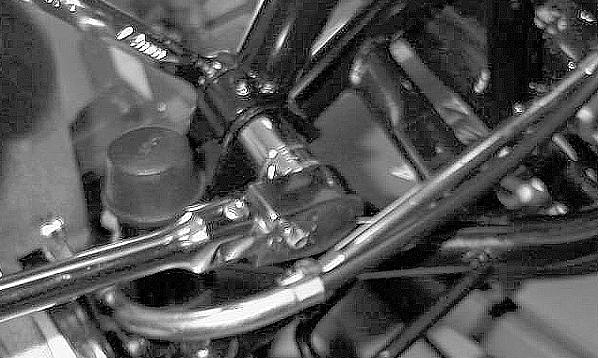
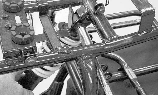
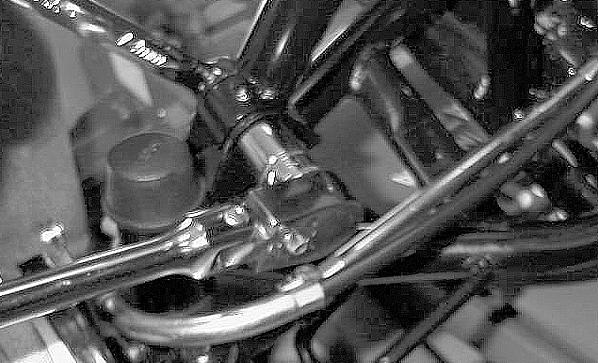
2. Remove the cap screw securing the rear shock absorber to the frame.
! WARNING
Make sure the ATV is solidly supported on the support stand to avoid injury. CAUTION
Additional support stands are necessary to support the rear axle when the shock absorbers are removed or damage may occur.
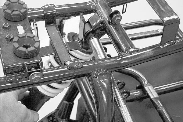
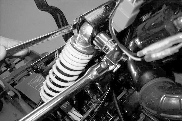
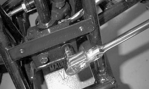
MD2314 3. Remove the cap screw securing the rear shock absorber to the swing arm; then remove the rear shock absorber.
MD2315 4. Compress the shock absorber spring and remove the spring retainer. Remove the spring and spring preload adjuster. CLEANING AND INSPECTING 1. Clean all shock absorber components. 2. Inspect each shock rod for nicks, pits, rust, bends, and oily residue. 3. Inspect all springs, spring retainers, shock rods, dampers, bushings, shock bodies, and eyelets for cracks, leaks, and bends.
INSTALLING FRONT SHOCK ABSORBERS 1. Place a shock absorber into position on the frame and
A-arm and install the two cap screws and self-locking nuts. Tighten the nuts to 29 ft-lb.
MD2131 MD2314
MD2132 2. Repeat the procedure for the other front shock absorber.
3. Remove the ATV from the support stand. INSTALLING REAR SHOCK ABSORBER 1. Place the spring preload adjuster and spring over the shock absorber. Compress the spring and install the retainer. 2. Place the shock absorber into position on the frame and swing arm and install the two cap screws.
Tighten the cap screws to 29 ft-lb.
CAUTION
Do not tighten the nuts beyond the 29 ft-lb specification or the shock eyelet or mount WILL be damaged.
MD2315
CAUTION
Do not tighten the cap screws beyond the 29 ft-lb specification or the shock eyelet or mount WILL be damaged. 3. Remove the ATV from the support stand.
A-Arm
REMOVING 1. Secure the ATV on a support stand to elevate the front wheel; then remove the wheel.
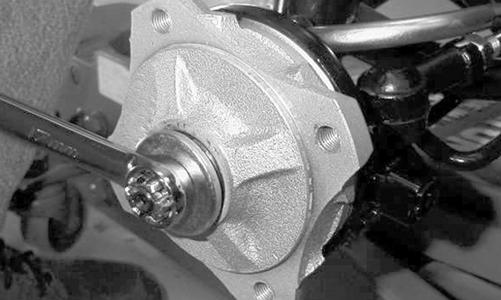
2. Remove the cotter pin, castle nut, and washer; then remove the hub assembly.
! WARNING
Make sure the ATV is solidly supported on the support stand to avoid injury.
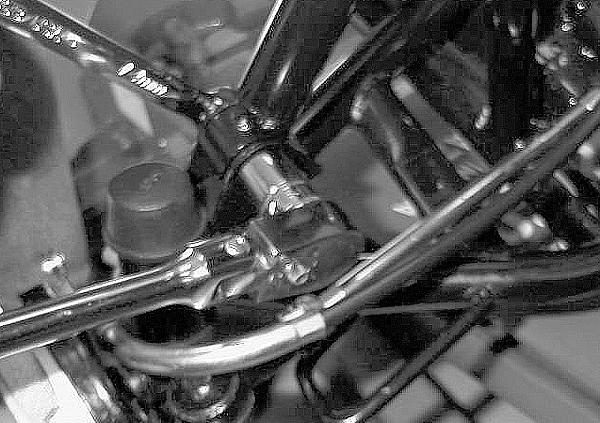
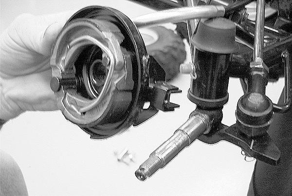
3. Slide brake backing plate assembly off the spindle shaft and secure it out of the way. 4. Remove the cotter pin from the outer tie rod end; then while holding the flat on the tie rod end, remove the castle nut.
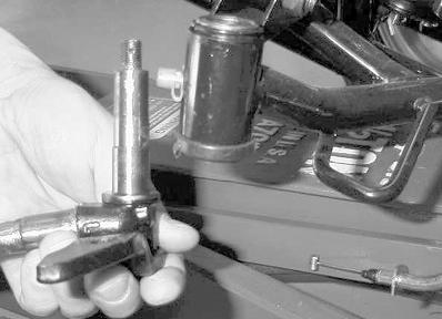
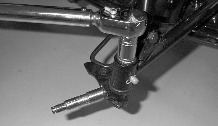
MD2428 5. Remove the tie rod end from the steering knuckle. 6. Remove the rubber spindle pin boot; then remove the cotter pin and flanged castle nut from the spindle pin.
Lower the steering knuckle assembly from the Aarm.
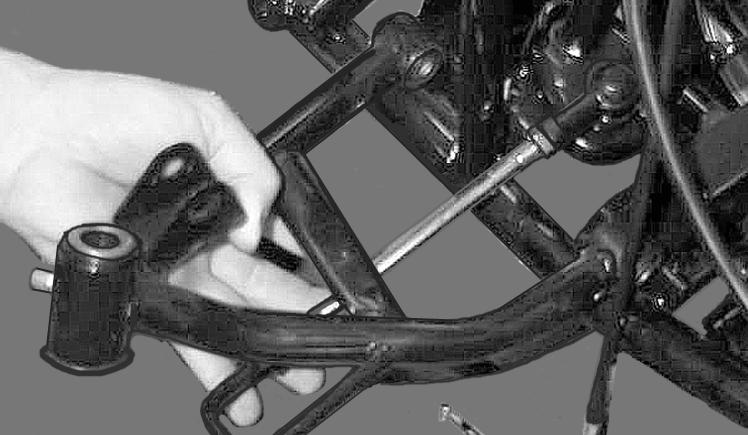
MD2113 7. Remove the cap screw and self-locking nut securing the shock absorber to the A-arm.
MD2132 8. Remove the cap screws and self-locking nuts securing the A-arm to the frame.
MD2121
9. Remove the A-arm.
MD2119
CLEANING AND INSPECTING 1. Clean all A-arm components in parts-cleaning solvent. 2. Clean the tie rod mounting hole of all residual Loctite, grease, oil, or dirt for installing purposes. 3. Inspect the A-arm for bends, cracks, and worn bushings. 4. Inspect the tie rod mounting holes for cracks or damage. 5. Inspect the frame mounts for signs of damage or wear. INSTALLING NOTE: During installing, new cotter pins should be installed.
1. Lubricate the A-arm bushings with grease; then install the A-arm into the frame. Install the cap screws and self-locking nuts. Tighten the nuts to 29 ft-lb.
CAUTION
Do not tighten the nut beyond the 29 ft-lb specification or the shock eyelet or mount WILL be damaged.
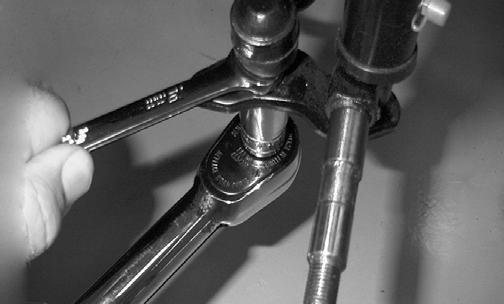
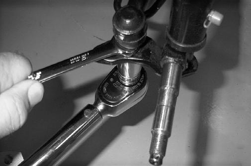
MD2424 3. Lubricate the steering knuckle assembly with grease; then install it into the A-arm and secure with the flanged castle nut. Tighten the nut to 29 ft-lb; then install a new cotter pin and the rubber spindle pin boot.
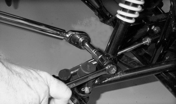
MD2427 4. Install the tie rod end into the steering knuckle and secure it with the self-locking nut. Tighten the nut to 25 ft-lb; then install a new cotter pin.
MD2426 5. Apply a light coat of grease to spindle shaft; then install the brake backing plate assembly onto the shaft. NOTE: When installing the brake backing plate assembly, be sure to align the notch in the backing plate with the tab on the steering knuckle.
MD2381 6. Place the hub assembly onto the spindle; then install the washer and castle nut. Tighten the castle nut to 45 ft-lb; then install a new cotter pin. Install the wheel and tighten the cap screws to 30 ft-lb. 7. Remove the ATV from the support stand. ! WARNING
After removing and installing brake-related components, ALWAYS check and adjust brakes as necessary before operating the ATV.
Swing Arm
REMOVING 1. Secure the ATV on a support stand to elevate the rear wheels; then remove the wheels.
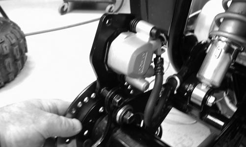
2. Remove two cap screws securing the brake caliper to the axle housing.
! WARNING
Make sure the ATV is solidly supported on the support stand to avoid injury.
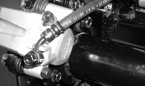
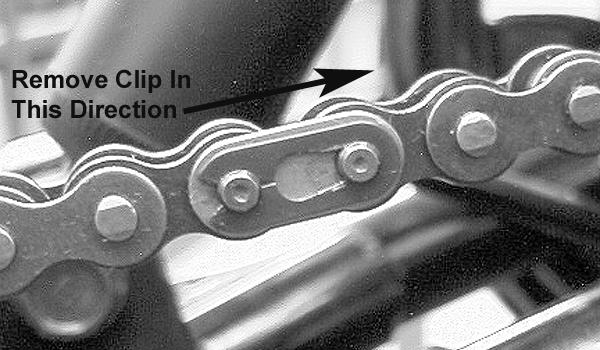
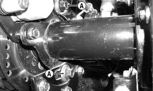
KM207 3. Remove drive chain, hubs, spacers, and axle as necessary (see the Drive System section). NOTE: Do not remove more components than necessary to perform the intended service. The axle housing will separate from the swing arm with all components attached if necessary. 4. Remove the four cap screws (A) securing the axle housing to the swing arm; then remove the axle housing.
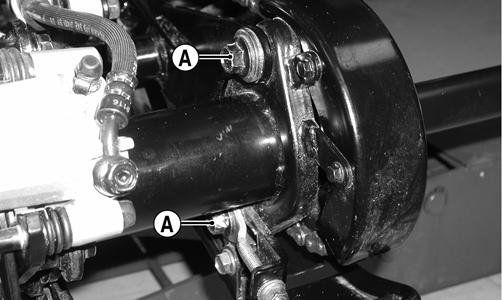
KM217B
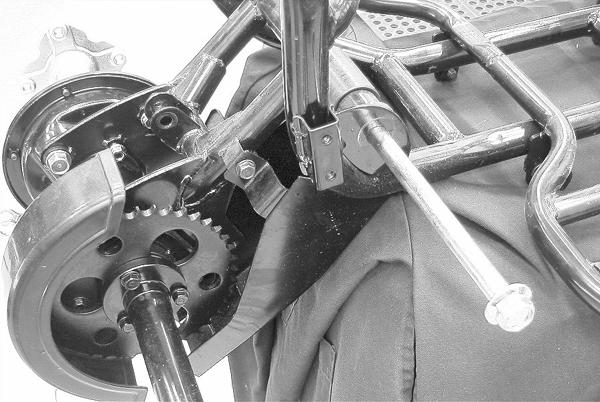
KM212A 5. Remove the cap screws securing the skid plate and rear chain guard; then remove the skid plate and rear chain guard.
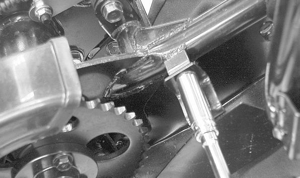
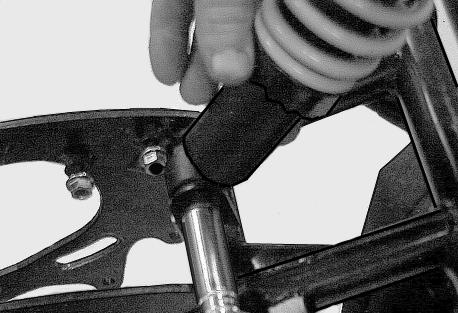
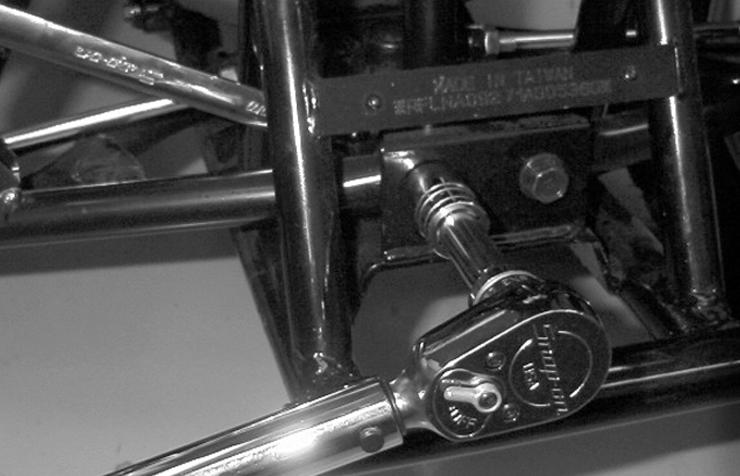
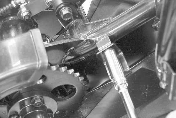
MD2014 6. Remove the cap screw securing the shock absorber to the swing arm. 7. Remove the long cap screw and self-locking nut securing the front of the swing arm to the frame brackets; then remove the swing arm from the frame.
Account for two seals, a spacer, a rubber swing arm guard, and a washer.
MD2007
MD2312
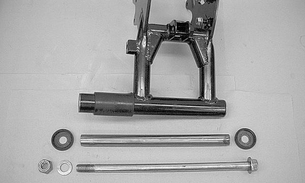
CLEANING AND INSPECTING 1. Clean all swing arm components in parts-cleaning solvent. 2. Inspect all swing arm welds for cracks or unusual bends. 3. Inspect all tubing for cracks or unusual bends. 4. Inspect the pressed-in bushings for damage. 5. Inspect the rubber swing arm guard for damage. 6. Inspect the seals for damage. INSTALLING 1. Lubricate the pressed-in swing arm bushings with a light coat of grease; then install the spacer into the swing arm. 2. If removed, install the rubber swing arm guard. 3. Lubricate the two seals with a light coat of grease; then install them on the ends of the swing arm. 4. Position the swing arm in the frame and slide the long cap screw through the brackets and swing arm.
MD2315
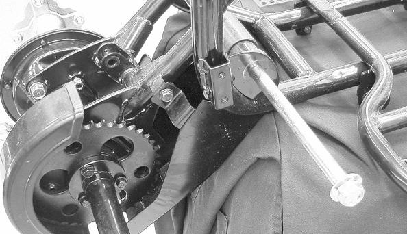
MD2007 5. Install the washer and self-locking nut. Tighten the nut to 50 ft-lb. 6. Install the axle, spacers, hubs, and drive chain (see the Drive System section). 7. Secure the shock absorber to the swing arm with the cap screw. Tighten the cap screw to 29 ft-lb.
MD2315
CAUTION
Do not tighten the cap screw beyond the 29 ft-lb specification or the shock eyelet or mount WILL be damaged. 8. Place the rear chain guard and skid plate into position and install the cap screws; then tighten the cap screws securely.
MD2014 9. Place the axle housing into position on the swing arm; then install and tighten four cap screws to 29 ft-lb. 10. Install the brake caliper on the axle housing with the two cap screws. Tighten securely.
KM229 11. Install the wheels and tighten the cap screws to 30 ftlb; then remove the ATV from the support stand. ! WARNING
After removing and installing of brake-related components, ALWAYS check and adjust brakes as necessary before operating the ATV.
Wheels and Tires
TIRE SIZE
! WARNING
Use only Arctic Cat approved tires when replacing tires. Failure to do so could result in unstable ATV operation. The ATV is equipped with low-pressure tubeless tires of the size and type listed (see General Information - General Specifications). Do not under any circumstances substitute tires of a different type or size.
! WARNING
Do not mix tire tread patterns. Use the same pattern type on front and rear. Failure to heed warning could cause poor handling qualities of the ATV and could cause excessive drive train damage not covered by warranty.
TIRE INFLATION PRESSURE Front and rear tire inflation pressure should be 0.21 kgcm2 (3.0 psi).
! WARNING
Always maintain proper tire inflation pressure. REMOVING 1. Secure the ATV on a support stand to elevate the wheels.
2. Remove the four cap screws securing each wheel; then remove the wheels.
! WARNING
Make sure the ATV is solidly supported on the support stand to avoid injury.
CLEANING AND INSPECTING 1. Clean the wheels and hubs with parts-cleaning solvent. 2. Clean the tires with soap and water. 3. Inspect each wheel for cracks, dents, or bends. 4. Inspect each tire for cuts, wear, missing lugs, and leaks. INSTALLING 1. Install each wheel on its hub.
NOTE: Make sure each wheel is installed on its proper hub as noted in removing (the “rotation arrow” must indicate forward direction of rotation). 2. Tighten cap screws to 30 ft-lb. CHECKING/INFLATING 1. Using an air pressure gauge, measure the air pressure in each tire. Adjust the air pressure as necessary to meet the specified inflation pressure. 2. Inspect the tires for damage, wear, or punctures. ! WARNING
Do not operate the ATV if tire damage exists. NOTE: If repair is needed, follow the instructions found on the tire repair kit or remove the wheel and have it repaired professionally. NOTE: Be sure all tires are the specified size and have identical tread pattern. 3. Test drive the ATV on a dry, level surface and note any pulling to the left or right during acceleration, deceleration, and braking. NOTE: If pulling is noted, measure the circumference of the front and rear tires on the pulling side. Compare the measurements with the tires on the opposite side. If pulling is noted during braking only, check and adjust the brakes as necessary and recheck operation (see the Periodic Maintenance/ Tune-Up section). 4. Increase the air pressure in the tires with the smallest circumference measurement until all tires are equal in circumference. 5. Repeat steps 3-4 as necessary to ensure proper handling.
Troubleshooting
Problem: Suspension too soft Condition Remedy 1. Spring(s) weak 1.Replace spring(s) 2. Shock absorber damaged 2.Replace shock absorber Problem: Suspension too stiff Condition Remedy 1. A-arm bushings worn 1.Replace bushing 2. Shock absorber improperly adjusted (rear) 2.Adjust shock spring preload Problem: Suspension noisy Condition Remedy 1. Cap screws (suspension system) loose 1.Tighten cap screws 2. A-arm bushings worn 2.Replace bushings Problem: Rear wheel oscillation Condition Remedy 1. Rear wheel hub bearings worn - loose 1.Replace bearings 2. Tires defective - incorrect 2.Replace tires 3. Wheel rim distorted 3.Replace wheel 4. Wheel hub cap screws loose 4.Tighten cap screws 5. Axle shaft nut loose 5.Tighten nut 6. Rear brake adjusted incorrectly 6.Adjust brake 7. Rear suspension arm-related bushing worn 7.Replace bushing 8. Rear shock absorber damaged 8.Replace shock absorber 9. Rear suspension arm nut loose 9.Tighten nut
Printed in U.S.A. Trademarks of Arctic Cat Inc., Thief River Falls, MN 56701 p/n 2259-817