
6 minute read
Exhaust system, emission control


DME engine electronics 2


2_457_11
2.10 Exhaust system, emission control
All exhaust system variants feature flow-optimized exhaust manifolds with catalytic converters arranged close to the engine (see Fig. 2_457_11, 1) as well as a common front muffler (see Fig. 2_456_11, 2) and one main muffler (3) per cylinder bank with corrugated tube (4).
The purpose of the corrugated tube on the main muffler is to improve vibration comfort during idling.
The specifications for the exhaust systems are described on the following pages. The following are installed worldwide for all engines: • Identical flow-optimized exhaust manifold/catalytic converter modules • 5 different front mufflers • 3 different main mufflers • 3 different tailpipe covers
2_458_11
Caution when handling: Do not pick up the main muffler by the short tube end! Risk of deforming the corrugated tube (4).
2_456_11
Standard exhaust system for the 3.4-liter engine
The 3.4-liter engine features a twin-branch exhaust system with catalytic converters arranged close to the engine (1) on the flow-optimized exhaust manifold, a common front muffler (2), two main mufflers (3) and individual tailpipe covers (4) as standard.
The main mufflers (3) have an intake pipe and exhaust pipe with a diameter of 55 mm.
The exhaust system has been derestricted by optimizing flow characteristics in order to reduce exhaust backpressure.


2_459_11 DME engine electronics 2

2_461_11
Twin-branch exhaust system 1 Catalytic converters arranged close to the engine on the exhaust manifold 2 One common front muffler 3 One main muffler per cylinder bank 4 Individual tailpipe covers

2_460_11
DME engine electronics 2

2_465_11

2_464_11
1 Catalytic converters arranged close to the engine on the exhaust manifold 2 Front muffler 3 With two exhaust flaps on the front muffler 4 One main muffler per cylinder bank 5 Twin tailpipe covers Exhaust system for the 3.8-liter engine
Layout of the 911 Carrera S flap exhaust system (standard on the S model)
The 3.8-liter Carrera S engine features a four-branch exhaust system with catalytic converters arranged close to the engine (1) on the flow-optimized exhaust manifold, a common front mufflers (2), two flap-controlled bypass pipes (3), two main mufflers (4) and two twin tailpipe covers (5).
The main mufflers (4) have an intake pipe with a diameter of 55 mm and an exhaust pipe with a diameter of 52 mm.
2_462_11
The map-controlled, electropneumatic flap control of the 911 Carrera S exhaust system increases the engine power by further reducing exhaust backpressure at increased rpm and engine load.

Exhaust flap switching (Carrera S)
The Carrera S exhaust system does not feature a switch for activating and deactivating the exhaust flaps.
The exhaust flaps are activated using a map in the DME control unit as a function of engine speed and load: • Engine speed: >3,300 rpm • Load: Slight, partial-load acceleration (corresponds to an air mass of 400 mg/stk)
In this case the DME control unit sends a CAN signal via the gateway to the rear-end electronics, which activate the electropneumatic switching valve.
A completely redesigned sports exhaust system is available for the 911 Carrera (991) models. The main innovation to the sports exhaust system is an extended functionality. For the first time, activating the sports exhaust system not only derestricts the exhaust gas routing but also enables the two exhaust tracts to be connected. This pairs an unmistakable flat-six engine sound with optimum performance. This results in more emotive acoustics.
For visual differentiation, the sports exhaust system has two twin tailpipes with a unique nozzle design and nano-coating.
Exhaust flap switching (sports exhaust system)
On the optional sports exhaust system, switching of the exhaust flaps to an acoustically optimized mode can only be activated or deactivated following a request using one of the following buttons: • Sport button • Sport Plus button • Sports exhaust system button (the sports exhaust system can also be deactivated using this button). The exhaust flaps are activated in accordance with the request using the map in the DME control unit, as on the Carrera S.
In this case the DME control unit sends a CAN signal to the gateway; it receives the corresponding button request via CAN from the operating and air conditioning unit. Only then does the gateway send a CAN signal to the rear-end electronics, which activate the electropneumatic switching valve. DME engine electronics 2
2_466_11
2_467_11
2_468_11
DME engine electronics 2

2_469_11

2_470_11
• Sporty sound and improved torque curve • Two twin tailpipes with a unique nozzle design • An acoustically optimized mode can be activated and deactivated by pressing a button • When the sports exhaust system is activated, the indicator light in the button lights up
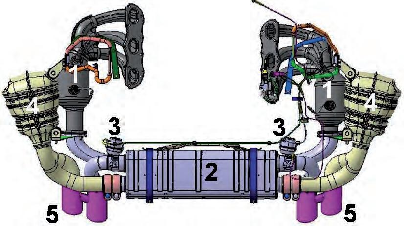
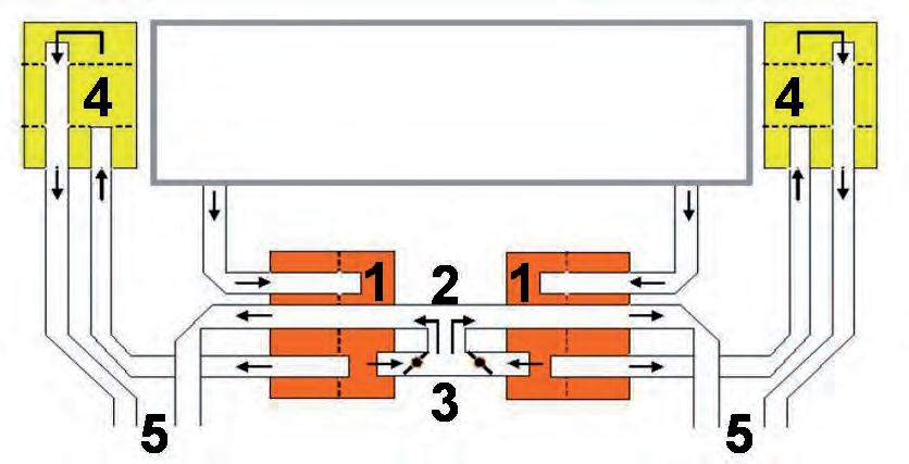
1 Front muffler with 2 Connection as well as 3 Two central exhaust flaps with modified positioning 4 One 52 mm main muffler per cylinder bank (50 mm in some cases) 5 Two twin tailpipes with a unique nozzle design
Layout of the sports exhaust system (available as an option for the 3.4-liter and 3.8-liter engines)
Four-branch sports exhaust system with catalytic converters arranged close to the engine on the flow-optimized exhaust manifold, a common front muffler (1) with central map-controlled, electropneumatically switchable exhaust flaps of the bypass pipes (3), two main mufflers (4) and two twin tailpipe covers (5) with unique nozzle design. The main mufflers (4) have an intake pipe with a diameter of 55 mm and, in some countries, an exhaust pipe with a diameter of 52 mm or 50 mm.
On the sports exhaust system, activating the exhaust flaps also reduces the exhaust back pressure (for a sporty sound and improved torque curve) as well as establishing a connection between banks 1 and 2. The connection results in resonance induction between the left and right cylinder banks.

2_471_11
2_472_11
There is one three-way main catalytic converter with ceramic monolith (1) per cylinder bank installed at the end of the flow-optimized exhaust manifold. The catalytic converter diameter is 125 mm, the length 120 mm, it has 400 cells and a wall thickness of 4.5 mm.
The oxygen sensor LSF downstream of the catalytic converter (3) is installed seven tenths of the way along the length of the main catalytic converter; this corresponds to 84 mm from the intake surface.
The funnel (4) upstream and downstream of the catalytic converter is air-gap insulated to reduce the emission levels.
Bank-specific oxygen sensor closed-loop control with: 1 Ceramic main catalytic converter (three-way), left + right 2 Broadband oxygen sensors (LSU) upstream of catalytic converter 3 Oxygen sensors (LSF) downstream of catalytic converter 4 Air-gap insulated funnel upstream and downstream of catalytic converter
The vehicles comply with the worldwide exhaust emission standards: EURO 4 (EOBD) EURO 5 (EOBD) USA LEV II (OBD II) DME engine electronics 2


