4 minute read
DME diagnosis


2.4 DME diagnosis
The DME control unit Continental SDI 9 can be programmed with the data records for the relevant emission standards, for example EURO 4 (EOBD), EURO 5 (EOBD), USA LEV II (OBD II), on a country-specific basis.
The DME control unit EMS SDI 9 provides the following new DME diagnostic functions and sequences on PIWIS Tester II, for example: • Actual values, for example for thermal management and Auto Start Stop system • System test for vacuum system • System test for thermostat • Bleeding the cooling system • New short tests (more user-friendly and with F1 –help)
Further DME diagnostic information can be found in PIWIS Tester II under: • F1 –help (context-sensitive help) • as well as in Guided Fault Finding/Components and functions/Drive/General information

Actual values
The following new function groups are available under the DME actual values: • T_Temperatures Actual values for thermal management. • ST_Start Stop Actual values for the Auto Start Stop system. • LV_Short test results If the ignition was not switched off after performing a test drive (the vehicle is still running), you can see which short tests have already been carried out for this driving cycle under the DME actual values “LV_Short test results”.
In this case, it is sufficient to carry out the outstanding short tests in order to achieve the Ready status for all OBD-relevant systems. Only once all systems have achieved the Ready status can it be established whether these are OK by checking the fault memory. DME engine electronics 2

DME engine electronics 2

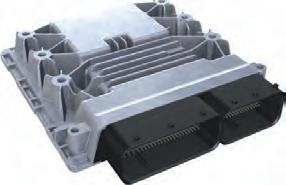
2_408_11

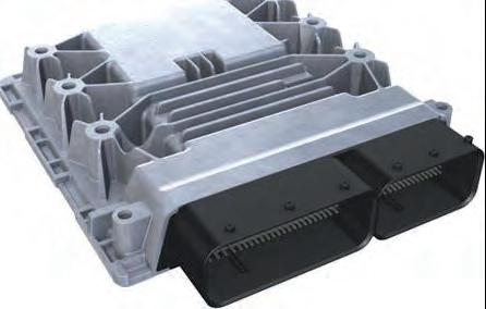
2_407_11 Maintenance/repair
• Short tests Particular attention must be paid to the new and modified preconditions, for example “Engage parking brake”, during the short tests. The new, user-friendly short tests mean the Ready status can be achieved in the workshop for almost all OBD-relevant systems (exception: Fuel supply part load). Increased rpm of up to max 1,500 rpm are activated by the Tester, for example, without pressing the accelerator pedal; in the case of higher speed demands, this is displayed on the Tester using the information for the relevant short test. Note: The passive tank leakage diagnostic system NVLD (Natural Vacuum Leak Detection) is installed for USA. A short test is not therefore required for this purpose.
• System tests
Particular attention must be paid to the preconditions, for example “Engage parking brake”, during the system tests.
• System test for vacuum system
The engine speed is increased to approx. 1,500 rpm. All solenoid switch-over valves are opened or closed at the same time.
Diagnosis:
Phase 1 (leak test)
All solenoid switch-over valves are opened at the same time.
The PIWIS Tester prompts you to press the brake pedal several times and then wait with the pedal not pressed. A test is performed using the brake vacuum sensor to check whether the pressure in the system has dropped below a certain value within a certain time period.
Phase 2 (exchange test)
All solenoid switch-over valves are opened at the same time. The PIWIS
Tester prompts you to press the brake pedal several times and then wait with the pedal not pressed. A test is performed using the brake vacuum sensor to check whether the pressure in the system has dropped below a certain value within a certain time period. The result is displayed when diagnosis is complete: The result could indicate, for example, that the vacuum lines were not connected correctly to one or more solenoid switch-over valves (supply line to the working connection and vice versa).
Test duration approx. 2 to 4 minutes.
System test for map-controlled thermostat
• The engine speed is increased to approx. 1,500 rpm. The electric radiator fans are activated fully after some time.
The diagnostic system checks the function of the engine temperature sensor and thermostat by measuring the engine temperature (T020) and the radiator outlet temperature (T025). It takes into consideration maximum times until the required temperatures are reached.
The thermostat and both radiator fans are specifically activated for this purpose.
Test sequence
Phase 1 - Prepare for the test (allow the system to heat up, engine temperature [T020] approx. 176 to 248° F. (80 to 120° C.).
Phase 2 - Set test conditions (engine temperature must reach a minimum value)
Phase 3 - Test thermostat closing function (engine temperature must maintain a minimum value)
Phase 4 - Test thermostat electrical opening function (engine temperature must fall significantly).
Test duration approx. 5 to 25 minutes.
• Bleeding the cooling system
Always follow the instructions on the PIWIS Tester.
Before starting to bleed the cooling system, fill the system as described in the Workshop Manual.
This function in the PIWIS Tester “opens” and “closes” the thermal management valves in a targeted manner and guides the mechanic through the bleeding process by displaying instructions on the PIWIS Tester.
Note:
This function is the only way to successfully bleed the cooling system. DME engine electronics 2


