
7 minute read
Mixture formation


DME engine electronics 2
2.8 Mixture formation
Mixture adaptations
The mixture adaptations of cylinder banks 1 and 2 for the ranges RKAT (near-idling range), FRAU (lower load/engine speed range) and FRAO (upper load/engine speed range) are the same as for the previous model.
Injection strategies
Starting (inhomogeneous):
Triple injection during the compression stroke (for emissions reasons when the engine is cold and to reduce knocking when the engine is warm).
Catalytic converter heating (inhomogeneous):
Twice during the intake stroke and once during the compression stroke (with ignition point at 18° crank angle after TDC).
Engine warm (homogeneous, only during the intake stroke):
Idle speed: Single injection
Acceleration under load, Carrera 3.4-liter:
Double injection up to an engine speed of 3,500 rpm Above this engine speed: Single injection
Acceleration under load, Carrera S 3.8-liter:
Double injection up to an engine speed of 3,500 rpm (under full load: triple injection up to 2,000 rpm) Above this engine speed: Single injection
Variable deceleration fuel cutoff
The variable deceleration fuel cutoff is an enhancement of the conventional deceleration fuel cutoff. In principle, this involves controlled interruption of the fuel supply in driving situations where the combustion engine is not required to output any power but is kept moving by the inertia mass of the vehicle (deceleration, e.g. when driving downhill). Compared with the usual deceleration fuel cutoff systems, which resume fuel injection as from a fixed engine speed, variable deceleration fuel cutoff systems resume fuel injection flexibly depending on the driving situation, which may correspond to an even lower engine speed. Depending on the driving situation, fuel injection can resume even later, thereby saving fuel.
Carbon canister with tank leakage diagnosis
For the first time at Porsche, the 991 vehicles intended for the USA feature the NVLD (Natural Vacuum Leak Detection) system for tank leakage diagnosis. With this system, tank leakage diagnosis is performed as a passive long-term test when the vehicle is stationary for an extended period, which means that no short test is now required for this purpose.

On vehicles with NVLD, the DME actual value “E010” indicates whether the tank system was leak-free during the most recent long-term test in the stationary vehicle.
2_439_11
Components and function
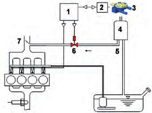
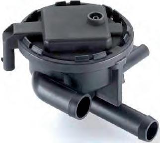
The NVLD system consists of an NVLD evaluation unit (see Fig. 2_439_11, 2 electronic part with temperature sensor) and an NVLD module (3 - pneumatic part). DME engine electronics 2
1 DME control unit 2 NVLD evaluation unit with temperature sensor 3 NVLD module (pneumatic part) 4 Carbon canister 5 Tank vent line 6 Tank vent valve 7 Throttle valve (electronic throttle)
DME engine electronics 2
2_440_11
2_441_11
Evaluation unit
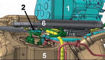
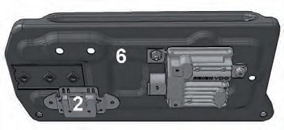
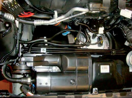
The installation position of the evaluation unit is directly above the fuel tank (see Fig. 2_440_11, 5), underneath the battery tray (6). The following components (electronic part, Fig. 2_442_11, 2) are also installed here: • Temperature sensor • Evaluation unit (self-diagnosing) with: –Timer –Memory –Communication interface with the DME control unit
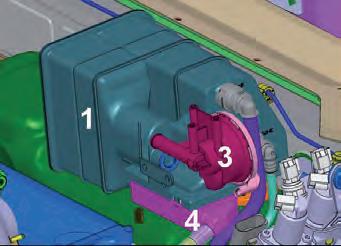
1 Carbon canister for USA (installed in front of the battery) 2 NVLD evaluation unit with temperature sensor (installed under the battery holder) 3 NVLD module (pneumatic part) 4 Ventilation filter 5 Fuel tank 6 Battery tray
The NVLD evaluation unit is connected to the switch in the NVLD module via a two-wire cable.
It is supplied externally with 12 volts and ground (terminal 30 + 31).
The third external connection on the NVLD evaluation unit is the communication line which is connected to the DME control unit.
2_442_11
Operating principle
The leak test is performed on the basis of Amontons’ Law (the Gas Law), which states that pressure is proportional to temperature in a closed system. This means that a change in pressure can be deduced from a change in temperature.
The system is sealed gas-tight (unlike previous methods) after the engine is switched off. This means that a change in temperature in the system will have a direct effect on the pressure.
The system is leak-free if a drop in temperature (long-term cooling) causes the pressure in the fuel tank to fall below -2.5 mbar relative pressure (vacuum relative to ambient pressure).
No-Leak Example
1
Pressure
2

Temperature
Tank pressure Reacts to Change in Temperature
Engine Cool Down and Other Environment Effects
Ø0.5 mm Leak Example
1
Pressure
2

Temperature 3 Time
No significant Change in Pressure Occurs
Engine Cool Down and Other Environment Effects
3 Time
2_444_11
2_445_11 DME engine electronics 2
The fuel tank ventilation system can be regarded as being leak-free if all leaks together correspond to a leak with a diameter of max. 0.4 mm (=0.016 inches).
The system is also leak-free if the pressure in the fuel tank after the engine is switched off is below -2.5 mbar relative pressure and this vacuum is maintained for at least 20 minutes.
1 Pressure curve in the tank system (red) 2 Temperature (blue) 3 Time
Figure 2_445_11 shows the long-term test for a system with a leak.
DME engine electronics 2
2_446_11
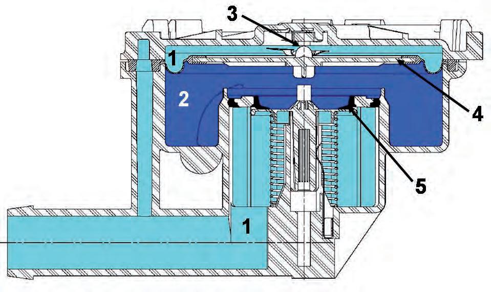
1 Vacuum (light blue) 2 Atmosphere (blue) 3 Switch (switching point -2.5 mbar; in Fig. 2_447_11) 4 Diaphragm 5 Conical seal
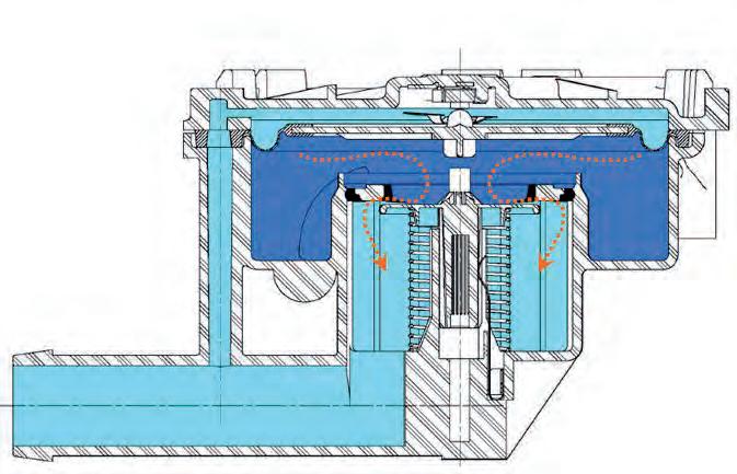
No. 6 (see Fig. 2_448_11) shows a leakfree system at maximum vacuum of -6.0 mbar.
The conical seal (5) limits the vacuum when the diaphragm is raised. Opens at -6.0 mbar, closes at -3.0 mbar.
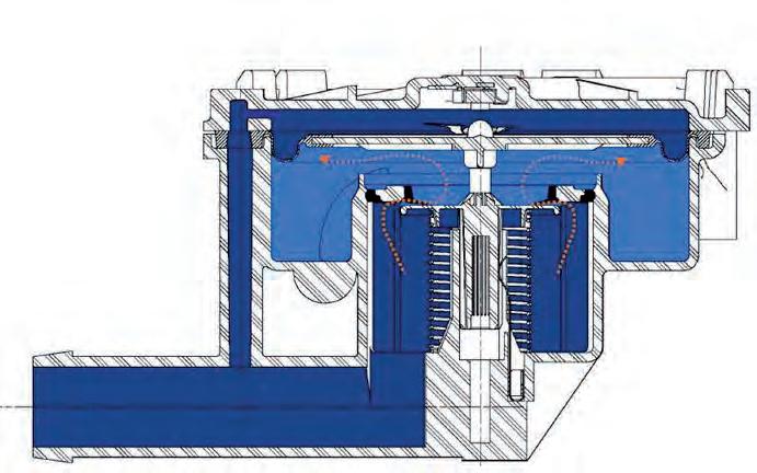
NVLD module (pneumatic part), operating principle under vacuum
This component (see Fig. 2_446_11) is located directly on the carbon canister. Figure 2_447_11 shows a leak-free system with the switching point of the vacuum switch at -2.5 mbar.
If long-term cooling causes a vacuum (1) of -2.5 mbar in the fuel tank after the vehicle is switched off, the diaphragm (4) moves upwards and closes the switch (3).
The electric vacuum switch (3) is actuated by vacuum when the diaphragm is raised. It closes and opens at -2.5 mbar relative vacuum.
NVLD: Mechanical Function –Vacuum at -6.0 mbar
6
–Vacuum –Atmosphere –Pressure 2_447_11
2_448_11
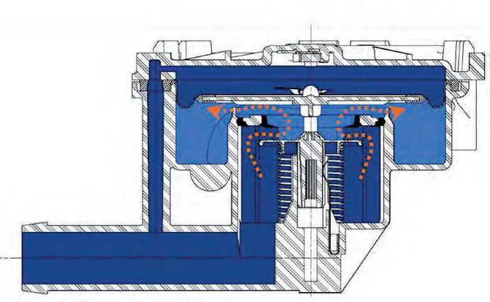
NVLD module (pneumatic part), operating principle under pressure
NVLD: Mechanical Function –At Rest
7
–Vacuum –Atmosphere –Pressure DME engine electronics 2
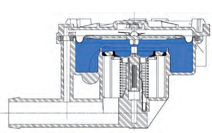
No. 7 (see Fig. 2_449_11) shows the NVLD module at ambient pressure. The ventilated NVLD module and diaphragm (4) are in neutral position.
No. 8 (see Fig. 2_450_11) shows the NVLD module at 1 mbar overpressure. The diaphragm moves downward in the event of overpressure and opens the conical seal (5). Opening starts at +1.0 mbar.
No. 9 (see Fig. 2_451_11) shows the NVLD module at +5 mbar (fully open at maximum overpressure).
In other words, the pressure in the fuel tank always moves between - 6.0 … +5.0 mbar in the stable condition.
NVLD: Mechanical Function –Pressure at + 1.0 mbar
8
–Vacuum –Atmosphere –Pressure 2_449_11
NVLD: Mechanical Function –Pressure at + 5 mbar
9
–Vacuum –Atmosphere –Pressure 2_450_11
DME engine electronics 2
Leak test
The NVLD tank leakage diagnostic system is passive. It works by measuring the pressure difference between the warm and cold fuel tank. In order to reliably determine the absence of leaks in the system, the fuel tank must be left to cool down for an extended period of time (e.g. overnight). This means that it is not possible to check whether the tank system is leak-free by means of a quick test using on-board diagnosis after a repair.
Consequently, a smoke test is provided for performing a quick leak test of the tank system using NVLD in the workshop. The smoke test is described in the PIWIS information system.
Note: On vehicles with NVLD, the DME actual value “E010” indicates whether the tank system was leak-free during the most recent long-term test in the stationary vehicle.
2_453_11


