Steering/Frame/Controls The following steering components should be inspected periodically to ensure safe and proper operation. A. Handlebar grips not worn, broken, or loose. B. Handlebar not bent, cracked, and has equal and complete full-left and full-right capability. C. Steering post bearing assembly/bearing housing not broken, worn, or binding.
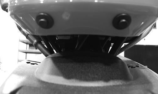
3. Remove the reinstallable rivets securing the steering post cover and remove the cover. 4. Unlatch the storage compartment lid; then slide the storage compartment cover assembly forward and lift off. 5. Remove the four cap screws securing the handlebar caps and instrument pod bracket to the steering post; then move the handlebar out of the way. Account for four handlebar caps. 6. Remove two cap screws securing the upper steering post bearing to the frame. Account for two bearings and two housings.
D. Ball joints not worn, cracked, or damaged. E. Tie rods not bent or cracked. F. Knuckles not worn, cracked, or damaged. G. Cotter pins not damaged or missing.
Steering Post/Tie Rods REMOVING 1. Remove the ignition switch retaining ring; then remove the reinstallable rivets securing the instrument pod to the mounting bracket and remove the pod. NOTE: It is not necessary to disconnect any wires from instrument pod components.
CD760
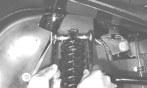
7. Using a suitable lift stand, raise the ATV enough to remove the front wheels; then remove the left-side and right-side splash panels.
CD685 CD759
2. Remove the reinstallable rivets securing the radiator access cover and remove the cover.
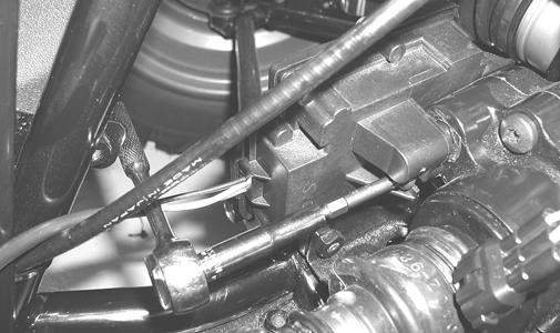
8. Remove the cotter pins and slotted nuts from the inner and outer tie rod ends; then remove the tie rods from the steering post arm and the left-side and rightside steering knuckles.
CD666
142
Manual Table of Contents
AF778D