39 minute read
Fuel/Lubrication/Cooling

NOTE: Some photographs and illustrations used in
this section are used for clarity purposes only and are not designed to depict actual conditions.
SPECIAL TOOLS A number of special tools must be available to the technician when performing service procedures in this section.
Tachometer
Description
Oil Pressure Test Kit
p/n
0644-275
0644-495
NOTE: Special tools are available from the Arctic
Cat Service Parts Department.
Diesel Fuel Injection System
The diesel engine in this Arctic Cat ATV is a “compression ignition” engine. Extremely high pressure in the combustion chamber raises air temperature high enough to cause ignition of the fuel upon injection into the combustion chamber. No spark is present or required for ignition.
In this style of engine, diesel fuel is drawn from the fuel tank by a low pressure lift pump. From the lift pump, fuel is pumped through the fuel filter/fuel shut-off and delivered to the fuel rail. Low pressure fuel at 0.42-0.56 kgcm2 (6-8 psi) flows to the unit injectors (high pressure fuel pump/fuel injector) where the fuel pump, driven by a special lobe on the camshaft, increases the fuel pressure to 143-153 kg-cm2 (2030-2175 psi). At this point, the fuel is atomized by the fuel injector nozzle as it enters the combustion chamber.
Fuel in excess of the amount required for any particular power setting is directed back into the fuel return side of the fuel rail and routed back to the fuel filter head where it either recirculates or is returned to the fuel tank via the fuel return hose.
Fuel flow is shut off when the ignition switch is turned to the OFF position. A fuel solenoid valve is located on the fuel filter head and opens the valve whenever a 12 DC volt current is applied to the solenoid.
Lift Pump
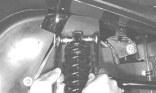
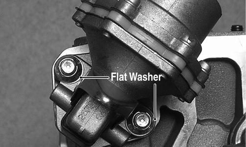
REMOVING 1.Remove the banjo-fitting bolts securing the fuel hoses to the lift pump; then remove the two nuts securing the lift pump to the cylinder head. Account for four crush washers, an O-ring, and two flat washers.
DE078B
DE309A
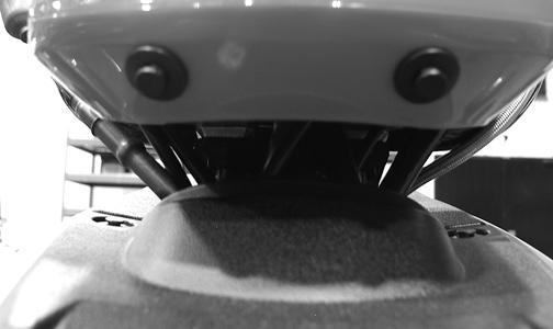
2.While holding pressure against the lift pump push rod, rotate the engine until the push rod is fully retracted.
NOTE: If pressure is not applied to the push rod
while rotating the engine, the push rod may become dislodged from the eccentric ring requiring valve cover removal to relocate.
INSTALLING 1.Using a new O-ring, place the fuel pump onto the cylinder head and secure with the existing hardware.
Tighten the nuts alternately until the fuel pump is seated against the head; then tighten securely.

DE530
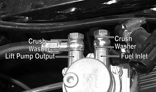
2.Connect the fuel inlet and lift pump outlet hoses to the fuel lift pump using new crush washers and secure with the banjo-fitting bolts. Tighten securely.
DE078A
Unit Injectors
To service the unit injectors, see Top-Side Components in Engine/Transmission.
Injector Timing
NOTE: For injector timing instructions, see Top-
Side Components in Engine/Transmission.
Fuel Filter
To replace the fuel filter, see Periodic Maintenance/TuneUp.
Fuel Solenoid Assembly
NOTE: After troubleshooting the fuel solenoid (see
Electrical System) if it is determined that replacement is necessary, use the following procedure.
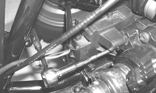
REMOVING 1.Remove the right-front inner splash panel; then remove the V-belt cooling boot from the V-belt housing. 2.Locate the fuel solenoid mounted on top of the fuel filter head; then disconnect the spade connector from the solenoid.


DE647B
3.Remove the banjo-fitting bolts (A) and (B) and remove the fuel solenoid. Account for four crush washers.

DE647A
INSTALLING 1.Using new crush washers, secure the fuel solenoid to the filter housing with banjo-fitting bolt (B) and tighten securely.
DE647A
2.Secure the fuel hose to the fuel solenoid with new crush washers and banjo-fitting bolt (A). 3.Connect the spade connector to the solenoid.
DE647B
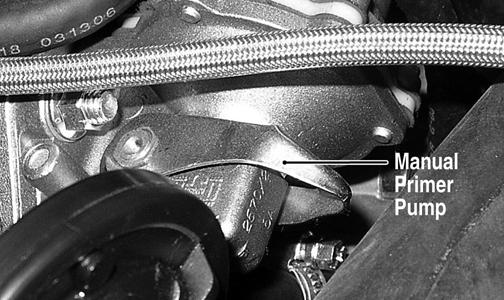
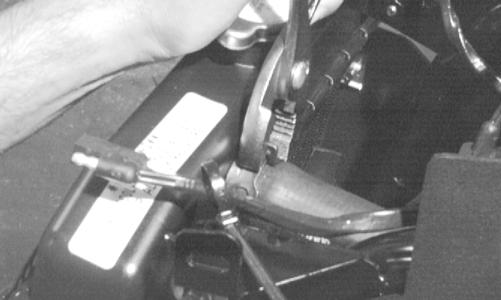
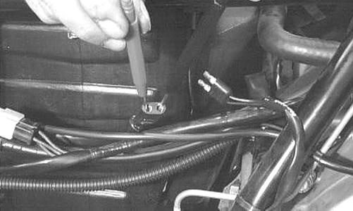
4.Bleed any air from the system by turning the ignition switch to the ON position and pumping the manual primer pump until resistance is felt.
DE031A
5.Start the engine and check for leaks; then shut off the engine and install the inner fender splash panel, right-side engine cover, and seat. Make sure the seat latches securely.
Fuel Tank
! WARNING
Whenever any maintenance or inspection is made on the fuel system during which there may be fuel leakage, there should be no welding, smoking, open flames, etc., in the area.
REMOVING
NOTE: Fuel tank removal should only be necessary
if the tank is leaking fuel or has been contaminated with water, dirt, or inadvertently filled with gasoline.
1.Remove the seat.
2.Remove the rear rack and fenders (see Steering/
Frame). 3.Disconnect the hose from the fuel tank to the lift pump; then disconnect the vent hose and fuel return hose.
4.Remove the cap screws securing the gas tank to the frame.
NOTE: Whenever a part is worn excessively,
cracked, or damaged in any way, replacement is necessary.
1.Remove the fuel level sensor and fuel pick-up screen. Account for a seal.
2.Completely drain all contaminated fuel from the fuel tank; then thoroughly wash the tank out with hot, soapy water. 3.Dry the tank interior with compressed air. NOTE: Repeat steps 2 and 3 until all contaminants
are removed.
4.Back-flush the fuel screen with hot, soapy water and dry with compressed air. NOTE: If any “pin-holes” are noted in the fuel
screen, replace the fuel level sensor assembly.
5.Inspect the tank cap and filler neck for chipped or broken threads.
6.Inspect the fuel tank mountings for security, signs of cracking, or wearing through the tank. 7.Inspect all fuel and vent hoses for cracks, softening, or deterioration. Replace as required. INSTALLING 1.Place the fuel tank into position in the frame; then install the cap screws. Tighten securely. 2.Connect the fuel hose from the lift pump; then connect the fuel gauge connector. 3.Install the vent hose and fuel return hose; then fill the fuel tank with clean diesel fuel.
4.Replace the fuel filter (see Periodic Maintenance/
Tune-Up). 5.Pump the manual primer pump 12-20 strokes; then start the engine and inspect for leakage. 6.Install the rear fenders and rack (see Steering/
Frame); then install the seat making sure it latches securely.
Fuel/Vent Hoses
Replace the fuel hoses every two years. Damage from aging may not always be visible. Do not bend or obstruct the routing of the vent hose or fuel return hose.
Oil Filter/Oil Pump
NOTE: Whenever internal engine components wear
excessively or break and whenever oil is contaminated, the oil pump should be replaced. The oil pump is not a serviceable component.
Testing Oil Pump Pressure
NOTE: The engine must be warmed up to the speci-
fied temperature for this test (see Engine/Transmission - Specifications).
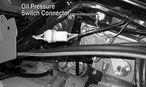
1.Connect the Tachometer to the engine. 2.Disconnect the oil pressure switch connector; then connect the Oil Pressure Test Kit to the oil pressure switch port.
DE077B
NOTE: Some oil seepage may occur when installing
the oil pressure gauge. Wipe up oil residue with a cloth.
3.Start the engine and run at the recommended RPM.
The oil pressure gauge must read as specified (see
Engine/Transmission - Specifications). NOTE: If oil pressure is lower than specified, check
for an oil leak, damaged oil seal, defective oil pump, or oil cooler.
NOTE: If oil pressure is higher than specified, check
for too heavy engine oil weight (see General Information - Fuel-Oil-Lubricant), clogged oil passage, clogged oil filter, or improper installation of the oil filter.
Liquid Cooling System
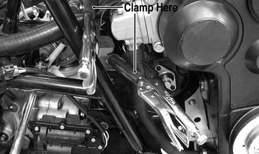
To check the cooling system, see Periodic Maintenance/ Tune-Up. DRAINING COOLANT The cooling system does not have a drain; therefore, coolant must be removed using the following procedure. 1.Using suitable in-line clamps, close off the lower radiator hose and the coolant bypass hose next to the water pump.
DE510A
2.Place a suitable drain pan with a capacity of at least 4 l (4.2 U.S. qt) under the left front of the engine; then loosen the hose clamp on the coolant bypass hose. 3.Remove the hose and allow coolant to drain into the drain pan. A funnel or short hose can be used to direct coolant into the drain pan. 4.Install the coolant bypass hose and tighten the clamp securely; then remove the in-line clamps. FILLING COOLANT 1.Elevate the rear of the ATV approximately 30 cm (12 in.) and secure in place using appropriate blocks.
2.Remove the cap from the filler neck (located under the service access cover) and slowly pour the recommended amount of coolant into the system. 3.Move the ATV outside or to a well-ventilated area and start the engine allowing it to run for several minutes; then remove the filler cap and check the coolant level. Add coolant as required until coolant is visible within one inch of the top of the filler neck. 4.Install the filler cap on the filler neck and tighten until the cap contacts the stop.
CAUTION
Failure to elevate the rear of the ATV may result in air being trapped in the cooling system causing severe engine damage due to overheating.
! WARNING
Do not over-tighten coolant filler cap or excess pressure will build up in the cooling system causing cooling system damage and possible bodily harm.
Radiator
REMOVING 1.Drain the coolant at the engine. 2.Remove the front rack (see Steering/Frame). 3.Remove the front bumper and front fender panel (see
Steering/Frame). 4.Remove the upper and lower coolant hoses.
6.Disconnect the fan wiring from the main wiring harness; then remove the radiator/fan assembly and account for the grommets and collars. 7.Remove the fan/fan shroud assembly from the radiator.
Hoses/Thermostat
CC863
CLEANING AND INSPECTING
NOTE: Whenever a part is worn excessively,
cracked, or damaged in any way, replacement is necessary.
1.Flush the radiator with water to remove any contaminants.
2.Inspect the radiator for leaks and damage. 3.Inspect all hoses for cracks and deterioration. 4.Inspect all fasteners and grommets for damage or wear. INSTALLING 1.Position the fan/fan shroud assembly on the radiator; then secure with existing hardware. 2.Place the radiator with grommets and collars into position on the frame; then install the cap screws and nuts. Tighten securely. 3.Install the upper and lower coolant hoses; then secure with hose clamps.
AF734D
4.Install the front bumper and front fender panel (see
Steering/Frame). 5.Install the front rack (see Steering/Frame). 6.Fill the cooling system with the recommended amount of antifreeze. Check for leakage. 7.Connect the fan wiring to the main wiring harness.
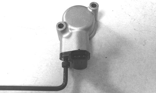
REMOVING 1.Drain approximately two quarts of coolant from the cooling system. 2.Remove the two cap screws securing the thermostat cover housing to the thermostat housing. Account for an O-ring and a thermostat. INSPECTING NOTE: Whenever a part is worn excessively,
cracked, or damaged in any way, replacement is necessary.
1.Inspect the thermostat for corrosion, wear, or spring damage. 2.Using the following procedure, inspect the thermostat for proper operation.
A.Suspend the thermostat in a container filled with water.
B.Heat the water and monitor the temperature with a thermometer.
C.The thermostat should start to open at 80° C (176° F) and be fully open at 95° C (203° F).
D.If the thermostat does not open or remains open, it must be replaced. 3.Inspect all coolant hoses, connections, and clamps for deterioration, cracks, and wear. NOTE: All coolant hoses and clamps should be
replaced every four years or 4000 miles.
INSTALLING 1.Place the thermostat and O-ring into the thermostat housing; then secure the thermostat housing to the cylinder head with the two cap screws. 2.Install the crossover coolant hose onto the water pump and engine water inlet. Secure with the two hose clamps. 3.Slide the upper hose onto the thermostat housing and radiator. Secure with the two hose clamps. 4.Install the lower coolant hose onto the water pump housing and radiator. Secure with the two hose clamps. 5.Fill the cooling system with the recommended amount of antifreeze. Check for leakage.
Fan
REMOVING 1.Remove the radiator (see Radiator in this section). 2.Remove the fan assembly from the radiator. INSTALLING 1.Position the fan assembly on the radiator; then secure with existing hardware.
NOTE: The fan wiring must be in the upper-right
position.
2.Install the radiator (see Radiator in this section).
Water Pump
NOTE: The water pump is a non serviceable compo-
nent and must be replaced as an assembly.
To replace the water pump, see Engine/Transmission Left-Side Components.
Troubleshooting
Problem: Starting impaired Condition Remedy
1. Fuel contaminated 1.Drain fuel tank and fill with clean fuel
Problem: Idling or low speed impaired Condition Remedy
1. Fuel filter plugged 1.Replace fuel filter
Problem: Medium or high speed impaired Condition Remedy
1. Governor spring broken 1.Replace speed governor spring 2. Fuel filter obstructed 2.Replace filter 3. Throttle cable out of adjustment 3.Adjust throttle cable
Electrical System
The electrical connections should be checked periodically for proper function. In case of an electrical failure, check fuses, connections (for tightness, corrosion, damage), and/or bulbs. SPECIAL TOOLS A special tool must be available to the technician when servicing the electrical system.
Description
Fluke Model 77 Multimeter
p/n
0644-559
NOTE: Special tools are available from the Arctic
Cat Service Parts Department.
Battery
The battery is located in a compartment in front of the left-rear wheel under the driver seat.
NOTE: To access the battery box, the left-rear
fender splash panel must be removed.
After being in service, batteries require regular cleaning and recharging in order to deliver peak performance and maximum service life. The following procedures are recommended for cleaning and maintaining lead-acid batteries. Always read and follow instructions provided with battery chargers and battery products. NOTE: Refer to all warnings and cautions provided
with the battery or battery maintainer/charger.
Loss of battery charge may be caused by ambient temperature, ignition OFF current draw, corroded terminals, self discharge, frequent start/stops, and short engine run times. Frequent winch usage, snowplowing, extended low RPM operation, short trips, and high amperage accessory usage are also reasons for battery discharge. Maintenance Charging NOTE: Arctic Cat recommends the use of the CTEK
Multi US 800 or the CTEK Multi US 3300 for battery maintenance charging. Maintenance charging is required on all batteries not used for more than two weeks or as required by battery drain.
1.When charging a battery in the vehicle, be sure the ignition switch is in the OFF position. NOTE: Be sure to maintain the fluid of the battery at
the UPPER LEVEL. Use only distilled water when adding fluid to these batteries.
4.Connect the red terminal lead from the charger to the positive terminal of the battery; then connect the black terminal lead of the charger to the negative terminal of the battery. NOTE: Optional battery charging adapters are avail-
able from your authorized Arctic Cat dealer to connect directly to your vehicle from the recommended chargers to simplify the maintenance charging process. Check with your authorized Arctic Cat dealer for proper installation of these charging adapter connectors.
5.Plug the battery charger into a 110-volt electrical outlet.
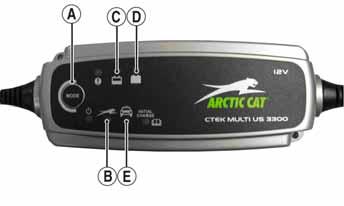
6.If using the CTEK Multi US 800, there are no further buttons to push. If using the CTEK Multi US 3300, press the Mode button (A) at the left of the charger until the Maintenance Charge Icon (B) at the bottom illuminates. The Normal Charge Indicator (C) should illuminate on the upper portion of the battery charger.
800E
NOTE: The maintainer/charger will charge the bat-
tery to 95% capacity at which time the Maintenance Charge Indicator (D) will illuminate and the maintainer/charger will change to pulse/float maintenance. If the battery falls below 12.9 DC volts, the charger will automatically start again at the first step of the charge sequence.
3300A
2.Clean the battery terminals with a solution of baking soda and water.
3.Be sure the charger and battery are in a well-ventilated area and ensure the battery charger cables will not contact any battery acid. Be sure the charger is unplugged from the 110-volt electrical outlet.
NOTE: Not using a battery charger with the proper
float maintenance will damage the battery if connected over extended periods.
NOTE: Arctic Cat recommends the use of the CTEK
Multi US 800 or the CTEK Multi US 3300 for battery maintenance charging.
1.Be sure the battery and terminals have been cleaned with a baking soda and water solution. 2.Be sure the charger and battery are in a well-ventilated area and ensure the battery charger cables will not contact any battery acid. Be sure the charger is unplugged from the 110-volt electrical outlet. 3.Connect the red terminal lead from the charger to the positive terminal of the battery; then connect the black terminal lead of the charger to the negative terminal of the battery. 4.Plug the charger into a 110-volt electrical outlet. 5.By pushing the Mode button (A) on the left side of the charger, select the Normal Charge Icon (E). The
Normal Charge Indicator (C) should illuminate on the upper left portion of the charger. 6.The battery will charge to 95% of its capacity at which time the Maintenance Charge Indicator (D) will illuminate.
NOTE: For optimal charge and performance, leave
the charger connected to the battery for a minimum 1 hour after the Maintenance Charge Indicator (D) illuminates. If the battery becomes hot to the touch, stop charging. Resume after it has cooled.
7.Once the battery has reached full charge, unplug the charger from the 110-volt electrical outlet. NOTE: If, after charging, the battery does not perform
to operator expectations, bring the battery to an authorized Arctic Cat dealer for further troubleshooting.
Testing Electrical Components
All of the electrical tests should be made using the Fluke Model 77 Multimeter. If any other type of meter is used, readings may vary due to internal circuitry. When troubleshooting a specific component, always verify first that the fuse(s) are good, that the bulb(s) are good, that the connections are clean and tight, that the battery is fully charged, and that all appropriate switches are activated. NOTE: For absolute accuracy, all tests should be
made at room temperature of 68° F.
Switches
Each time the ATV is used, switches should be checked for proper operation. Use the following list for reference.
B.Emergency stop switch — engine will stop. C.Reverse switch — reverse indicator light will illuminate.
D.Hi/Lo switch — headlight beam bright and dim. E.Brake switches — rear brakelight will illuminate.
Accessory Receptacle/ Connector
NOTE: This test procedure is for either the recepta-
cle or the connector.
VOLTAGE 1.Turn the ignition switch to the ON position; then set the meter selector to the DC Voltage position. 2.Connect the red tester lead to the red/white wire or the positive connector; then connect the black tester lead to ground. 3.The meter must show battery voltage. NOTE: If the meter shows no battery voltage, trou-
bleshoot the battery, fuse, receptacle, connector, or the main wiring harness.
Brakelight Switch (Auxiliary)
The switch connector is the two-prong connector on the brake switch lead above the transmission.
NOTE: The ignition switch must be in the ON posi-
tion.
VOLTAGE (Wiring Harness Side) 1.Set the meter selector to the DC Voltage position. 2.Connect the red tester to the orange wire; then connect the black tester lead to ground.
AR627D
3.The meter must show battery voltage. NOTE: If the meter shows no battery voltage, trou-
bleshoot the battery, fuse, switch, or the main wiring harness.
NOTE: If the meter shows battery voltage, the main
wiring harness is good; proceed to test the switch/ component, the connector, and the switch wiring harness for resistance.
RESISTANCE (Switch Connector) 1.Set the meter selector to the OHMS position. 2.Connect the red tester lead to one black wire; then connect the black tester lead to the other black wire.
AR626D
3.When the brake pedal is depressed, the meter must show less than 1 ohm.
NOTE: If the meter shows more than 1 ohm of resis-
tance, replace the switch.
Brakelight Switch (Handlebar Control)
To access the connector, remove the access panel. NOTE: The ignition switch must be in the ON posi-
tion.
VOLTAGE (Wiring Harness Connector) 1.Set the meter selector to the DC Voltage position. 2.Connect the red tester lead to the orange wire; then connect the black tester lead to ground.

AR622D
NOTE: If the meter shows no battery voltage, trou-
bleshoot the battery, fuse, switch, or the main wiring harness.
NOTE: If the meter shows battery voltage, the main
wiring harness is good; proceed to test the switch/ component, the connector, and the switch wiring harness for resistance.
RESISTANCE (Switch Connector)
NOTE: The brake lever must be compressed for this
test. Also, the ignition switch must be in the OFF position.
1.Set the meter selector to the OHMS position. 2.Connect the red tester lead to one black wire; then connect the black tester lead to the other black wire.
AR621D
3.When the lever is compressed, the meter must show less than 1 ohm.
NOTE: If the meter shows more than 1 ohm of resis-
tance, replace the switch.
Cooling Fan Switch
1.Connect the meter leads (selector in OHMS position) to the cooling fan switch terminals. 2.Suspend the switch and a thermometer in a container of water; then heat the water. NOTE: Neither the switch nor the thermometer
should be allowed to touch the bottom of the container or inaccurate readings will occur. Use wire holders to suspend the switch and thermometer.
3.When the water temperature reaches approximately 93° C (199° F), the meter should read less than 1.0 ohm.
4.Allow the water to cool and when the temperature reaches approximately 87° C (189° F), the meter should read an open circuit.
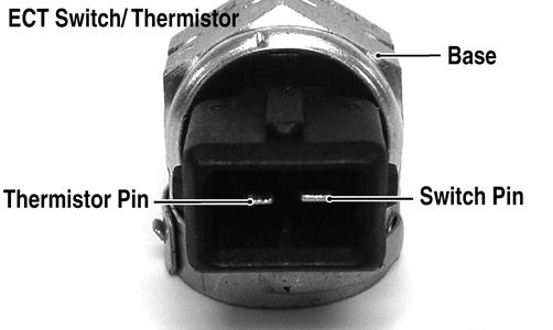
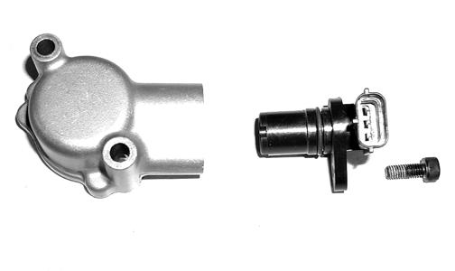
The ECT switch/thermistor is a two-function device. One side is a normally open, temperature activated switch that closes when high coolant temperature is detected activating the high temperature circuit in the speedometer/LCD. The other side contains a temperature sensitive resistor (thermistor) that provides temperature information to the glow plug controller/relay. To test the ECT switch/thermistor, use the following procedure. 1.Suspend the ECT switch/thermistor and a thermometer in a container of cooking oil. NOTE: Neither the ECT switch/thermistor nor the
thermometer should be allowed to touch the bottom of the container or inaccurate readings will occur. Use wire holders to suspend the ECT switch/thermistor and thermometer.
2.Connect one meter lead to the base of the switch/ thermistor and the other meter lead to the switch pin.
With the meter in the OHMS position, the meter should read an open circuit.
DE650A
3.Remove the meter lead from the switch pin and connect to the thermistor pin; then heat the oil and note the temperature and meter readings. 4.When the temperature reaches 20° C (68° F), the meter should read 1k ohms.
5.When the temperature reaches 40° C (104° F), the meter should read 460 ohms.
6.When the temperature reaches 50° C (122° F), the meter should read 320 ohms.
7.Remove the meter lead from the thermistor pin and connect to the switch pin; then continue to heat the oil.
8.When the temperature reaches approximately 110° C (230° F), the meter should read less than 1 ohm. ! WARNING
Wear insulated gloves and safety glasses. Heated oil can cause severe burns.
Glow Plug Controller/ Relay
The glow plug controller/relay is a plug-in device located under the seat. The glow plug controller/relay applies 12 DC volts to the glow plugs in the pre-combustion chambers to aid in cold starting. Heating time is determined by the ECT thermistor signal and will vary from 0 seconds (warm engine) to approximately 30 seconds (cold engine). NOTE: The glow plug controller/relay is not a ser-
viceable component. To test the controller/relay, use the following procedure.
1.Using an appropriate multimeter, select DC Volts and connect the black (-) tester lead to the black (85) wire and the red (+) tester lead to the red/orange (30) wire. The meter must read battery voltage. If no battery voltage is present, check the connection at the starter relay. 2.Connect the red tester lead to the white/blue (87) wire and momentarily turn the ignition switch to the
ON position. The meter should read battery voltage for up to 30 seconds; then drop to zero. 3.Connect the red tester lead to the yellow/orange (L) wire and turn the ignition switch to the ON position. The meter should read battery voltage and the green glow plug indicator should illuminate for up to 30 seconds. 4.Turn the ignition switch off. 5.Turn the ignition switch to the ON position. Observe the glow plug indicator while momentarily “bumping” the starter button. The glow plug indicator should immediately extinguish. 6.If steps 2, 3, or 5 are not as specified, replace the glow plug controller/relay. 7.If the glow plugs remain on for more than 35 seconds, test the ECT switch/thermistor (thermistor side only). NOTE: To test the glow plugs, use the following pro-
cedure.
1.Disconnect the white/blue glow plug power wire from the right-side glow plug; then disconnect the jumper wire running to the left-side glow plug.
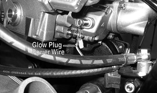
2.Select the OHMS position on a suitable tester; then connect one tester lead to a suitable ground and the other tester lead to the glow plug center connector.
The meter must read less than 1 ohm.
3.If the meter reading is not as specified, replace the affected glow plug.
Fan Motor
The connector is the black two-prong one located behind the fan assembly. NOTE: The ignition switch must be in the ON position. VOLTAGE (Main Harness Connector to Fan Motor) 1.Set the meter selector to the DC Voltage position. 2.Connect the red tester lead to the black/red wire; then connect the black tester lead to ground. 3.The meter must show battery voltage. NOTE: If the meter shows no battery voltage, trou-
bleshoot the battery, fuse, motor, or the main wiring harness.

NOTE: If the meter shows battery voltage, the main
wiring harness is good. The connector should be checked for resistance.
RESISTANCE (Fan Motor Connector) 1.Set the meter selector to the OHMS position. 2.Connect the red tester lead to the blue wire; then connect the black tester lead to the black wire.
AR645D
3.The meter must show less than 1 ohm.
NOTE: If the meter shows more than 1 ohm of resis-
tance, troubleshoot or replace the switch/component, the connector, or the switch wiring harness.
NOTE: To determine if the fan motor is good, con-
nect the blue wire from the fan connector to a 12 volt DC power supply; then connect the black wire from the fan connector to ground. The fan should operate.
Care should be taken to keep clear of the fan blades.
Fuse Block/Power Distribution Module
The fuses are located in a power distribution module under the seat. If there is any type of electrical system failure, always check the fuses first. NOTE: The ignition switch must be in the LIGHTS
position.
700 Diesel
1411-381
CAUTION
Always replace a blown fuse with a fuse of the same type and rating.
1.Remove all fuses from the distribution module.
NOTE: To remove a fuse, compress the locking tabs
on either side of the fuse case and lift out.
2.Set the meter selector to the DC Voltage position. 3.Connect the black tester lead to ground. 4.Using the red tester lead, contact each end of the fuse holder connector terminals individually. 5.The meter must show battery voltage from one side of the connector terminal ends.
NOTE: Battery voltage will be indicated from only
one side of the fuse holder connector terminal; the other side will show no voltage.
NOTE: When testing the HI fuse holder, the head-
light dimmer switch must be in the HI position; when testing the LIGHTS fuse holder, the headlight dimmer switch can be in either position.
NOTE: If the meter shows no battery voltage, trou-
bleshoot the battery, switches, distribution module, or the main wiring harness.
FUSES 1.Set the meter selector to the OHMS position. 2.Connect the red tester lead to one spade end of the fuse; then connect the black tester lead to the other spade end.
3.The meter must show less than 1 ohm resistance. If the meter reads open, replace the fuse. NOTE: Make sure the fuses are returned to their
proper position according to amperage. Refer to the fuse block cover for fuse placement.
RELAYS The relays are identical plug-in type located on the power distribution module. Relay function can be checked by switching relay positions. The relays are interchangeable. NOTE: The module and wiring harness are not a
serviceable component and must be replaced as an assembly.
Speed Sensor
NOTE: Prior to testing the speed sensor, inspect the
three-wire connector on the speed sensor for contamination, broken pins, and/or corrosion.
1.Set the meter selector to the DC Voltage position. 2.With appropriate needle adapters on the meter leads, connect the red tester lead to the voltage lead (V); then connect the black tester lead to the ground lead (G).

CD885A
3.Turn the ignition switch to the ON position. 4.The meter must show 6 DC volts.
5.Leave the black tester lead connected; then connect the red tester lead to the signal lead (S) pin. 6.Slowly move the ATV forward or backward; the meter must show 0 and 6 DC volts alternately. NOTE: If the sensor tests are within specifications,
the speedometer must be replaced (see Controls/Indicators).
To replace a speed sensor, use the following procedure. 1.Disconnect the three-wire connector from the speed sensor harness or from the speed sensor; then remove the Allen-head cap screw securing the sensor to the sensor housing. 2.Remove the sensor from the sensor housing accounting for an O-ring.
CD070
3.Install the new speed sensor into the housing with new O-ring lightly coated with multi-purpose grease; then secure the sensor with the Allen-head cap screw (threads coated with blue Loctite #242). Tighten securely.
CD071
Ignition Switch
The connector is a four-wire one. To access the connector, the cover must be removed. VOLTAGE NOTE: Perform this test on the lower side of the
connector.
1.Set the meter selector to the DC Voltage position. 2.Connect the red meter lead to the red wire; then connect the black meter lead to ground. 3.Meter must show battery voltage. NOTE: If the meter shows no battery voltage, trou-
bleshoot the battery or the main wiring harness.
RESISTANCE NOTE: Perform this test on the upper side of the
connector.
1.Turn the ignition switch to the ON position. 2.Set the meter selector to the OHMS position. 3.Connect the red tester lead to the red wire; then connect the black tester lead to the red/black wire.
5.Turn the ignition switch to the LIGHTS position. 6.Connect the red tester lead to the red wire; then connect the black tester lead to the red/black wire.
7.The meter must show less than 1 ohm.
8.Connect the red tester lead to the red wire; then connect the black tester lead to the gray wire. 9.The meter must show less than 1 ohm.
10.With the switch in the OFF position, connect the red tester lead to the red wire and the black tester lead to each of the remaining wires. The meter must show an open circuit on all wires. 11.Connect the red tester lead to the red wire and the black tester lead to the brown wire. With the switch in the ON position, the meter must show 980-1020 ohms.
NOTE: If the meter shows more than 1 ohm of resis-
tance, troubleshoot or replace the switch/component, the connector, or the switch wiring harness.
Handlebar Control Switches
The connector is the yellow one next to the steering post. To access the connector, the steering post cover and the right-side fender splash shield must be removed (see Steering/Frame). NOTE: These tests should be made on the top side
of the connector.
CAUTION
Always disconnect the battery when performing resistance tests to avoid damaging the multimeter.
RESISTANCE (HI Beam) 1.Set the meter selector to the OHMS position. 2.Connect the red tester lead to the yellow wire; then connect the black tester lead to the gray wire. 3.With the dimmer switch in the HI position, the meter must show less than 1 ohm.
NOTE: If the meter shows more than 1 ohm of resis-
tance, troubleshoot or replace the switch/component, the connector, or the switch wiring harness.
RESISTANCE (LO Beam) 1.Connect the red tester lead to the white wire; then connect the black tester lead to the gray wire. 2.With the dimmer switch in the LO position, the meter must show an open circuit. NOTE: If the meter reads resistance, troubleshoot
or replace the switch/component, the connector, or the switch wiring harness.
NOTE: If voltage is not as specified, check the con-
dition of the battery in the meter prior to replacing the switch. A low battery will result in a low voltage reading during a diode test.
1.Set the meter selector to the DIODE position. 2.Connect the red tester lead to the orange/white wire; then connect the black tester lead to the yellow/green wire.
3.With the starter button depressed, the meter must show 0.5-0.7 DC volts.
4.With the starter button released, the meter must show 0 DC volts.
5.Connect the red tester lead to the yellow/green wire; then connect the black tester lead to the orange/white wire.
6.With the starter button depressed, the meter must show 0 DC volts.
NOTE: If the meter does not show as specified,
replace the switch/component, connector, or switch harness.
RESISTANCE (Emergency Stop) 1.Set the meter selector to the OHMS position. 2.Connect the red tester lead to the orange wire; then connect the black tester lead to the orange/white wire.
3.With the switch in the OFF position, the meter must show an open circuit. 4.With the switch in the RUN position, the meter must show less than 1 ohm.
NOTE: If the meter shows more than 1 ohm of resis-
tance, troubleshoot or replace the switch/component, the connector, or the switch wiring harness.
Drive Select Switch
The connector is the three-wire white snap-lock one in front of the steering post. To access the connector, the cover must be removed.
NOTE: Resistance tests should be made with the
connector disconnected and on the selector-side of the connector.
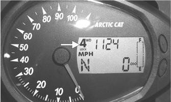
RESISTANCE 1.Set the meter selector to the OHMS position. 2.Connect the red tester lead to the orange wire; then connect the black tester lead to the green/white wire. 3.With the selector switch in the 4WD position, the meter must show less than 1 ohm.
4.Connect the black tester lead to the black wire; then select the 4WD LOCK position. The meter should show less than 2 ohms.
NOTE: If the meter does not show as specified,
replace the front drive selector switch.
VOLTAGE
NOTE: The battery must be connected when per-
forming voltage tests.
1.Set the meter selector to the DC Voltage position. 2.Connect the black tester lead to black wire on the harness side of the connector.
3.Connect the red tester lead to the white/orange wire on the harness side of the connector.
4.Turn the ignition switch to the RUN position. 5.The meter must show approximately 8 DC volts. NOTE: If the meter shows other than specified,
check the harness, connector, 30 amp fuse, and battery connections.
Front Drive/Differential Lock Actuator
NOTE: With the engine stopped and the ignition
switch in the ON position, a momentary “whirring” sound must be noticeable each time the selector switch is moved to 2WD and 4WD. Test the switch, 30 amp fuse, and wiring connections prior to testing the actuator.
NOTE: The differential must be in the unlocked
position for this procedure.
VOLTAGE 1.Select the 2WD position on the front drive selector switch; then disconnect the connector on the actuator wiring harness. 2.With the ignition switch in the OFF position, connect the black tester lead to the black wire in the supply harness; then connect the red tester lead to the orange wire in the supply harness. 3.Turn the ignition switch to the ON position. The meter must show approximately 11 DC volts. 4.Connect the red tester lead to the white/orange wire in the supply harness. The meter must show approximately 6 DC volts. 5.Connect the red tester lead to the white/green wire in the supply harness. The meter must show approximately 10 DC volts. 6.Select the 4WD position on the front drive selector switch; then connect the red tester lead to the white/ orange wire in the supply harness. The meter must show 12 DC volts.
NOTE: The 4WD icon on the LCD should illuminate.
7.Connect the red tester lead to the white/green wire in the supply harness. The meter must show 0 DC volts. 8.Select Differential Lock on the front drive actuator switch; then connect the red tester lead to the white/ orange wire in the supply harness. The meter must show 0 DC volts.
9.Connect the tester lead to the white/green wire in the supply harness. The meter must show 0 DC volts. NOTE: The 4WD and LOCK icons on the LCD
should illuminate.
NOTE: If the voltage readings are as specified and
the actuator does not function correctly, replace the actuator (see Drive System).
CF094C
Starter/Starter Solenoid
NOTE: The starter is not a serviceable component
and must be replaced as an assembly. Before replacing the starter, troubleshoot the starter voltage, starter relay, neutral start, and start-in-gear relays.
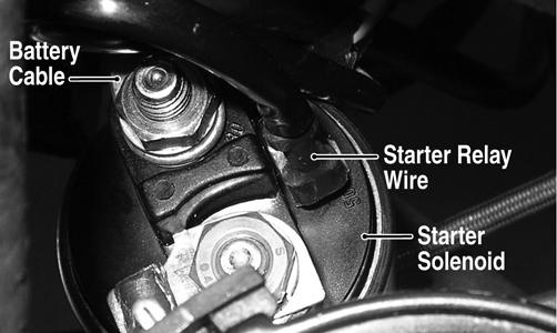
To replace the starter, use the following procedure. REMOVING 1.Remove the negative battery cable from the battery. 2.Remove the left-side inner fender splash panel; then remove the seat and the left-side engine cover. 3.Disconnect the battery cable and the starter wire from the starter solenoid; then remove the two cap screws securing the starter to the V-belt housing. INSTALLING 1.Place the starter into position in the V-belt housing; then secure with the two cap screws and tighten to 35 ft-lb.
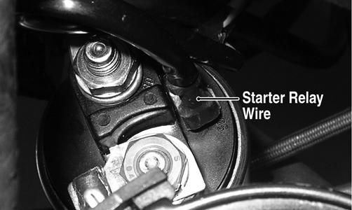
2.Connect the battery cable to the starter solenoid; then connect the starter relay wire to the spade terminal on the starter solenoid.
DE653A
3.Install the inner splash panel, engine cover, and seat; then connect the negative battery cable to the battery.
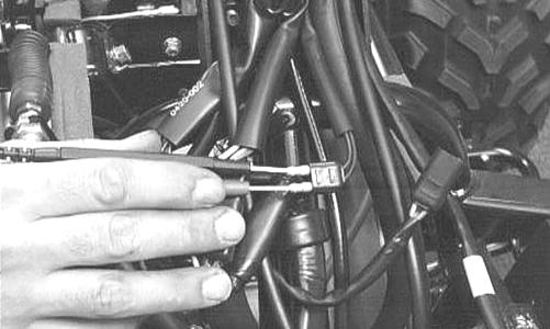
Tighten securely. TESTING VOLTAGE Perform this test on the starter solenoid starter relay terminal.
NOTE: The ignition switch must be in the ON posi-
tion, the emergency stop switch in the RUN position, and the shift lever in the NEUTRAL position.
1.Set the meter selector to the DC Voltage position. 2.Connect the red tester lead to the spade terminal; then connect the black tester lead to ground.
DE653B
3.With the starter button depressed, the meter must show battery voltage and the starter motor should operate. NOTE: If the meter showed battery voltage but the
starter did not operate or operated slowly, inspect battery voltage (at the battery), starter motor condition, and/or ground connections.
NOTE: If the meter showed no battery voltage,
inspect the main fuse, ground connections, starter motor lead, battery voltage (at the battery), starter relay, or the neutral start relay.
Starter Relay
DE002B
NOTE: Make sure that the ignition switch is in the
ON position, transmission in neutral, brake lock released, and the emergency stop switch in the RUN position.
3.Depress the starter button while observing the multimeter. The multimeter should drop to 0 volts and a
“click” should be heard from the relay. NOTE: If a “click” is heard and any voltage is indi-
cated by the multimeter, replace the starter relay. If no “click” is heard and the multimeter continues to indicate battery voltage, proceed to step 4.
4.Disconnect the two-wire plug from the starter relay; then connect the red tester lead to the green wire and the black tester lead to the black wire.
5.Depress the starter button and observe the multimeter.
NOTE: If battery voltage is indicated, replace the
starter relay. If no voltage is indicated, check Neutral Start relay (see Fuse Block/Power Distribution Module in this section).
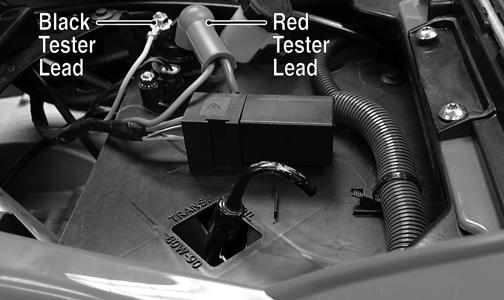
Alternator/Regulator
TESTING Prior to performing the following tests, make sure the alternator belt is properly tightened and the battery is fully charged. 1.Using a suitable multimeter, select the DC Voltage position; then connect the red tester lead to the positive battery post and the black tester lead to the negative battery post. 2.Start the engine and slowly increase RPM. The voltage should increase with the engine RPM to a maximum of 15.5 DC volts.
1.Remove the seat; then using the multimeter set to the DC Voltage position, check the relay as follows. 2.Connect the red tester lead to the battery terminal; then connect the black tester lead to the starter solenoid cable connection on the starter relay. The meter must show battery voltage.
NOTE: If voltage rises above 15.5 DC volts, the reg-
ulator is faulty or a battery connection is loose or corroded. Clean and tighten battery connections or replace the alternator. If voltage does not rise, check all battery connections, the battery (B+) wire on the alternator, and the voltage regulator control plug-in. If all are normal, replace the alternator.
REMOVING 1.Remove the negative battery cable from the battery; then remove the seat and left-side engine cover. 2.Disconnect the battery (B+) wire from the alternator; then disconnect the voltage regulator control plug-in.

DE519B
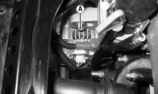
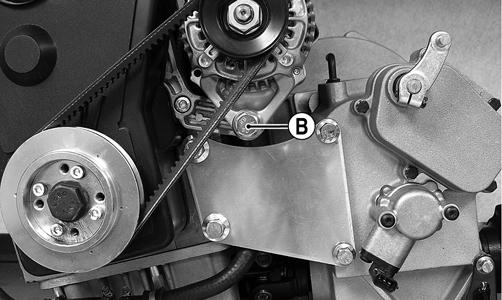
3.Loosen the alternator adjuster cap screw (A) and the pivot bolt (B); then remove the alternator drive belt.
DE519C
DE103C
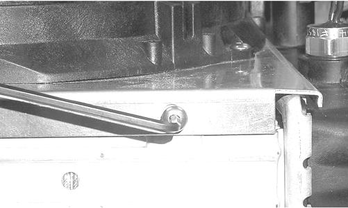
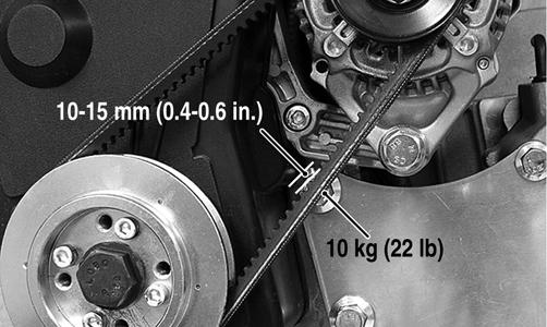
4.Remove the adjuster cap screw and pivot bolt and remove the alternator. INSTALLING 1.Place the alternator/regulator into position on the engine; then secure with the existing hardware. Do not tighten at this time. 2.Place the alternator drive belt into position; then using a suitable pry, tension the drive belt so that a 10 kg (22 lb) force applied at the midway point will result in a deflection of 10-15 mm (0.4-0.6 in.).
DE103B
3.Holding tension on the belt, tighten the adjuster cap screw securely; then remove the pry and tighten the pivot bolt securely. 4.Connect the battery (B+) wire and connect the regulator control plug-in; then connect the negative battery cable to the battery. 5.Install the left-side engine cover and seat making sure the seat latches securely.
Headlights
The connectors are the four 2-prong ones secured to the front bumper supports (two on each side) with cable ties. BULB VERIFICATION (Low and High Beam) NOTE: Perform this test on each headlight bulb.
Also, a 12-volt external power supply w/jumpers will be needed.
1.Disconnect the wiring harness from the bulb to be tested.
2.Connect the power supply (positive) to one bulb contact; then connect the power supply (negative) to the remaining bulb contact. 3.The bulb should illuminate.
4.If the bulb fails to illuminate, it must be replaced. VOLTAGE NOTE: Perform this test in turn on the main harness
side of all four connectors. Also, the ignition switch must be in the LIGHTS position.
NOTE: The LO beam is the outside bulb, and the HI
beam is the inside bulb.
1.Set the meter selector to the DC Voltage position. 2.Connect the red tester lead to one wire; then connect the black tester lead to the other wire.
3.With the dimmer switch in the LO position, test the two outside connectors (LO beam). The meter must show battery voltage. 4.With the dimmer switch in the HI position, test the two inside connectors (HI beam). The meter must show battery voltage. NOTE: If battery voltage is not shown in any test,
inspect the fuses, battery, main wiring harness, connectors, or the left handlebar switch.
Taillight - Brakelight
The connector is the 3-prong one located under the rear fender assembly. VOLTAGE (Taillight) NOTE: Perform this test on the main harness side of
the connector. Also, the ignition switch should be in the LIGHTS position.
1.Set the meter selector to the DC Voltage position. 2.Connect the red tester lead to the white wire; then connect the black tester lead to the black wire.
3.With the ignition key in the LIGHTS position, the meter must show battery voltage. NOTE: If the meter shows no voltage, inspect fuses,
wiring harness, connectors, and switches.
VOLTAGE (Brakelight)
NOTE: Perform this test on the main harness side of
the connector. Also, the ignition switch should be in the ON position and the brake (either foot pedal or hand lever) must be applied.
NOTE: Make sure the brake lever (hand) and brake
pedal (auxiliary) are properly adjusted for this procedure.
1.Set the meter selector to the DC Voltage position. 2.Connect the red tester lead to the red/blue wire; then connect the black tester lead to the black wire.
3.With either brake applied, the meter must show battery voltage. NOTE: If the meter shows no voltage, inspect bulb,
fuses, wiring harness, connectors, and switches.
Fuel Solenoid
The fuel solenoid is used in conjunction with the ignition switch to control fuel flow from the lift pump to the unit injectors. This enables the operator to shut off the engine quickly using the emergency stop switch or the ignition switch. To test the fuel solenoid, use the following procedure.
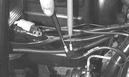
1.On the multimeter, place the switch in the DC Volts position; then connect the black tester lead to a suitable ground and the red tester lead to the fuel solenoid terminal.
DE647B
2.With the engine stop switch in the RUN position, turn the ignition switch to the ON position. The meter should read battery voltage and an audible
“click” should be heard from the fuel solenoid.
3.If no voltage is present, check the 15 amp ignition fuse, the ignition switch, or system wiring. If voltage is present, replace the fuel solenoid (see Fuel/Lubrication/Cooling).
Troubleshooting
Problem: Charging unstable Condition Remedy
1. Battery connections loose or corroded 1.Clean and tighten connections 2. Alternator belt loose 2.Tighten - replace belt 3. Alternator/regulator failing 3.Replace alternator assembly
Problem: Starter button not effective Condition Remedy
1. Battery charge low 1.Charge - replace battery 2. Switch contacts defective 2.Replace switch 3. Starter solenoid defective 3.Replace starter assembly 4. Starter relay defective 4.Replace relay 5. Emergency stop - ignition switch off 5.Turn on switches 6. Wiring connections loose - disconnected 6.Connect - tighten - repair connections
Problem: Battery discharges too rapidly Condition Remedy
1. Battery sulfided 1.Replace battery 2. Electrical system excessively loaded 2.Reduce load 3. Charging system not charging 3.Replace alternator - tighten alternator belt
Problem: Battery polarity reversed Condition Remedy
1. Battery incorrectly connected 1.Reverse connections - replace battery - repair damage