10 minute read
Suspension

The following suspension system components should be inspected periodically to ensure proper operation. A.Shock absorber rods not bent, pitted, or damaged. B.Rubber damper not cracked, broken, or missing. C.Shock absorber body not damaged, punctured, or leaking. D.Shock absorber eyelets not broken, bent, or cracked. E.Shock absorber eyelet bushings not worn, deteriorated, cracked, or missing.
F.Shock absorber spring not broken or sagging.
Shock Absorbers
REMOVING 1.Secure the ATV on a support stand to elevate the wheels and to release load on the suspension.
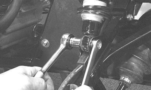
2.Remove the two cap screws and nuts securing each front shock absorber to the frame and the upper Aarm. Account for bushings and sleeves from each.
! WARNING
Make sure the ATV is solidly supported on the support stand to avoid injury.
AF605D
CAUTION
Additional support stands are necessary to support the rear axle when the shock absorbers are removed or damage may occur.
3.Remove the two cap screws and nut securing each rear shock absorber to the frame and lower A-arm.
Account for bushings and sleeves from each.
AF626D
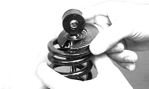
4.Compress the shock absorber spring, remove the retainer, and remove the spring.
AF730D
CLEANING AND INSPECTING
NOTE: Whenever a part is worn excessively, cracked,
or damaged in any way, replacement is necessary.
1.Thoroughly clean all shock absorber components. 2.Inspect each shock rod for nicks, pits, rust, bends, and oily residue. 3.Inspect all springs, spring retainers, shock rods, sleeves, bushings, shock bodies, and eyelets for cracks, leaks, and bends. INSTALLING 1.Place the shock absorber spring over the shock absorber, compress the spring, and install the retainer.
2.Place bushings and sleeves (where appropriate) into shock eyelet; then install shock with two cap screws and nuts. Tighten all front and upper rear nuts to 50 ft-lb and the lower rear A-arm nuts to 20 ft-lb.
3.Remove the ATV from the support stand.
CAUTION
Do not tighten the lower shock to A-arm nuts beyond the 20 ft-lb specification or the shock eyelet or mount WILL be damaged.
Front A-Arms
REMOVING 1.Secure the ATV on a support stand to elevate the front wheels; then remove the wheels.
2.Remove the cotter pin from the nut. Discard the cotter pin. ! WARNING
Make sure the ATV is solidly supported on the support stand to avoid injury.
CD008
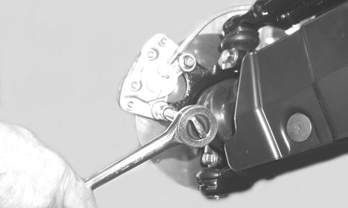
3.Remove the nut securing the hub. 4.Remove the brake caliper.
CD007
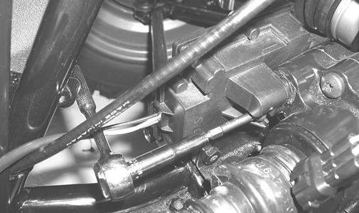
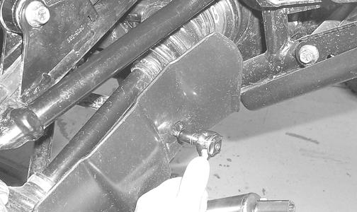
5.Remove the hub assembly. 6.Remove the cotter pin and slotted nut securing the tie rod end to the knuckle; then remove the tie rod end from the knuckle.
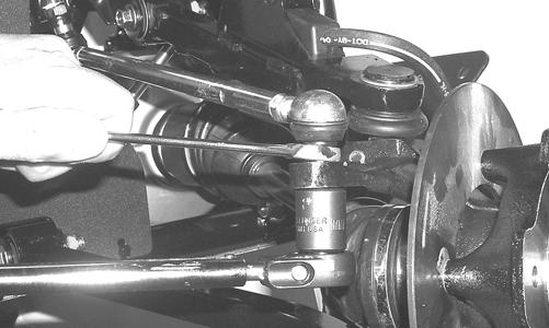
AF618D
7.Remove the cap screws securing the ball joints to the knuckle.
CAUTION
Support the knuckle when removing the cap screws or damage to the threads will occur.
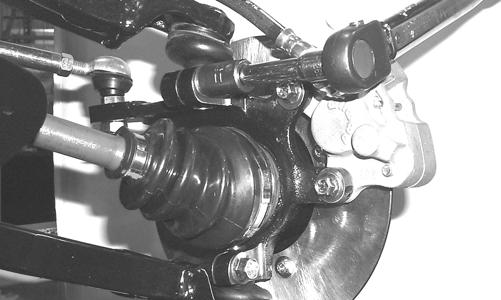
AF628D
8.Tap the ball joints out of the knuckle; then remove the knuckle.
9.Remove the lower shock absorber eyelet from the upper A-arm. 10.Remove the cap screws securing the A-arms to the frame.
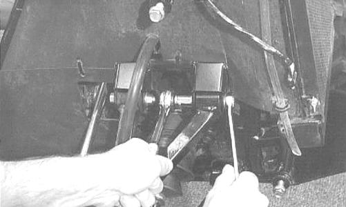
AF610D
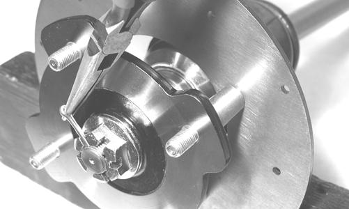
11.Remove the snap ring from the ball joint; then remove the ball joint from the A-arm.
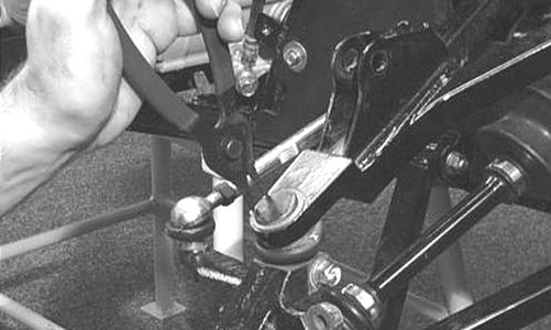
AF616D
CLEANING AND INSPECTING
NOTE: Whenever a part is worn excessively,
cracked, or damaged in any way, replacement is necessary.
1.Thoroughly clean all A-arm components using a pressure washer. 2.Clean the ball joint mounting hole of all residual
Loctite, grease, oil, or dirt for installing purposes. 3.Inspect the A-arm for bends, cracks, and worn bushings. 4.Inspect the ball joint mounting holes for cracks or damage. 5.Inspect the frame mounts for signs of damage, wear, or weldment damage. INSTALLING 1.Apply green Loctite #609 to the entire outside diameter of the ball joint; then install the ball joint into the
A-arm and secure with the snap ring.
AF616D
2.Install the A-arm assemblies into the frame mounts and secure with the cap screws. Only finger-tighten at this time.
AF610D
3.Route the brake hose through the upper A-arm shock absorber mount; then secure the hose to the A-arm with the routing clamp.
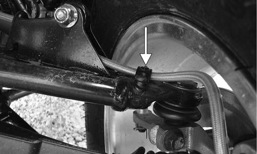
DE679A
4.Secure the lower eyelet of the shock absorber to the upper A-arm. Tighten nut to 50 ft-lb. 5.Secure the A-arm assemblies to the frame mounts (from step 2). Tighten the cap screws to 50 ft-lb 6.Install the knuckle assembly onto the ball joints and secure with cap screws. Tighten to 35 ft-lb.
AF628D
7.Install the tie rod end and secure with the nut.
Tighten to 35 ft-lb; then install a new cotter pin and spread the pin to secure the nut. NOTE: During assembly, new cotter pins should be
installed.
AF618D
8.Apply grease to the hub and drive axle splines; then install the hub assembly onto the drive axle.
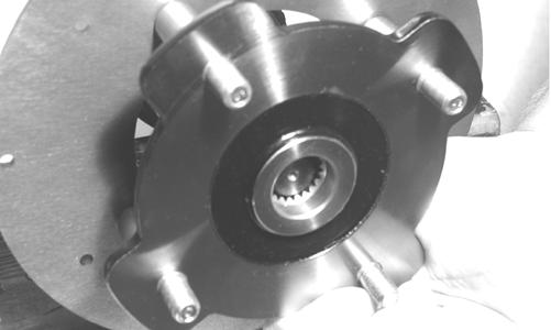
CD009
9.Secure the hub assembly with the nut. Tighten only until snug. 10.Secure the brake caliper to the knuckle with new
“patch-lock” cap screws. Tighten to 20 ft-lb.
CD007
11.Tighten the hub nut (from step 9) to 200 ft-lb. 12.Install a new cotter pin and spread the pin to secure the nut.
CD008
13.Install the wheel and tighten to 45 ft-lb (steel wheels) or 80 ft-lb (aluminum wheels). 14.Remove the ATV from the support stand.
Rear A-Arms
REMOVING 1.Secure the ATV on a support stand to elevate the wheels.
2.Pump up the hand brake; then engage the brake lever lock.
3.Remove the wheel.
4.Remove the cotter pin securing the hex nut; then remove the hex nut. Release the brake lever lock.
! WARNING
Make sure the ATV is solidly supported on the support stand to avoid injury.
5.Remove the caliper (right side only). NOTE: Do not allow the brake calipers to hang from
their cable/hose.
6.Remove the cap screws and lock nut securing the shock absorber to the frame and lower A-arm; then remove the shock absorber.
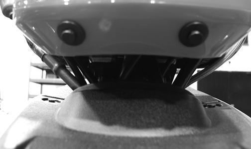
7.Remove the cap screws securing the boot guard to the lower A-arm.
AF934
NOTE: Never reuse a lock nut. Once a lock nut has
been removed, it must be replaced with a new lock nut.
10.Remove the cap screws and lock nuts securing the Aarms to the frame; then remove the A-arms. NOTE: If removing the upper right A-arm, it will be
necessary to disconnect the brake hose from the Aarm.
CLEANING AND INSPECTING
NOTE: Whenever a part is worn excessively,
cracked, or damaged in any way, replacement is necessary.
1.Thoroughly clean all A-arm components using a pressure washer. 2.Inspect the A-arm for bends, cracks, and worn bushings. 3.Inspect the frame mounts for signs of damage, wear, or weldment damage. INSTALLING 1.Install the A-arm assemblies into the frame mounts and secure with the cap screws and new lock nuts.
Only finger-tighten at this time. 2.Slide the knuckle onto the drive axle and into position on the A-arms; then secure the knuckle to the Aarms with cap screws and new lock nuts. Tighten to 50 ft-lb.
3.Tighten the hardware securing the A-arms to the frame mounts (from step 1) to 50 ft-lb. 4.Apply grease on the drive axle splines; then install the hub assembly onto the drive axle.
CD009
5.Secure the hub assembly with the nut. Tighten only until snug. 6.Secure the brake caliper to the knuckle with new
“patch-lock” cap screws (right side only). Tighten the caliper to 20 ft-lb. NOTE: Ensure that the brake hose is properly
routed and secured to the upper A-arm with the brake hose clips.

DE680A
7.Compress the hand brake lever and engage the brake lever lock; then secure the hub nut (from step 5) to the drive axle. Tighten to 200 ft-lb. 8.Install a new cotter pin and spread the pin to secure the nut.
CD008
9.Secure the shock absorber to the frame with a cap screw and new lock nut. Tighten to 50 ft-lb. 10.Secure the shock absorber to the lower A-arm with a cap screw and new lock nut. Tighten to 20 ft-lb. 11.Secure the boot guard to the lower A-arm with the two cap screws. Tighten securely. 12.Install the wheel and tighten to 45 ft-lb (steel wheels) or 80 ft-lb (aluminum wheels). 13.Remove the ATV from the support stand.
Wheels and Tires
TIRE SIZE
! WARNING
Use only Arctic Cat approved tires when replacing tires. Failure to do so could result in unstable ATV operation.
The ATV is equipped with low-pressure tubeless tires of the size and type listed in the General Information section. Do not under any circumstances substitute tires of a different type or size.
Do not mix tire tread patterns. Use the same pattern type on front and rear. Failure to heed warning could cause poor handling qualities of the ATV and could cause excessive drive train damage not covered by warranty.
TIRE INFLATION PRESSURE Front and rear tire inflation pressure should be 0.35 kg/ cm² (5.0 psi). REMOVING 1.Secure the ATV on a support stand to elevate the wheels.
2.Remove the wheels.
! WARNING
Make sure the ATV is solidly supported on the support stand to avoid injury.
NOTE: Keep left-side and right-side wheels sepa-
rated for installing them on their proper sides.
CLEANING AND INSPECTING
NOTE: Whenever a part is worn excessively, cracked,
or damaged in any way, replacement is necessary.
1.Thoroughly clean the wheels and hubs using a pressure washer.
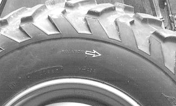
2.Clean the tires with soap and water. 3.Inspect each wheel for cracks, dents, or bends. 4.Inspect each tire for cuts, wear, missing lugs, and leaks. INSTALLING Install each wheel on its hub. Tighten to 45 ft-lb (steel wheels) or 80 ft-lb (aluminum wheels). NOTE: Make sure each wheel is installed on its
proper hub as noted in removing (the “rotation arrow” (if applicable) must indicate forward direction of rotation).
AF612D
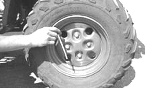
CHECKING/INFLATING 1.Using an air pressure gauge, measure the air pressure in each tire. Adjust the air pressure as necessary to meet the recommended inflation pressure.
CD005
2.Inspect the tires for damage, wear, or punctures.
! WARNING
Do not operate the ATV if tire damage exists.
NOTE: If repair is needed, follow the instructions
found on the tire repair kit or remove the wheel and have it repaired professionally.
NOTE: Be sure all tires are the specified size and
have identical tread pattern.
3.Check the front wheel toe-in and adjust as necessary (see Steering/Frame). 4.Test drive the ATV on a dry, level surface and note any pulling to the left or right during acceleration, deceleration, and braking. NOTE: If pulling is noted, measure the circumfer-
ence of the front and rear tires on the pulling side. Compare the measurements with the tires on the opposite side. If pulling is noted during braking only, check and adjust the brakes as necessary and recheck operation (see Periodic Maintenance/TuneUp).
5.Increase the air pressure in the tires with the smallest circumference measurement until all tires are equal in circumference.
6.Repeat steps 4-5 as necessary to ensure proper handling.
Troubleshooting
Problem: Suspension too soft Condition Remedy
1. Spring(s) weak 1.Replace spring(s) 2. Shock absorber damaged 2.Replace shock absorber 3. Shock absorber preload too low 3.Adjust shock absorber preload
Problem: Suspension too stiff Condition Remedy
1. A-arm-related bushings worn 1.Replace bushing 2. Shock absorber preload too high 2.Adjust shock absorber preload
Problem: Suspension noisy Condition Remedy
1. Cap screws (suspension system) loose 1.Tighten cap screws 2. A-arm-related bushings worn 2.Replace bushings