Suspension The following suspension system components should be inspected periodically to ensure proper operation. A. Shock absorber rods not bent, pitted, or damaged. B. Rubber damper not cracked, broken, or missing. C. Shock absorber body not damaged, punctured, or leaking. D. Shock absorber eyelets not broken, bent, or cracked. E. Shock absorber eyelet bushings not worn, deteriorated, cracked, or missing.
AF626D
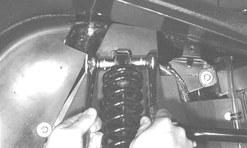
4. Compress the shock absorber spring, remove the retainer, and remove the spring.
F. Shock absorber spring not broken or sagging.
Shock Absorbers REMOVING 1. Secure the ATV on a support stand to elevate the wheels and to release load on the suspension.
! WARNING Make sure the ATV is solidly supported on the support stand to avoid injury.
2. Remove the two cap screws and nuts securing each front shock absorber to the frame and the upper Aarm. Account for bushings and sleeves from each.
AF730D
CLEANING AND INSPECTING NOTE: Whenever a part is worn excessively, cracked, or damaged in any way, replacement is necessary.
1. Thoroughly clean all shock absorber components. 2. Inspect each shock rod for nicks, pits, rust, bends, and oily residue. 3. Inspect all springs, spring retainers, shock rods, sleeves, bushings, shock bodies, and eyelets for cracks, leaks, and bends.
INSTALLING 1. Place the shock absorber spring over the shock absorber, compress the spring, and install the retainer. AF605D
CAUTION Additional support stands are necessary to support the rear axle when the shock absorbers are removed or damage may occur.
3. Remove the two cap screws and nut securing each rear shock absorber to the frame and lower A-arm. Account for bushings and sleeves from each.
2. Place bushings and sleeves (where appropriate) into shock eyelet; then install shock with two cap screws and nuts. Tighten all front and upper rear nuts to 50 ft-lb and the lower rear A-arm nuts to 20 ft-lb.
CAUTION Do not tighten the lower shock to A-arm nuts beyond the 20 ft-lb specification or the shock eyelet or mount WILL be damaged.
3. Remove the ATV from the support stand.
Manual Table of Contents
135