Manual
User
CONTENT I. General Description.................................................................................................................................1 1.1 Product Example 1 1.2 Home Installation Diagram 2 II. Set up Smart Life APP 3 2.1 Download APP Smart Life 3 2.2 Connect Panel to Smart Life APP .............................................................................................3 2.3 Settings on APP 7 III. Set up the Security Devices 9 3.1 Security Panel 9 3.2 Entry Sensor 12 3.3 Motion Sensor..........................................................................................................................14 3.4 Controller 15 3.5 Multifunction Button Doorbell/SOS Button 16 IV. Learn to Use the Security Panel 17 4.1 Main Interface 17 4.2 Menu introduction....................................................................................................................18 4.2.1 Accessory 18 4.2.2 Phone 19 4.2.3 Security 21 4.2.4 Settings 22 V. Troubleshooting and Maintenance ......................................................................................................23 VI. Hazardous Substance Declaration 24 VII. Warranty Rules 24 VIII. FCC Declares 25
General Description
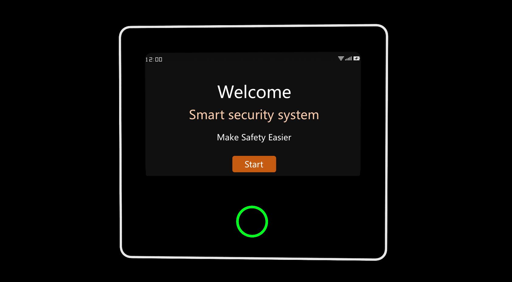
The central hub of the security system. Using 4.3 inch IPS capacitive touch screen, built in high performance low power intelligent microprocessor. With a variety of installation methods: wall mounted, desktop placement. Added built in siren, up to 110dB. It connects all of your accessories to the APP, so you can stay in control of your home from anywhere.
Accessories list: (Subject to actual packaging)
Entry Sensor ControllerMotion Sensor
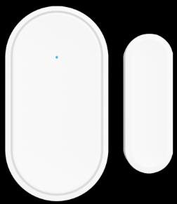
Send the alarm signal to the panel when the door or window are opened, it is recommended to install at important entrances.
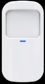
Send the alarm signal to the panel when the movement is detected.
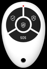
After pairing with the security panel, quickly "Away", "Home", and "Disarm" the security system, and trigger the emergency alarm.
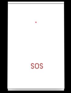
Multifunction Button
Doorbell button or SOS button
1 / 25 I.


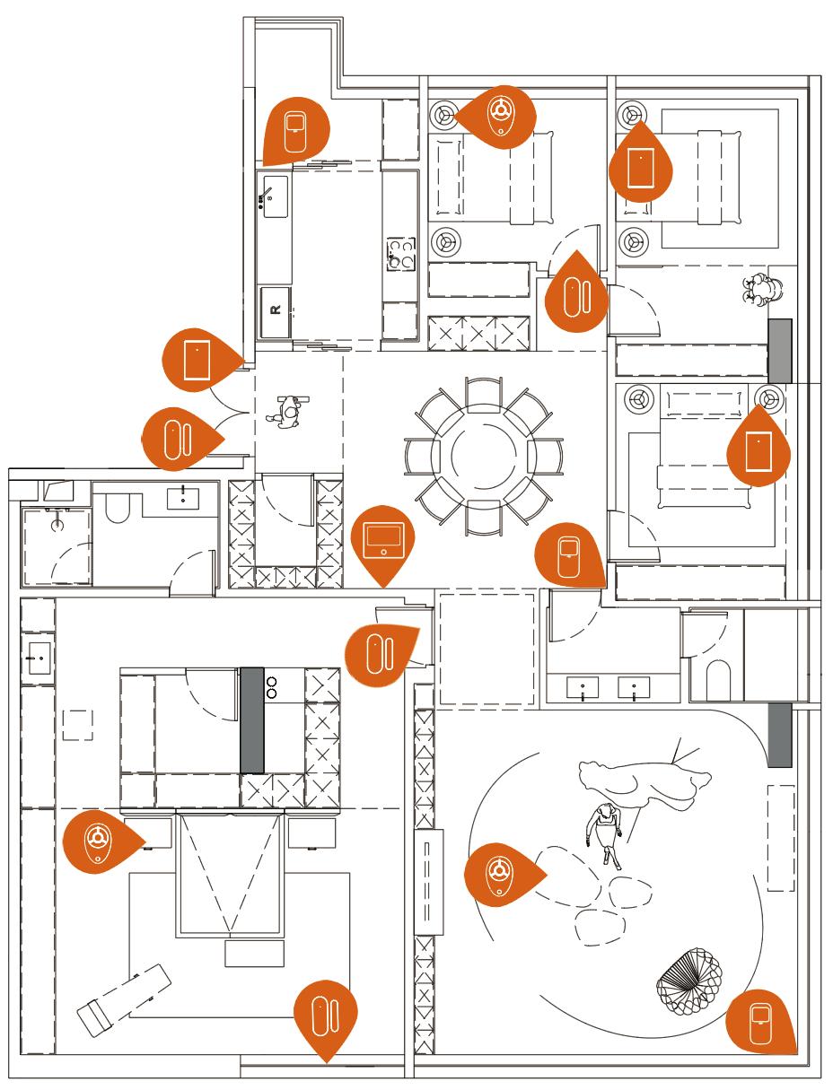

2 / 25 1.2 Home Installation Diagram Motion Sensor Doorbell Button ControllerSecurity Panel Entry Sensor SOS Button
II.
Set up Smart Life APP
2.1 Download APP Smart Life
Note:
Turn on the panel, choose a language, and scan the QR code on the panel to download; Users can also search "Smart Life" in major global APP stores or scan the QR code below to download.
(1) iOS users, please scan the Apple APP QR code.
(2) Android users, please scan the QR code of Google Play to download.

(3) After downloading the APP, please enable all usage permissions for the APP in the phone settings
(4) Sign up or Log in to your APP account.
2.2 Connect Panel to Smart Life APP
Note:
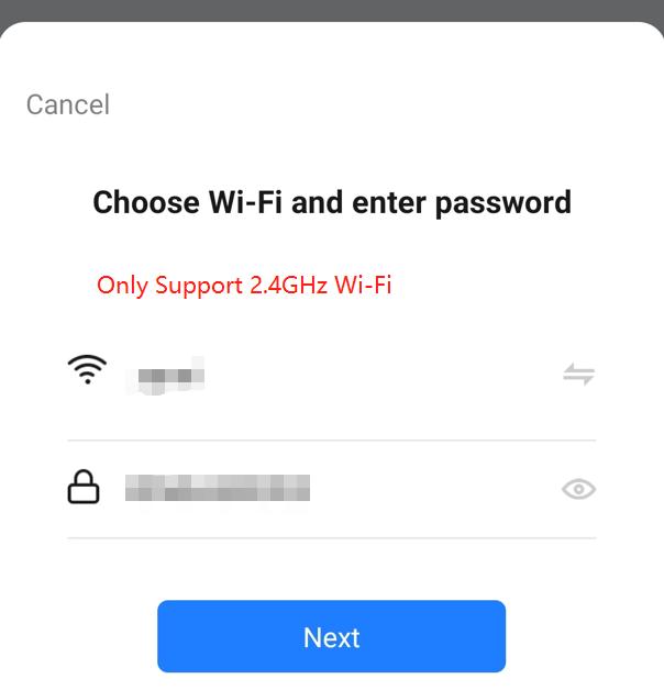
(1) This security panel only supports 2.4GHz WiFi networks only. Make sure your router is set up correctly and can connect to the Internet.
(2) When adding the security panel to the Smart Life APP, please turn on the mobile phone WiFi and Bluetooth, and confirm that the mobile phone is connected to the 2.4GHz frequency band.
3 / 25
Steps:
(1)
4 / 25
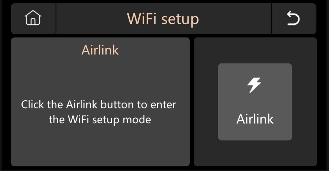
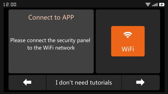
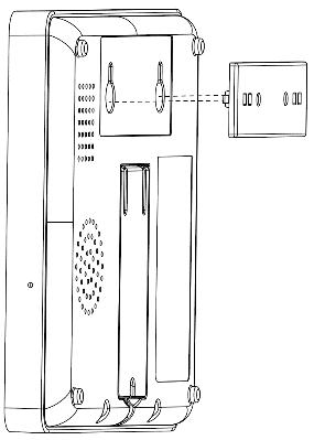
For first time use, please connect the security panel to the power supply, and turn the backup battery switch on the back of the panel to the “ON” position, then enter the operation guide interface If you have entered the main interface or want to reset the WiFi, please click "Menu" "Settings" "WiFi", and enter the default user code: 1234. Operation Guide Interface Press WiFi Icon (2) Press “Airlink” to enter the WiFi pairing mode.
(3)
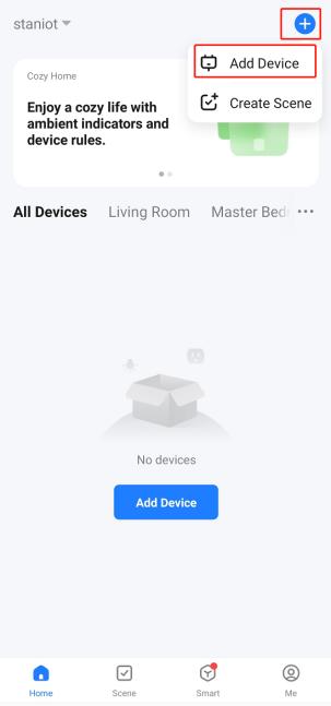
enter the "Home" interface.
A. Click the "+" on the upper right corner of the interface and select "Add Device".
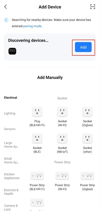
B. Press “Add” on the discovering device’s area
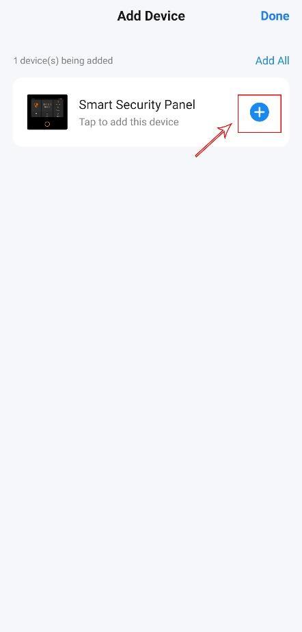
C. Press the “+” Smart Security Panel.
D. Input the 2.4Ghz WiFi name and password, and click "Next".
5 / 25
On the APP: Open the "Smart Life" APP and
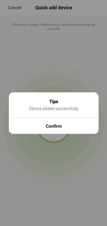
(4) When the device is successfully connected to the APP, the device will give a voice prompt of "Setup successful". The APP will also show that the device has been added successfully.
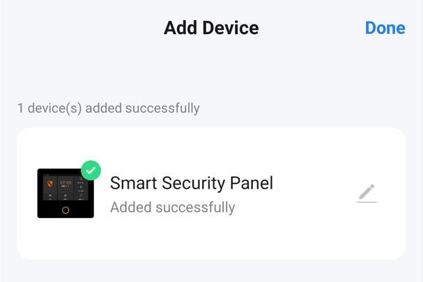
6 / 25 E. Paired successfully
2.3 Settings on APP
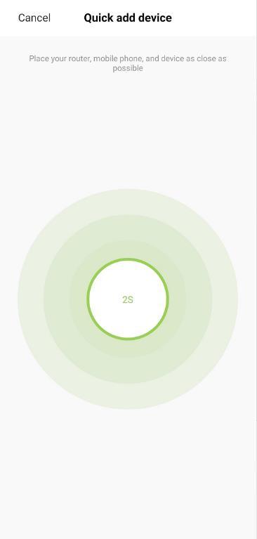
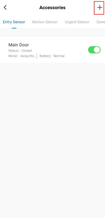
2.3.1 Add Device
Click Accessories, press “ + ”, and then trigger the accessory to complete the pairing.
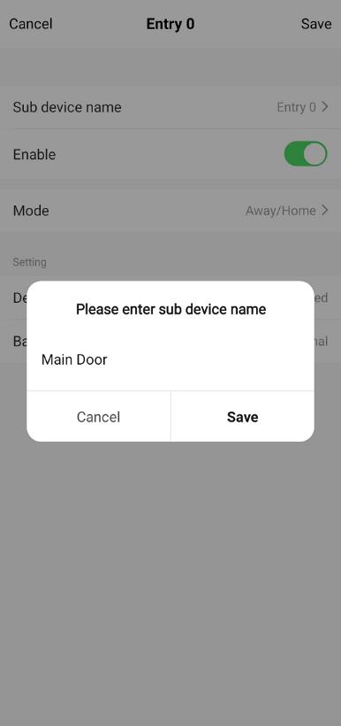
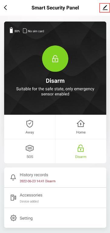
2.3.2 Rename Device
Accessory names can only be renamed on the APP, just press “Sub device name” to edit the name.
7 / 25
2.3.3 Share Device
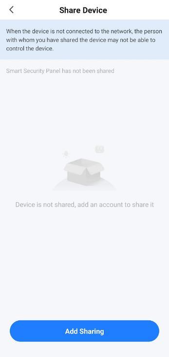
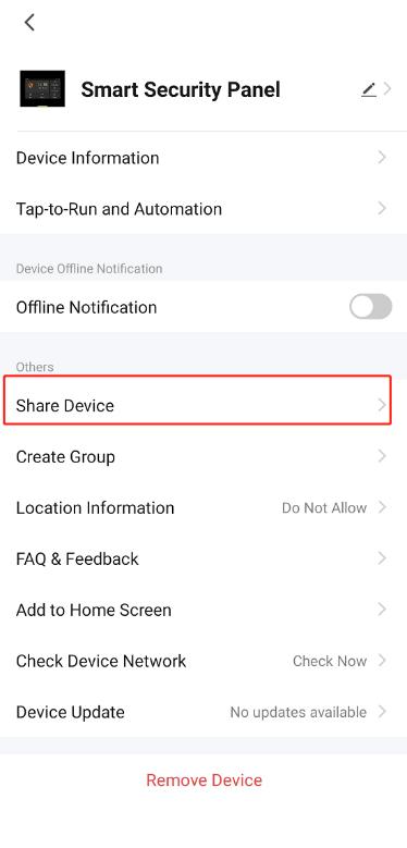
A security panel can only be paired with one APP account, but you can share it with multiple family members to manage together
2.3.4 Other Settings
Press Setting, and can directly modify the settings in the security panel on the APP
Through the APP, you can remotely control the security panel. You can also set the arm and disarm time, which is simple and convenient.
8 / 25
III. Set up the Security Devices
3.1 Security Panel
3.1.1 Installation Diagram
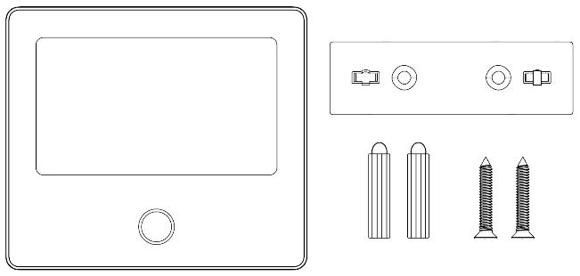
(1) Wall Mount
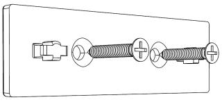
F
Security Panel×1 Wall Hanging Plate×1
Screws×2
1. Install the hanging plate on the wall with screws
Note: The screws must be all nailed to the wall, and the hanging board must be parallel.
2. Align the hole on the back of the panel with the hanging plate and install it
Note: For concealed wire installation, please remove the bracket and cable clip.
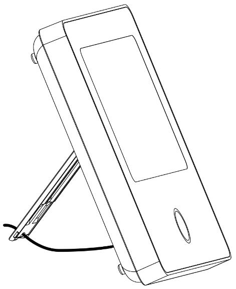
(2) Placed on the Desktop
Comes with a Stand on the Back
It can be directly placed on the desktop, free from the installation of holes on the wall, and can be placed anywhere in the home
Note:
1) Installed in the center of the home to facilitate signal reception and transmission.
2) Install it closer to the WiFi router.
3) Avoid installing all devices on metal surfaces, as well as on load bearing walls.
9 / 25
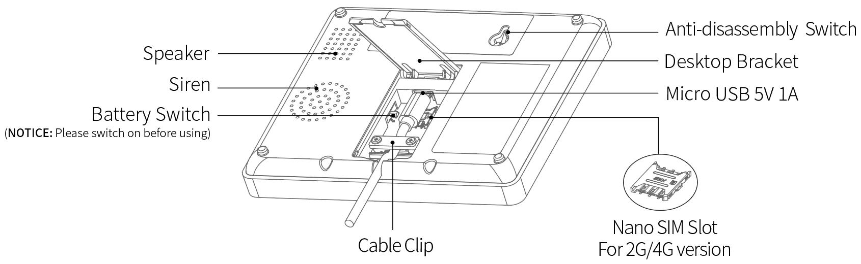
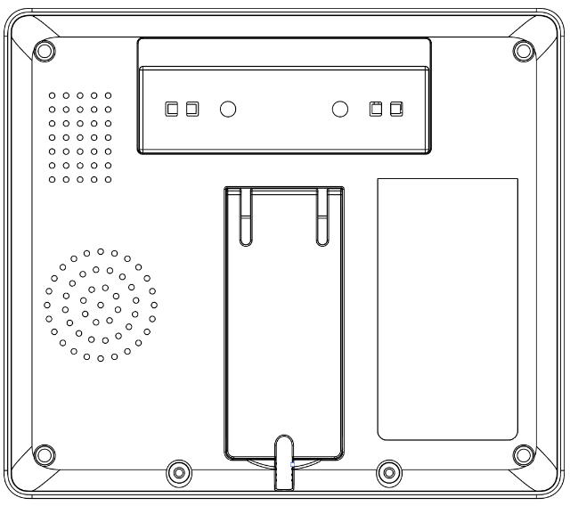
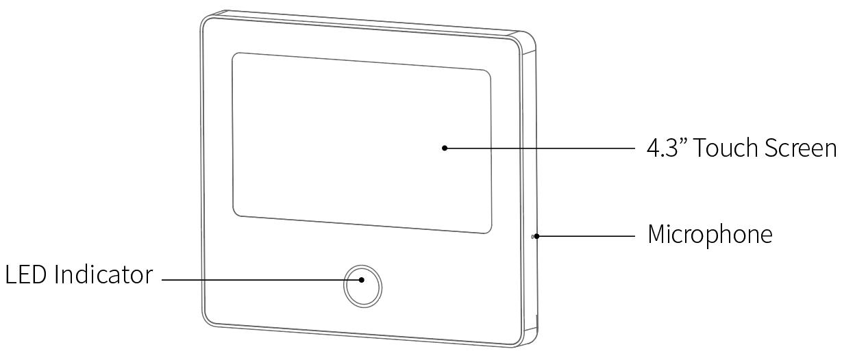
10 / 25 3.1.2 Appearance Design Front View Back View Rear Main View
3.1.4 Alarm Modes
A. Security Panel Alarm Modes
a. Away: The security panel is in a monitoring state, when the accessories are triggered, the security panel will alarm.
b. Home: When the user is at home, in this mode, some areas can be monitored and alarms.
c. Disarm: The security panel cancels the monitoring state, and only the SOS button or the accessories set to "Always" mode can trigger the alarm.
B. Accessories Modes
a. Away/Home When the security panel is in the "Away" or "Home" state, the panel will alarm after the sensor is triggered. It is recommended that the outdoor sensor can be set to this mode.
b. Away When the security panel is in the "Away" state, the panel will alarm after the sensor is triggered. It is recommended that the outdoor detector can be set to this mode.
c. Always Regardless of the state of the security panel, any time the sensor is triggered, the panel will alarm. It is recommended to set this mode for gas leaks or smoke detectors, etc.
d. Disabled The security panel will not respond to the alarm request of the sensor set in this mode.
Note:
You can choose which sensors are armed in Home and Away mode, or both, or always active.
For example, if you want to avoid triggering the alarm when you are at home, you can set the specific sensor in Away mode. Then when you set the panel in “Home” state, the alarm will not be triggered, only in “Away” state, the alarm will be triggered.
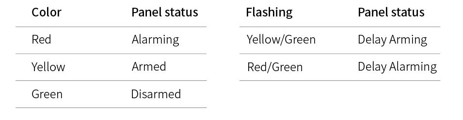
11 / 25 3.1.3 Indicator:
3.2 Entry Sensor
3.2.1 Configure
On the Security Panel:
A. Go to Menu Accessories Enter User Code (Default: 1234).
B. Press Sensor “+” Entry, then set the Mode, Delay, and Advanced settings.
C. Press “+ Pair”, then trigger the Entry sensor (Just separate the two parts)
D. Paired successfully, rename the sensors on the APP.
3.2.2 Installation
The entry sensor should be installed on the door or window (see image).
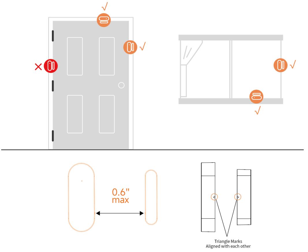
A. First, wipe the area on the door or window clean and apply double sided tape to the bottom.
B. The door sensor transmitter (large) and the door sensor magnet (small) should be installed separately. The triangle marks on the transmitter and the magnet should be facing each other, and the distance between the two is less than 0.6”
C. When the door or window is opened after installation, the indicator light will be on for 2 seconds to indicate that the installation is complete.
12 / 25
Door Sensor A
Battery specification: CR2032×1
Door Sensor B
Battery specification: CR2032×1
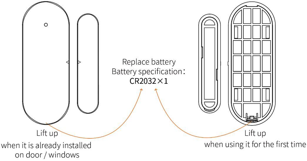
13 / 25 3.2.3 Battery Replacement
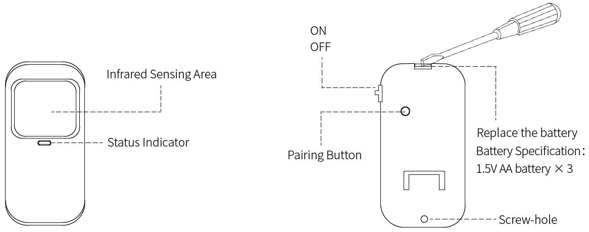
3.3 Motion Sensor
3.3.1 Configure
On the Security Panel:
A. Go to Menu Accessories Enter User Code (Default: 1234).
B. Press Sensor “+” Motion, then set the Mode, Delay, and Advanced settings.
C. Press “+ Pair”, then trigger the Motion sensor (Just wave your hands until the light is on).
D. Paired successfully, rename the sensors on the APP.
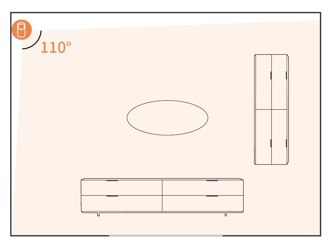
3.3.2 Installation
A. The recommended installation height is 79” 87” (2.0~2.2m) above the ground
B. Install it in a corner or on a flat wall, with no obstacles or blind spots.
C. It should not be directly facing the cold and hot vents or cold and hot sources
D. To avoid false alarms, make sure your pets can’t get close to it.
14 / 25
3.4 Controller
3.4.1 Configure
On
A.
Steps:
3.4.2
15 / 25
the Security Panel:
Go to Menu Accessories Enter User Code (Default: 1234). B. Press Controller C. Press “ + ”, then trigger the controller (Press any key). D. Paired successfully, rename the controller on the APP
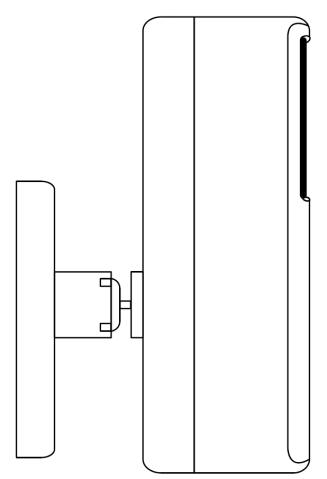
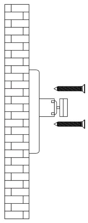
Appearance Introduction
1) Screw the base to the wall 2) Hang the motion sensor on the rotating shaft
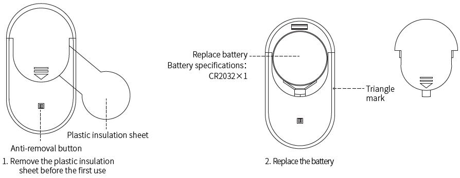
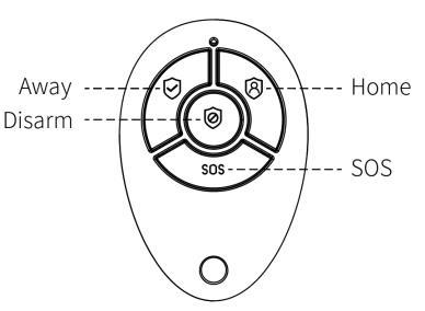
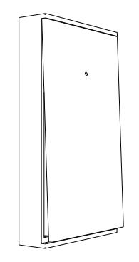
3.5 Multifunction Button Doorbell/SOS Button
3.5.1 Configure Doorbell Button
On the Security Panel:
A. Go to Menu Accessories Enter User Code (Default: 1234).
B. Press Doorbell
C. Press “+”, then press the doorbell button.
D. Paired successfully, rename the sensors on the APP.
3.5.2 Configure SOS Button
On the Security Panel:
A. Go to Menu Accessories Enter User Code (Default: 1234).
B. Press Sensor “+” Urgent, then set the Advanced setting.
C. Press “+ Pair”, then trigger the SOS button.
D. Paired successfully, rename the SOS button on the APP.
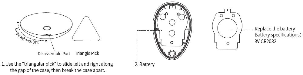
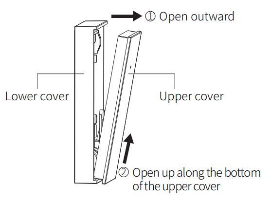
3.5.3 Install/Replace Battery
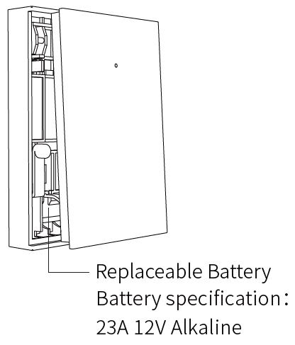
a. Open the cover:
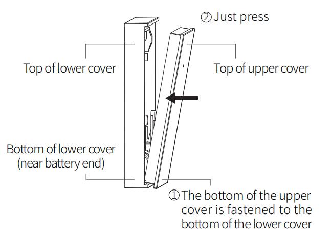
b. Close the cover:
16 / 25
Learn to Use the Security Panel


17 / 25 IV.
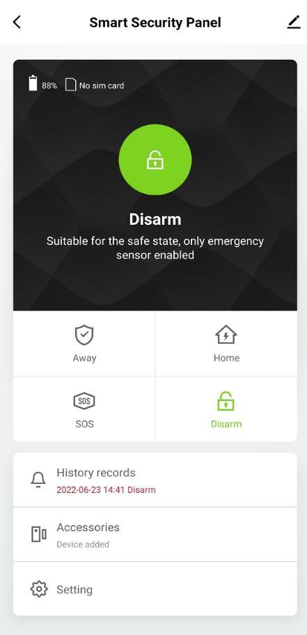
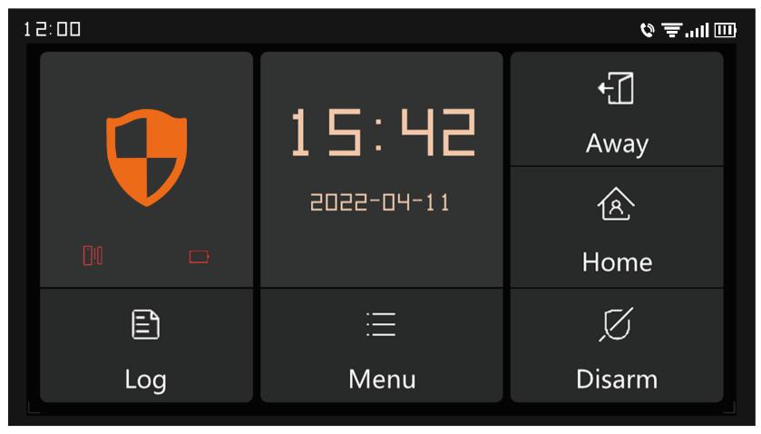
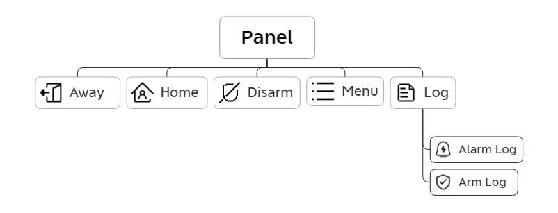
4.1 Main Interface 4.1.1 System Status Icon Status The system is in alarm state System is armed System is disarmed Accessories low battery Door/Window opened 4.1.2 Log Alarm Log: View all alarm records, including Cause, Source, and Time Arm Log: View all arm/disarm records, including Action, Source Device, and Time Note: Support up to 160 Alarm records, and 80 Arm and disarm records.
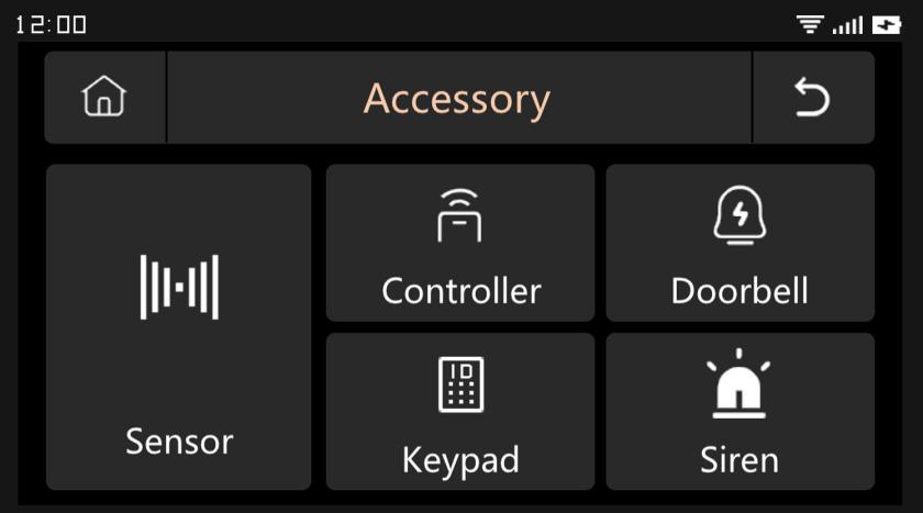
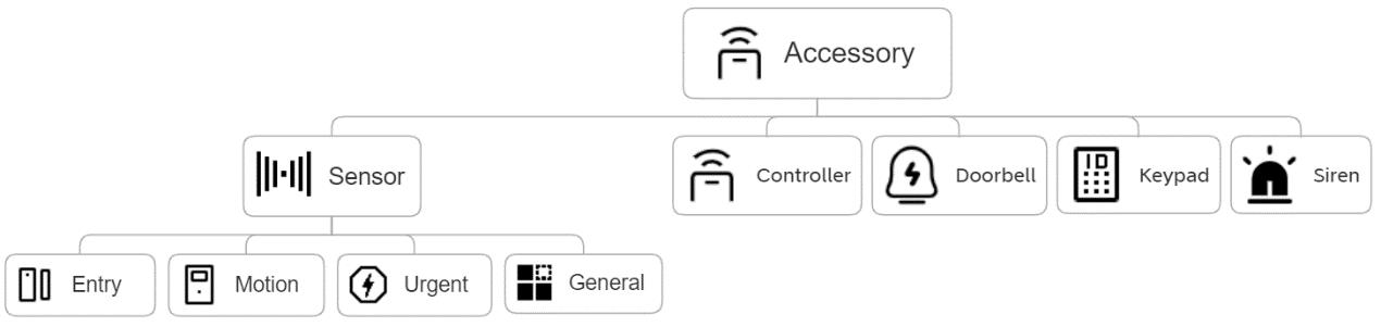
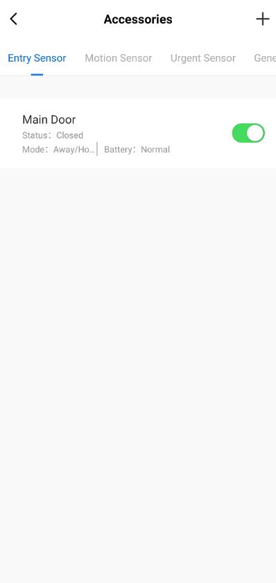
18 / 25 4.2 Menu introduction 4.2.1 Accessory A. Frame Diagram B. Sensor Entry: Manage all the Entry sensors. Motion: Manage all the Motion sensors Urgent: Emergency detectors such as SOS buttons, gas detectors, and smoke detectors, please add them here General: Other sensors or detectors, please add them here Note: 1) The security system supports the accessories with 433MHz, ev1527. 2) For the Entry sensors from another brand, please add it to “General” 3) Support up to 160 Sensors, 6 Controllers, 6 Doorbells, 6 Keypads.
Please
1)
2)
Setup Example
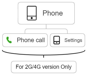
the call will start from the first
times in a row and no answer, the second phone number will be dialed, and so on. If one of the phone numbers is answered, subsequent
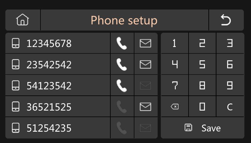
When the first number
numbers will not be dialed.
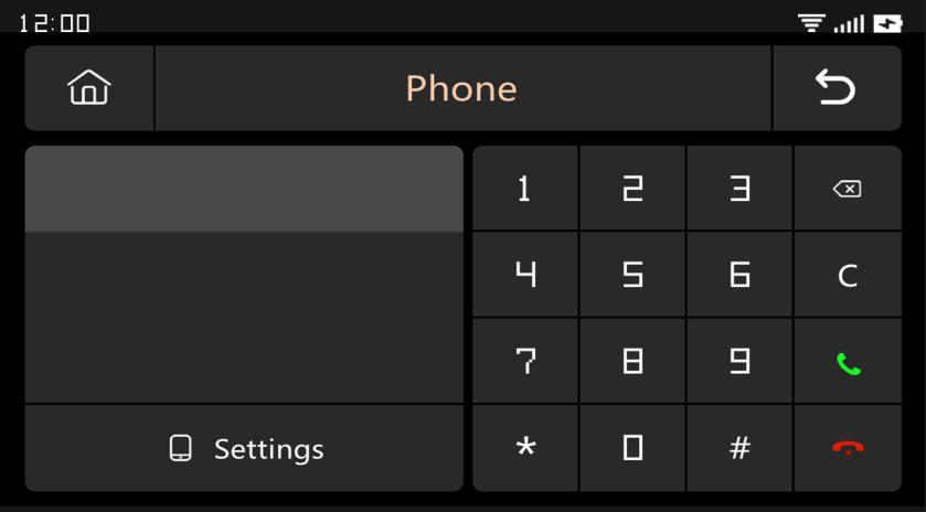
19 / 25 4.2.2 Phone (1) Frame Diagram (2) Emergency Number
light up the corresponding Phone/SMS icon according to your needs
Phone Number Format: If the phone number cannot be successfully dialed or sent a text message, please try adding the area code before the number: For example: 00XX, 0XX
SMS/Phone Alarm Rules: After the alarm is triggered, the security panel will firstly send SMS messages in the order of the set numbers. After the text message is sent,
phone number.
is dialed three
phone
(3) Arm/Disarm Panel by SMS Command. (Firmware version should be 1.0.20 or above)
The SMS commands and panel actions were taken are as below:
No. SMS Command Action Taken by the Panel Replied SMS
1 away arm The panel will be in “Away” mode System armed!
2 stay arm The panel will be in “Home” mode System armed!
3 disarm The panel will be in “Disarm” mode System disarmed!
The panel will reply message to confirm the command is executed successfully.
NOTE: The panel only accepts SMS commands from the phone number set in the panel. (Menu >Phone >Settings), the SMS commands sent by other mobile numbers will be not recognized and no action will be taken.
20 / 25
4.2.3 Security
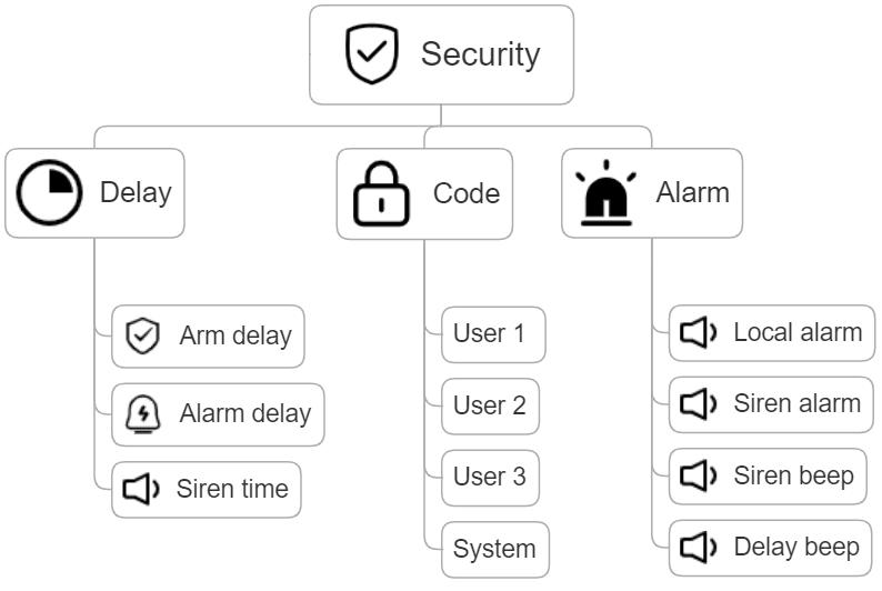
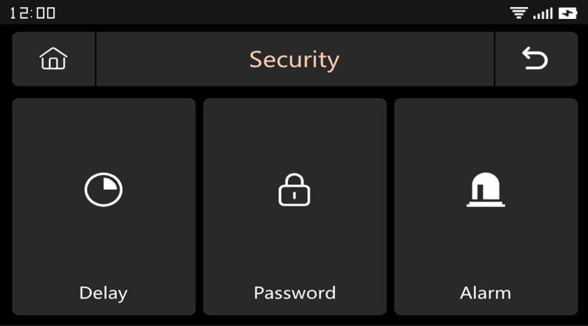
(1) Frame Diagram
(2) Delay: Customize the countdown time when Alarm or Arm.
(3) Code:
1) User Code: Default user code is 1234.
2) System Code: Default system code is 9876.
3) Obfuscated Code: When entering the code, you can enter 5 to 8 digits of the obfuscated code, as long as it contains the correct 4 digits in succession, it can be recognized as the correct code.
4) Password Validity Period: After selecting, you do not need to enter the password again within 2 minutes when the screen is on.
(4) Alarm:
Local Alarm: Select whether the panel emits an alarm sound
Siren Alarm: Select whether the external signal emits an alarm sound
Siren Beep: Select whether the siren will beep when Arm/Disarm the panel.
Delay Beep: Choose whether to sound a beep when Arm or Alarm countdown.
21 / 25
(2)
(3)
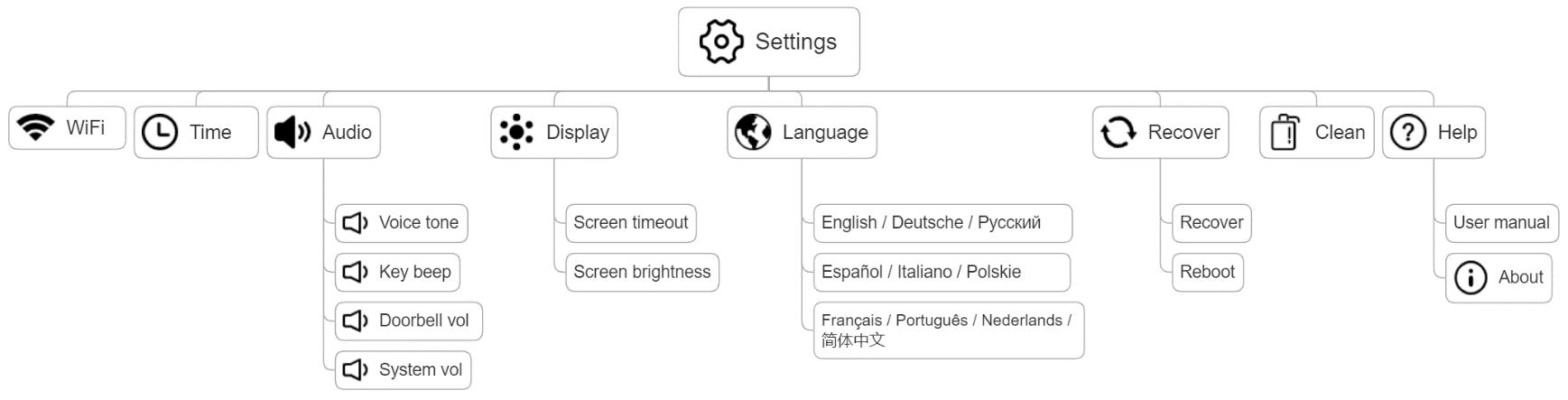
Settings
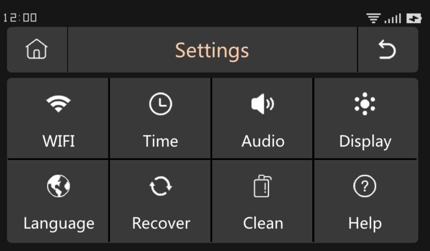
Frame Diagram
(8)
22 / 25 4.2.4
(1)
WiFi: Connect the APP to configure the network or change the APP user.
Time: Set the time and adjust the date display format (4) Audio: Adjust volume, turn on/off Key beep, Voice tone (5) Display: Set screen time and brightness (6) Language: English / Deutsche / P / Español / Italiano Polskie/ Français / Portugu s / Nederlands / (7) Recover: Restart or reset the device.
Clean: The screen will be black for 1 minute, easy to clean the screen (9) Help: User Manual, Device parameter information: Model, Version, IMEI, etc.
V. Troubleshooting and Maintenance
Failure The Reason The Solution
1. Low battery
Remote control malfunction
2. The metal sheet of the battery compartment is in poor contact or is corroded
3. The code is not paired with the panel
4. Does not match the wireless parameters of the panel
1. Low battery
2. The metal sheet of the battery compartment is in poor contact or is corroded
1. Replace the battery of the same model
2. Remove rust and dirt from metal sheets
3. Re pair with the panel
4. Purchase accessories of the same type with technical parameters
1. Replace the battery of the same model
2. Remove rust and dirt from metal sheets
3. Re pair with the panel
Door sensor failure
3. The code is not paired with the panel
4. Does not match the wireless parameters of the panel
5. The door sensor transmitter and the magnet are installed too far
1. Low battery
2. The metal sheet of the battery compartment is in poor contact or is corroded
4. Purchase accessories of the same type with technical parameters
5. Install the door sensor transmitter and the magnet close to each other
1. Replace the battery of the same model
2. Remove rust and dirt from metal sheets
Motion Detector failure
3. The code is not paired with the panel
4. Does not match the wireless parameters of the panel
5. Incorrect angle
1. The security panel is not armed
Security panel does not alarm
The signal distance of the panel receiving accessories becomes shorter
2. Improper installation of accessories, too far away from the panel
3. The accessory code does not match the panel
3. Re pair with the panel
4. Purchase accessories of the same type with technical parameters
5. Adjust the installation angle
1. Arming the panel
2. Adjust the position of accessories
3. Re pair with the panel
1. The main power is disconnected, and the backup power is insufficient
2. There is interference from similar products nearby
3. The panel receiving module is faulty
1. Check the power supply and restore the power supply
2. Check the source of interference and remove it
3. Contact customer service for repair
23 / 25
1.
VI. Hazardous Substance Declaration
Contact
service
Component Name
VII. Warranty Rules
Harmful substance
Hexavalent
Polybrominated biphenyls PBB
Polybrominated diphenyl
PBDE
24 / 25 No emergency call was made when the alarm was triggered 1. The panel is not armed 2. No emergency phone number is set 3. Improper installation of accessories, too far away from the panel 4. Encoding does not match
Arming the panel 2. Re set according to the instructions 3. Adjust the position of accessories 4. Re pair with the panel WiFi network configuration failed 1. 2.4GHz WiFi is not connected 2. The current router is not compatible with quick configuration 3. Damaged WiFi module 1. Connect to 2.4GHz WiFi 2. Adopt panel WiFi hotspot configuration mode 3.
customer
for repair Entry opened warning is invalid 1. Door sensor pairing error 2. The door sensor switch code does not match the panel 3. Wrong alarm type is set 1. The door opening code needs to be paired correctly 2. The accessories are non certified devices 3. Set the alarm type as main door alarm and window alarm
(1) Please contact our after sales service for any failure caused by the product itself during the warranty period. (2) The goods are guaranteed for one year from the date of sale, and the warranty service is only valid under normal use. (3) Damage caused by the use environment not meeting the requirements of this product is not covered by the warranty. (4) Product damage caused by man made and force majeure is not covered by the warranty.
Lead Pb Mercury Hg Cadmium Cd
chromium Cr(VI)
ethers
Metal parts O O O O O O Plastic parts O O O O O O
VIII. FCC Declares
This device complies with Part 15 of the FCC Rules.
Operation is subject to the following two conditions: (1) this device may not cause harmful interference, and (2) this device must accept any interference received, including interference that may cause undesired operation

NOTE: This equipment has been tested and found to comply with the limits for a Class B digital device, pursuant to Part 15 of the FCC Rules. These limits are designed to provide reasonable protection against harmful interference in a residential installation. This equipment generates, uses and can radiate radio frequency energy and, if not installed and used in accordance with the instructions, may cause harmful interference to radio communications. However, there is no guarantee that interference will not occur in a particular installation. If this equipment does cause harmful interference to radio or television reception, which can be determined by turning the equipment off and on, the user is encouraged to try to correct the interference by one or more of the following measures:
Reorient or relocate the receiving antenna.
Increase the separation between the equipment and receiver.
Connect the equipment into an outlet on a circuit different from that to which the receiver is connected.
Consult the dealer or an experienced radio/TV technician for help. Warning: changes or modifications not expressly approved by the party responsible for compliance could void the user's authority to operate the equipment
25 / 25