5 - Installation
Connections to the communication and control board 20
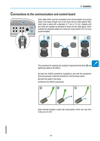
Each cable which must be connected to the communication and control board must pass through one of the three service cable glands M20, which take a cable with a diameter of 7 mm to 13 mm. Gaskets with two holes are supplied as standard to insert into the cable gland, which enables two separate cables of a maximum cross-section of 5 mm to be accommodated.
A
B
The procedure for opening the contacts of signal terminal block tightening cables is as follows:
C
13
and
a) Insert the WAGO screwdriver (supplied) in slot with the screwdriver facing downwards; insert the screwdriver until the clamp opens. b) Insert the cable in the clamp. c) Remove the WAGO screwdriver. a
b
c
000426BG
Each terminal accepts a cable with cross-section which can vary from 0.08 up to 2.5 mm².
- 55 -


