Reasons to choose Omnia L
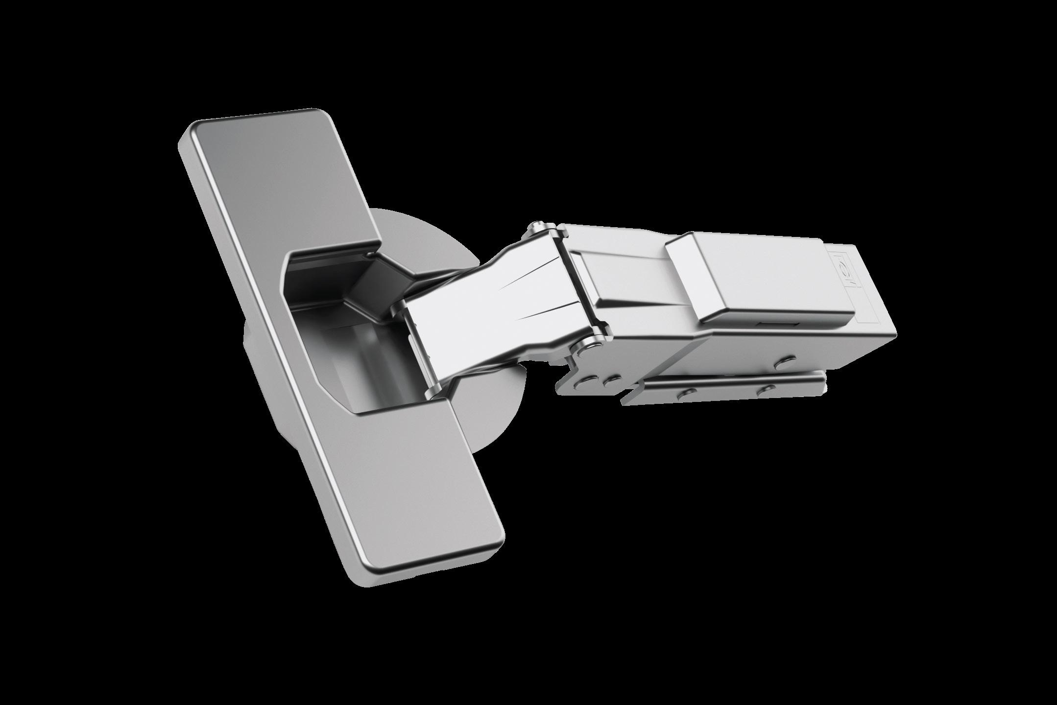
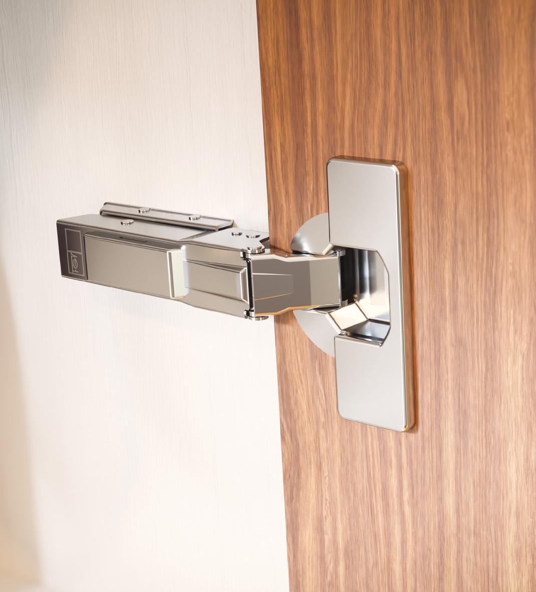
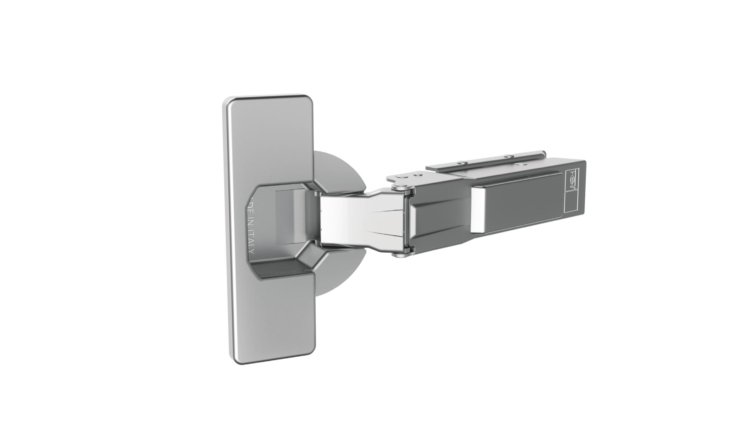
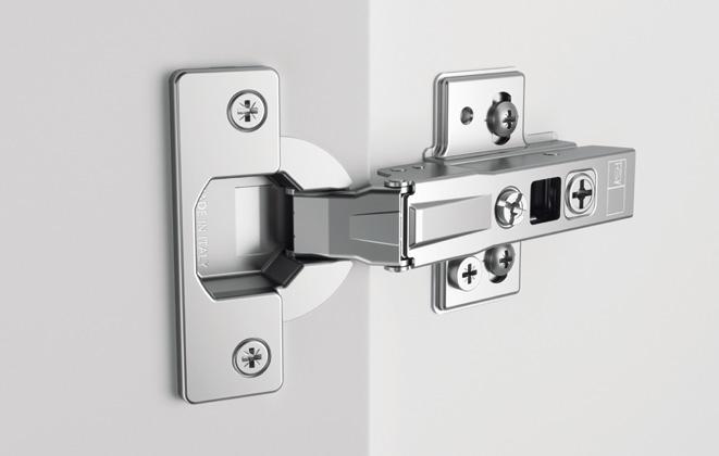
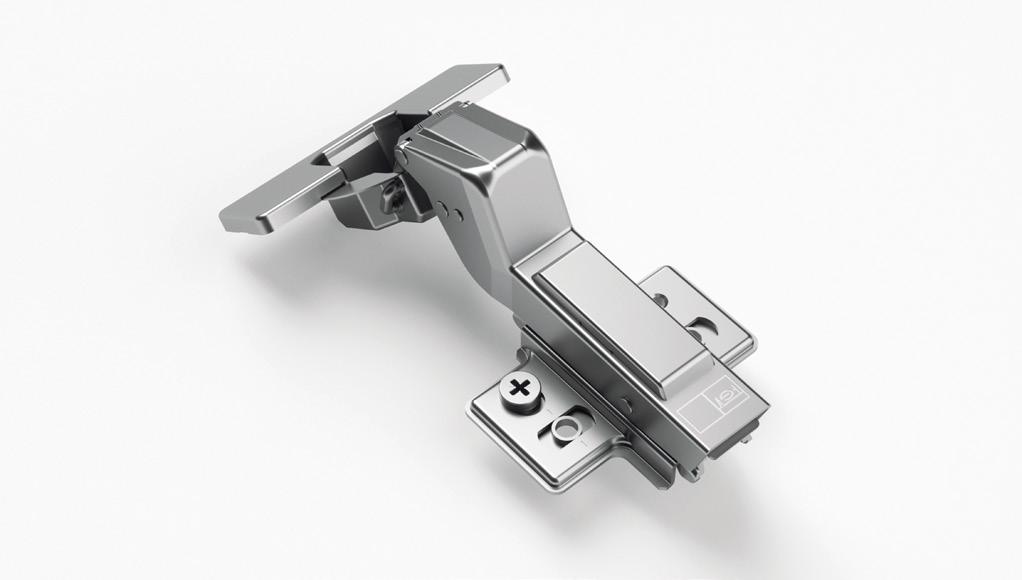
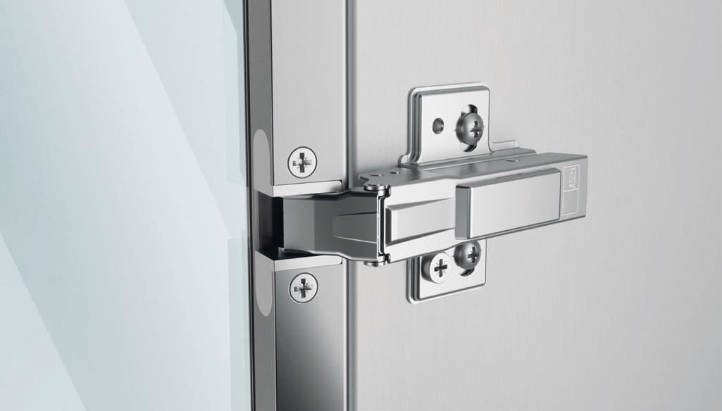
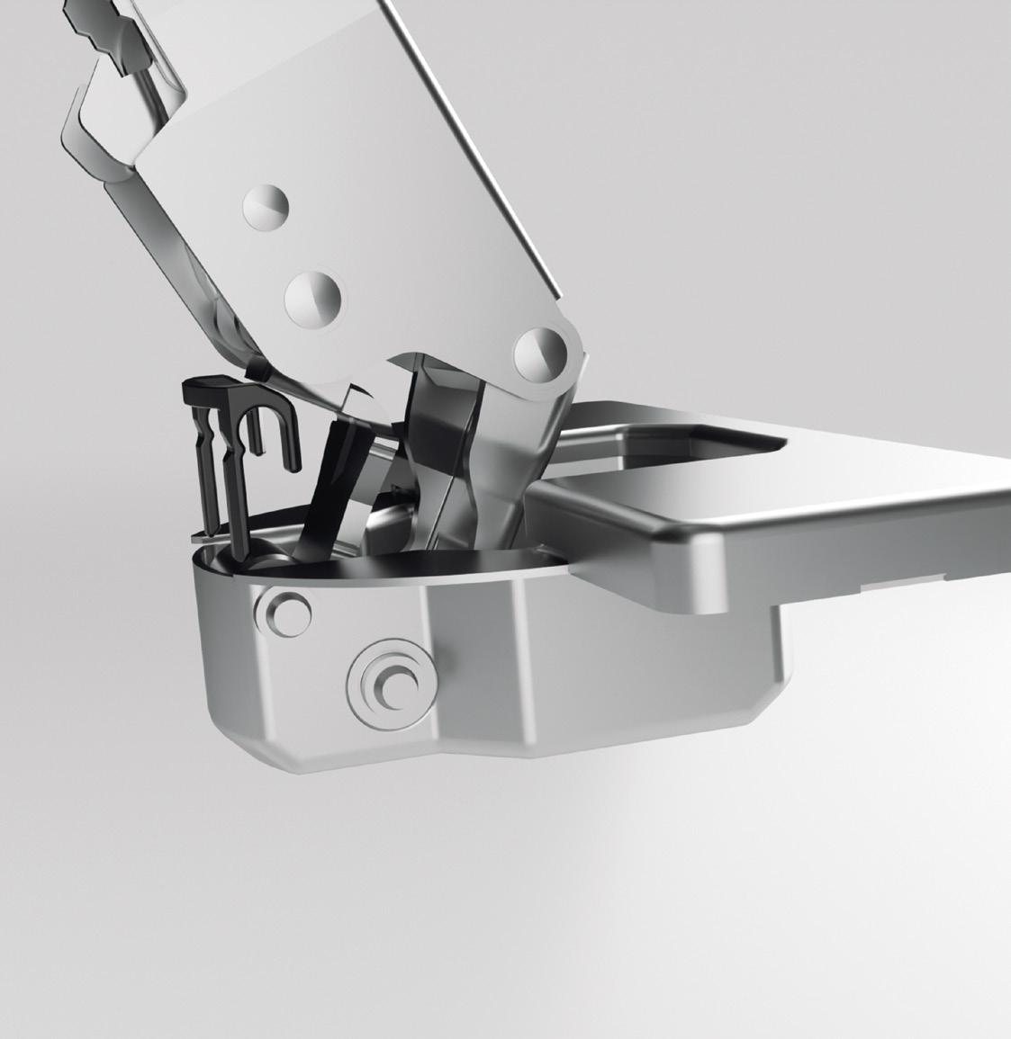
The Omnia L SlowMotion hinge is the new top product of the FGV’s offer originates from the research and the experience built up in over 70 years of presence in the field. Equipped with a state-of-the-art Linear SlowMotion Technology, it ensures stable and constant operation in all conditions of use. Produced in Italy it boosts all the best features and performances required by the market of damped systems.
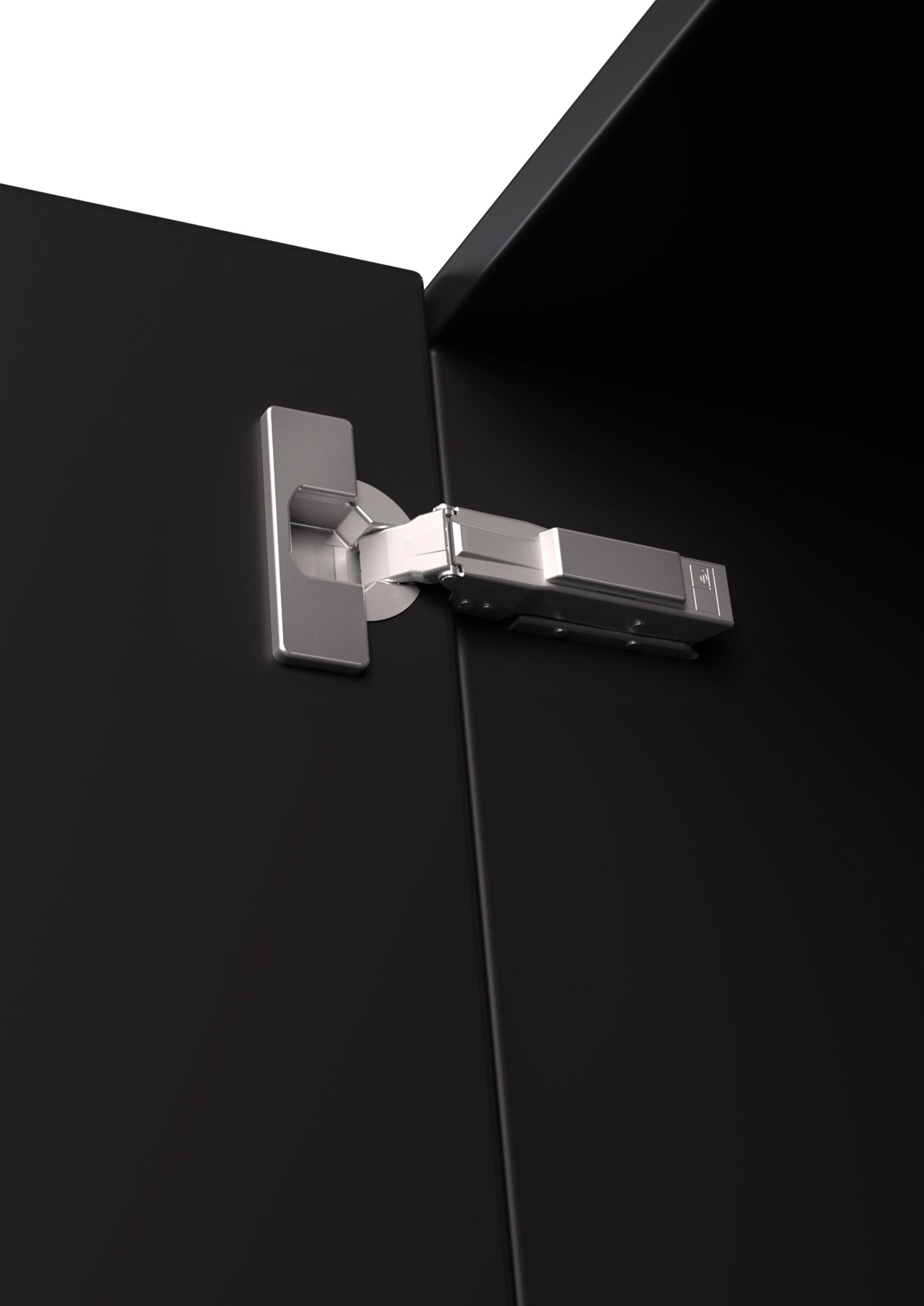
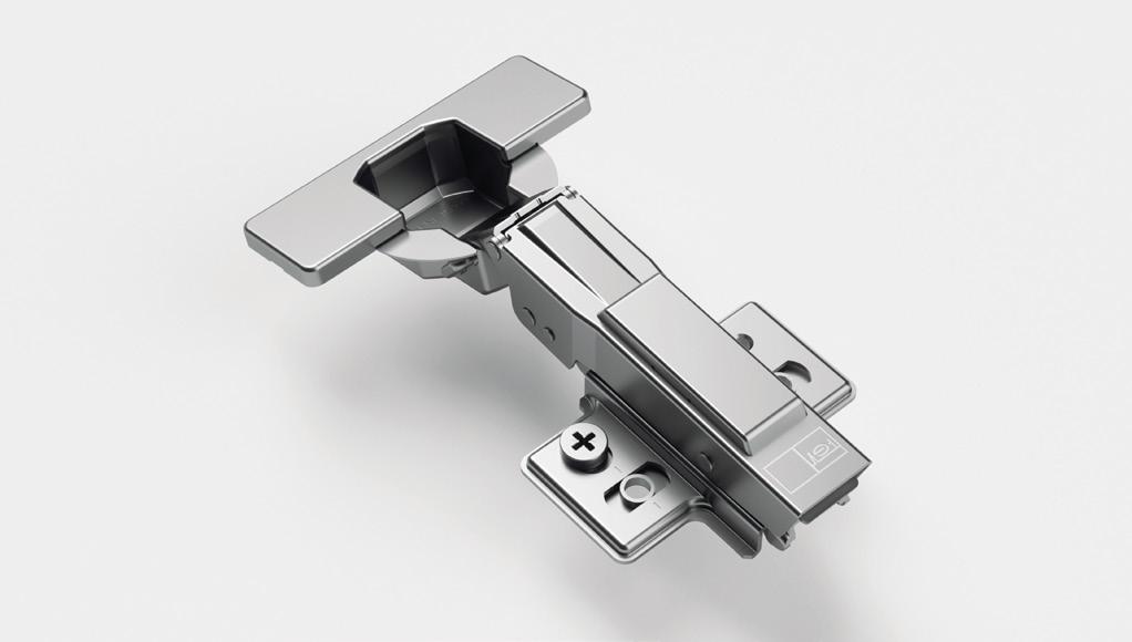
NEVER SO EASY TO HANG A DOOR!
No limits to door dimensions and to hinge numbers. AnyClickSystem an intelligent and practical solution to fit the hinges in any position without any stress. A really fantastic simplification for the wardrobe doors.
04
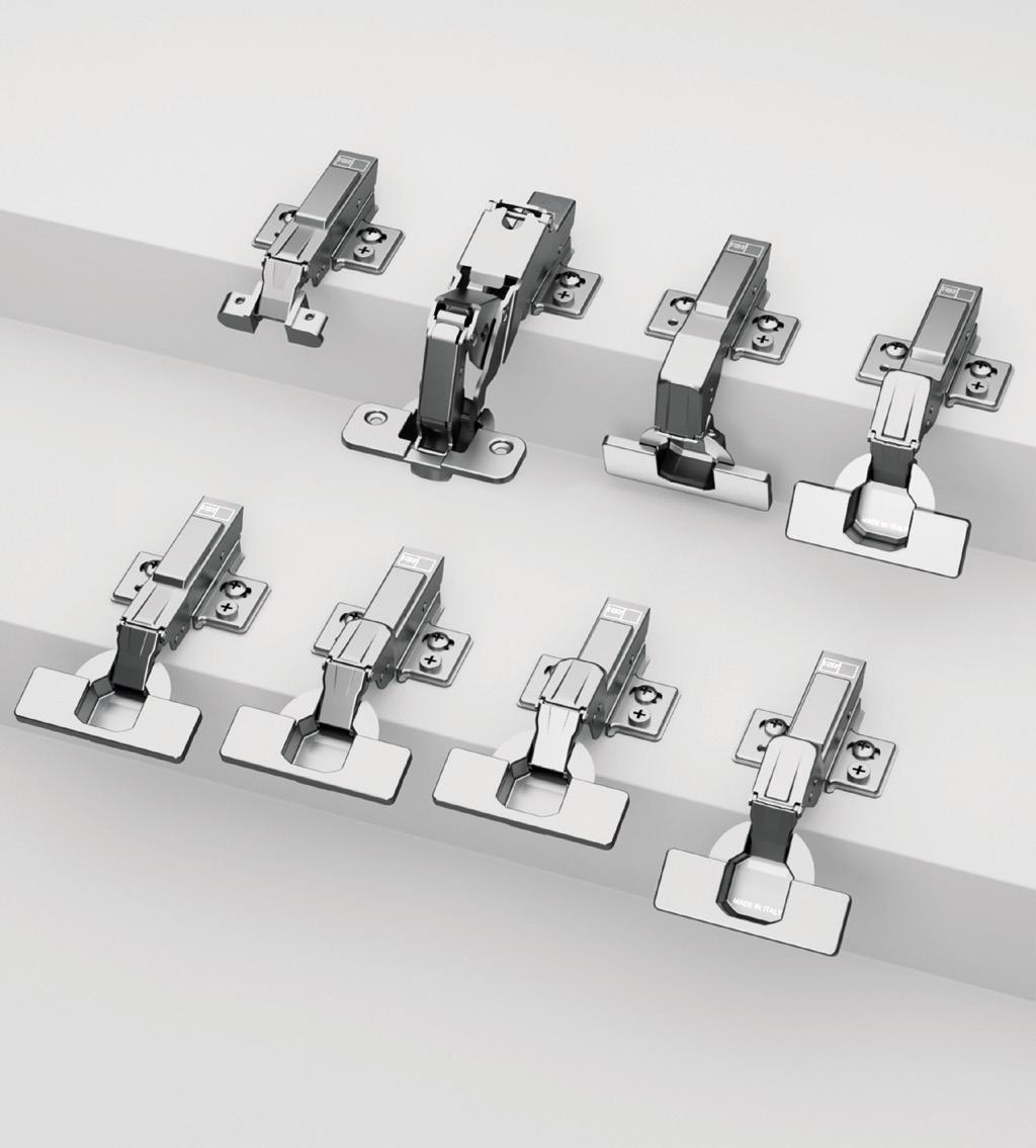
OMNIA L HINGE RANGE
A TECHNOLOGY TO COVER EVERY APPLICATION
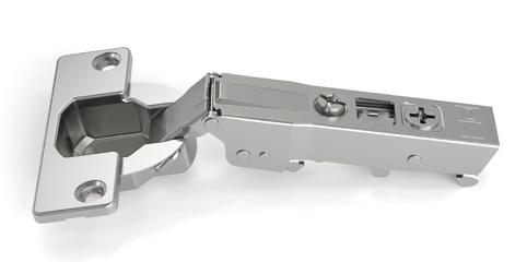
Full range of cranks and angle solutions; full choice of fixing systems, included the Velofix version. Range of reversible mounting plates with 3D independent adjustment: fast, simple, precise and intuitive.
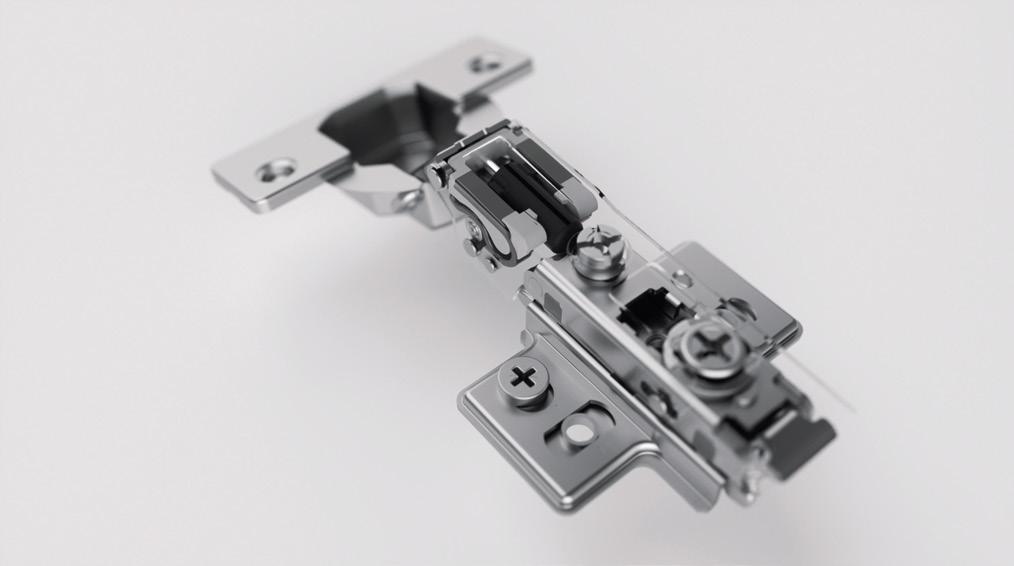
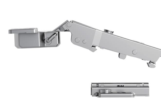
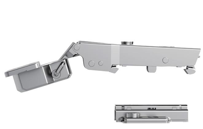
ALL THE BENEFITS FROM THE LINEAR SLOWMOTION
State-of-the-art Linear SlowMotion Technology, for a perfect damped closure in every condition, based on stable shock absorber at all high and low temperatures, adaptive controlled movement without manual adjustments, 25° of smooth braking to avoid door rebound.
05
06
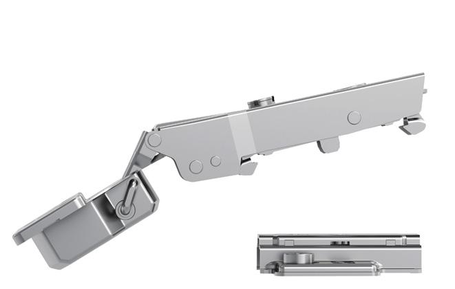
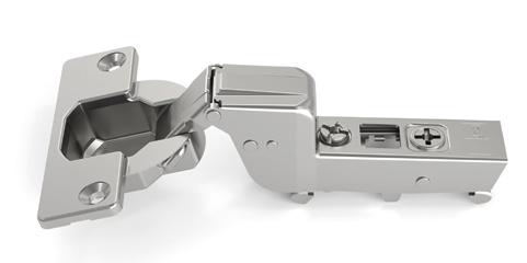
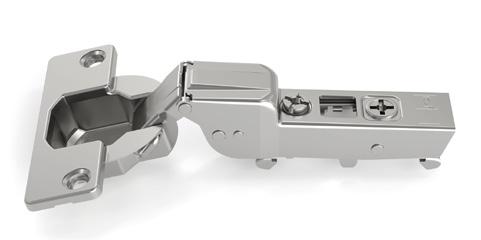
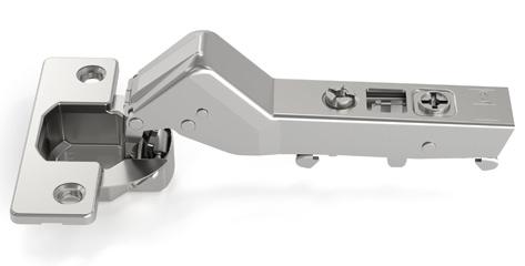
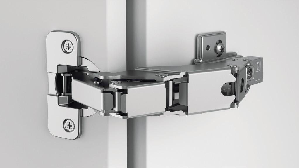
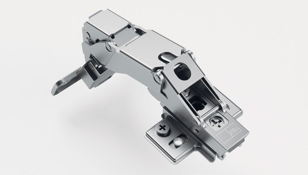
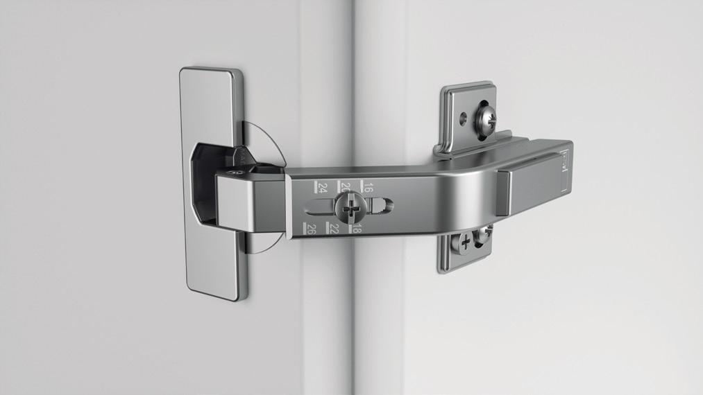
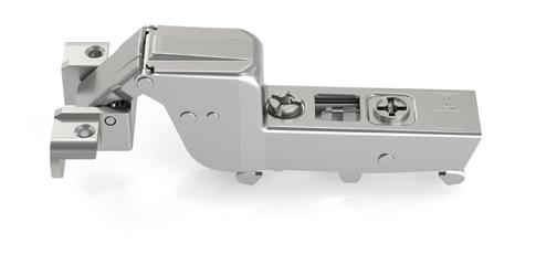
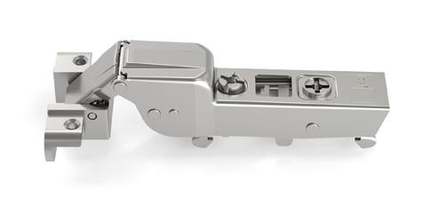
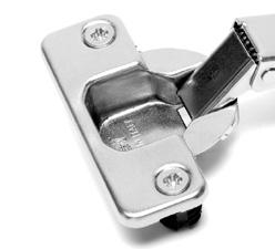
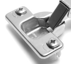
Omnia L
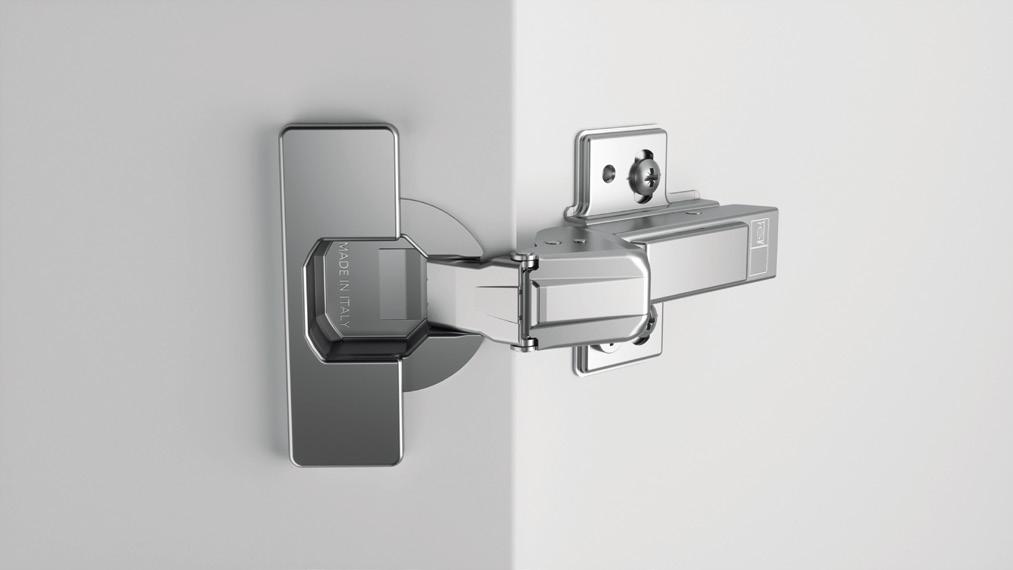
Modern and elegant design patented
Linear SlowMotion Damper hidden into the hinge arm
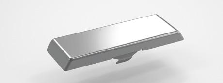
Box and Arm cover caps PERFORMANCE AnyClickSystem
Linear Linear SlowMotion Full range
Mounting Plate No rebound
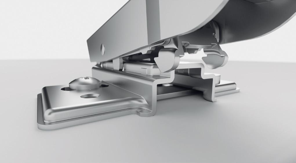
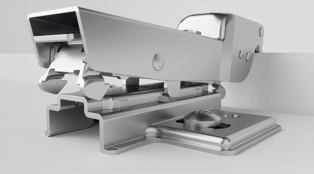
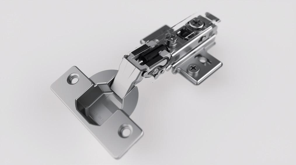
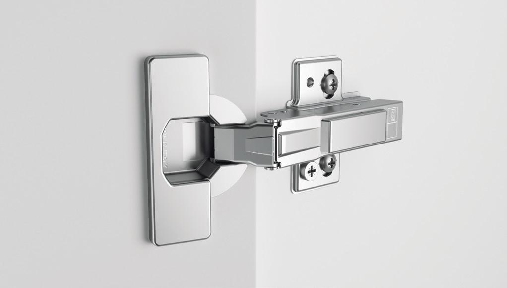
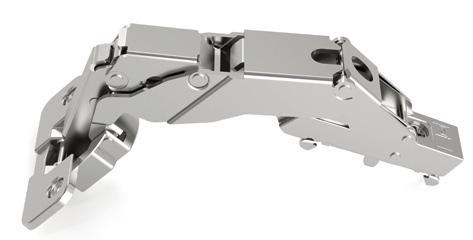
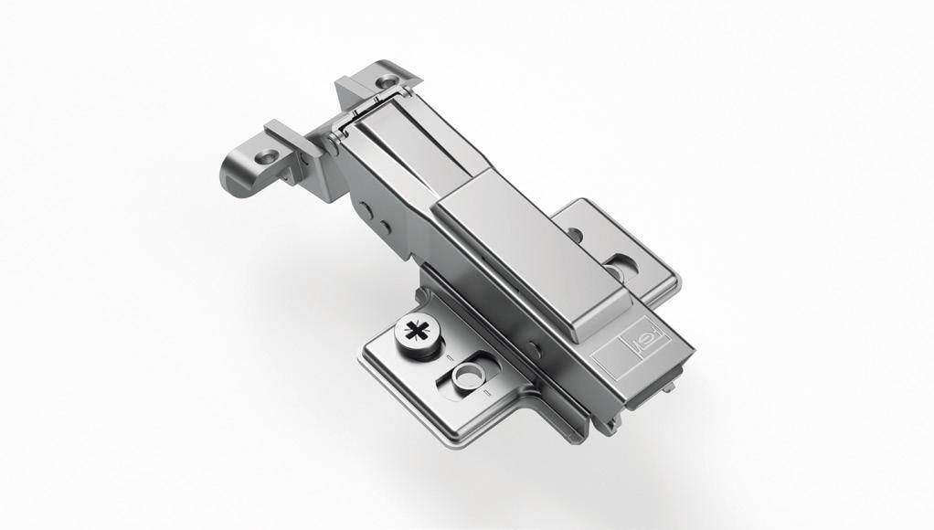
ANYCLICKSYSTEM
For an easy and quick fitting in any position.
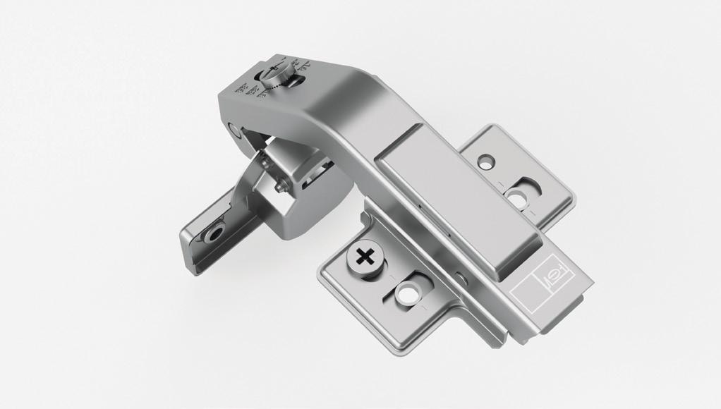
ADJUSTING SYSTEM
Depth adjustment
Acting on the “A” screw it is possible to adjust the distance between the side of the cabinet and the door.
Independent side adjustment
Acting on the “B” screw it is possible to change the amount of the door covering on the side of the cabinet.
A practical test is recommended to verify
Vertical adjustment
Acting on the “C” screw of the mounting plate it is possible to adjust the door vertically.
Values given in mm 07
L H 260 H = door height (cm)
the
hinges
L = door width (cm) 240 220 17 - 22 kg 4 - 5 damped 2 - 3 damped 1 - 2 damped 3 - 4 damped 12 - 17 kg 6 - 12 kg 0 - 6 kg 200 180 160 140 120 100 80 60 40 20 0 20 40 60 80 0
best
combination
Omnia L A B C +3/-2 mm +2/-3 mm +/-2 mm
Technical Specifications:
• Depth of the metal cup 11.4 mm
• Cup diameter 35 mm
• Opening 105°
• Possibility of door drilling (K) from 3 to 7 mm
• Thickness of the door (T) from 14 to 26 mm
• Available with cup hole distance I.48, A.45, D.52
• Complete program of fixing systems with Selftapping and Euro screw; Expanding, EasyFix and knock-in Dowel
51.LSW0.M9.08.IX000
51.LSW0.M9.08.AX000
51.LSW0.M9.08.DX000
51.LSW0.M9.15.IX000
51.LSW0.M9.15.AX000
51.LSW0.M9.15.DX000
Available also with premounted selftapping screw (sample code 51.LSWP.M9.00.IX000)
51.LSEP.M9.08.IX000
51.LSEP.M9.08.AX000
51.LSEP.M9.08.DX000
Available also without euro screw (sample code 51.LSE0.M9.00.IX000)
51.LSD0.M9.08.IX000
51.LSD8.M9.08.AX000
51.LSD0.M9.08.DX000
D0 = dowels Ø10 / D8 = dowels Ø8
51.LSV0.M9.08.IX000
51.LSV8.M9.08.AX000
51.LSV0.M9.08.DX000
V0 = dowels Ø10 / V8 = dowels Ø8
51.LSX0.M9.08.IX000
51.LSX8.M9.08.AX000
51.LSX0.M9.08.DX000
X0 = dowels Ø10 / X8 = dowels Ø8
Versions not damped available for all applications in the above table (sample code 51.LSW0.M9.00.I0000)
51.LSEP.M9.15.IX000
51.LSEP.M9.15.AX000
51.LSV0.M9.15.IX000
51.LSV8.M9.15.AX000
51.LSV0.M9.15.DX000
51.LSX0.M9.15.IX000
51.LSX8.M9.15.AX000
51.LSX0.M9.15.DX000
Values given in mm
08
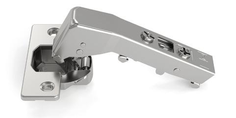
Omnia L 105°
For mounting plates and fittings see pages 18 - 25.
CRANK
0
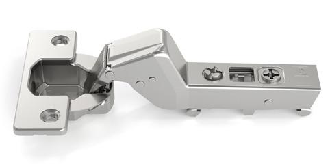
CRANK 8
51.LSW0.M9.00.IX000 51.LSW0.M9.00.AX000 51.LSW0.M9.00.DX000 51.LSEP.M9.00.IX000 51.LSEP.M9.00.AX000 51.LSEP.M9.00.DX000 51.LSD0.M9.00.IX000 51.LSD8.M9.00.AX000 51.LSD0.M9.00.DX000 51.LSX0.M9.00.IX000 51.LSX8.M9.00.AX000 51.LSX0.M9.00.DX000 51.LSV0.M9.00.IX000 51.LSV8.M9.00.AX000 51.LSV0.M9.00.DX000
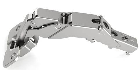
CRANK 15
51.LSEP.M9.15.DX000 51.LSD0.M9.15.IX000 51.LSD8.M9.15.AX000 51.LSD0.M9.15.DX000
CRANK 0 For lay-on doors
CRANK
with
between two values get the lower one
CRANK 15 For inset doors
= with H between two values get the lower one
Table to determinate the minimum distance A so that a door with T thickness can open without protrusion from the cabinet and without interfering with adjacent doors.
8 For partial lay-on doors
09 Omnia L 105°
*
* = with H
3 4 5 6 7 19 0 18 0 2 17 0 2 16 0 2 4 15 2 4 14 2 4 6 13 4 6 12 4 6 11 6 10 6 14 15 16 17 18 19 20 21 22 23 24 25 26 0.1 0.2 0.3 0.4 0.5 0.7 0.8 1 1.2 2 3.2 4.5 5.8 0.1 0.2 0.3 0.4 0.5 0.6 0.8 1 1.2 1.4 2.2 3.5 4.9 0.1 0.2 0.3 0.3 0.5 0.6 0.8 1 1.2 1.4 1.6 2.5 3.8 0.1 0.2 0.3 0.3 0.5 0.6 0.8 1 1.2 1.4 1.6 1.9 2.8 0.1 0.2 0.3 0.3 0.5 0.6 0.8 1 1.2 1.4 1.6 1.9 2.8 3 4 5 6 7 11 0 10 0 2 9 0 2 8 0 2 4 7 2 4 6 2 4 6 5 4 6 4 4 6 3 6 2 6 3 4 5 6 7 1 0 2 4 0 2 4 -1 2 4 6 -2 4 6 -3 4 6 -4 6 -5 -6 -7 -8 H* H* H* Drilling distance (k) T= A= A= A= A= A= K=3 K=4 K=5 K=6 K=7 Drilling distance (k) Drilling distance (k) Overlay (C) Crank 0 Overlay (C) Crank 8 Overlay (C) Crank 15 19.7 (H0) 8.3 105° S T C A 67 10.5 (K3) T 67 C A S 27.7 (H0) 16.3 105° 18.5 (K3) L S T 67 A 37+L+ T 36.7 (H2) 25.3 27.5 (K3) 105°
*
=
H
between two values get the lower one
Values given in mm
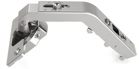
Omnia L 105° for corner doors
Technical Specifications:
• Depth of the metal cup 11.4 mm
• Cup diameter 35 mm
• Opening 105°
• Possibility of door drilling (K) from 3 to 7 mm
• Thickness of the door (T) from 14 to 26 mm
• Available with cup hole distance I.48, A.45, D.52
• Complete program of fixing systems with Selftapping and Euro screw; Expanding, EasyFix and knock-in Dowel
51.LSW0.M9.90.IX000
51.LSW0.M9.90.AX000
51.LSW0.M9.90.DX000
Available also with premounted selftapping screw (sample code 51.LSWP.M9.30.IX000)
51.LSEP.M9.90.IX000
51.LSEP.M9.90.AX000 51.LSEP.M9.90.DX000
Available also without euro screw (sample code 51.LSE0.M9.30.IX000)
51.LSD0.M9.45.IX000
51.LSD8.M9.45.AX000
51.LSD0.M9.45.DX000
D0 = dowels Ø10 / D8 = dowels Ø8
51.LSV0.M9.45.IX000
51.LSV8.M9.45.AX000
51.LSV0.M9.45.DX000
V0 = dowels Ø10 / V8 = dowels Ø8
51.LSX0.M9.45.IX000
51.LSX8.M9.45.AX000
51.LSX0.M9.45.DX000
X0 = dowels Ø10 / X8 = dowels Ø8
Versions not damped available for all applications in the above table (sample code 51.LSW0.M9.30.I0000)
51.LSD0.M9.90.IX000 51.LSD8.M9.90.AX000 51.LSD0.M9.90.DX000
51.LSV0.M9.90.IX000
51.LSV8.M9.90.AX000
51.LSV0.M9.90.DX000
51.LSX0.M9.90.IX000
51.LSX8.M9.90.AX000
51.LSX0.M9.90.DX000
Values given in mm
10
For mounting plates and fittings see pages 18 - 25.
51.LSW0.M9.30.IX000 51.LSW0.M9.30.AX000 51.LSW0.M9.30.DX000 51.LSEP.M9.30.IX000 51.LSEP.M9.30.AX000 51.LSEP.M9.30.DX000 51.LSD0.M9.30.IX000 51.LSD8.M9.30.AX000 51.LSD0.M9.30.DX000 51.LSX0.M9.30.IX000 51.LSX8.M9.30.AX000 51.LSX0.M9.30.DX000 51.LSV0.M9.30.IX000 51.LSV8.M9.30.AX000 51.LSV0.M9.30.DX000
ANGLE 24° / 30° ANGLE 45° ANGLE 90°
51.LSW0.M9.45.IX000 51.LSW0.M9.45.AX000 51.LSW0.M9.45.DX000
51.LSEP.M9.45.IX000 51.LSEP.M9.45.AX000 51.LSEP.M9.45.DX000
Omnia L 105° for corner doors
ANGLE 24° / 30°
ANGLE 45°
Table to determinate the minimum distance
A so that a door with T thickness can open without protrusion from the cabinet and without interfering with adjacent doors.
13
ANGLE 90°
14 15 16 17 18 19 20 21 22 23 24 25 26 0.1 0.2 0.3 0.4 0.5 0.7 0.8 1 1.2 2 3.2 4.5 5.8 0.1 0.2 0.3 0.4 0.5 0.6 0.8 1 1.2 1.4 2.2 3.5 4.9 0.1 0.2 0.3 0.3 0.5 0.6 0.8 1 1.2 1.4 1.6 2.5 3.8 0.1 0.2 0.3 0.3 0.5 0.6 0.8 1 1.2 1.4 1.6 1.9 2.8 0.1 0.2 0.3 0.3 0.5 0.6 0.8 1 1.2 1.4 1.6 1.9 2.8 T= A= A= A= A= A= K=3 K=4 K=5 K=6 K=7 S T K=5 2430° ° 65 40 (H4) S T K=5 45° 65 38 (H4) 21 S 22.5 (H4) T K= 5 49 90° Values given in mm
Technical Specifications:
• Depth of the metal cup 11.3 mm
• Cup diameter 35 mm
• Opening 155°
• Possibility of door drilling (K) from 3 to 7 mm
• Thickness of the door (T) from 14 to 26 mm
• Available with cup hole distance I.48, A.45, D.52
• Complete program of fixing systems with Selftapping and Euro screw; EasyFix and knock-in Dowel
51.LWEP.M9.08.IX000
51.LWEP.M9.08.AX000
51.LWEP.M9.08.DX000
Available also without euro screw (sample code 51.LWE0.M9.00.IX000)
51.LWD0.M9.08.IX000
51.LWD8.M9.08.AX000
51.LWD0.M9.08.DX000
51.LWV0.M9.08.IX000
51.LWV0.M9.08.DX000
L 155° 12
Omnia
For mounting plates and fittings see pages 18 - 25.
CRANK 0
51.LWW0.M9.00.IX000 51.LWW0.M9.00.AX000 51.LWW0.M9.00.DX000 51.LWEP.M9.00.IX000 51.LWEP.M9.00.AX000 51.LWEP.M9.00.DX000
51.LWD8.M9.00.AX000 51.LWD0.M9.00.DX000
CRANK 8
51.LWD0.M9.00.IX000
51.LWV0.M9.00.IX000 51.LWV0.M9.00.DX000 51.LWW0.M9.08.IX000 51.LWW0.M9.08.AX000 51.LWW0.M9.08.DX000
D0 = dowels Ø10 / D8 = dowels Ø8
Values given in mm
V0 = dowels Ø10
Versions not damped available for all applications in the above table (sample code 51.LWW0.M9.00.I0000)
CRANK 0 For lay-on doors
CRANK 8 For partial lay-on doors
Table to determinate the minimum distance A so that a door with T thickness can open without protrusion from the cabinet and without interfering with adjacent doors.
15
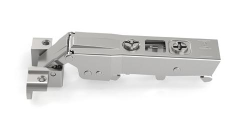
Omnia L 155°
3 4 5 6 7 19 0 18 0 2 17 0 2 16 0 2 4 15 2 4 14 2 4 6 13 4 6 12 4 6 11 6 10 6 14 15 16 17 18 19 20 21 22 23 24 25 26 0 0 0 0 0 0 0 0 0 0 0 13.7 18 0 0 0 0 0 0 0 0 0 0 0 12.7 17 0 0 0 0 0 0 0 0 0 0 7.4 11.7 16 0 0 0 0 0 0 0 0 0 0 6.4 10.7 15 0 0 0 0 0 0 0 0 0 0 5.4 9.7 14 3 4 5 6 7 11 0 10 0 2 9 0 2 8 0 2 4 7 2 4 6 2 4 6 5 4 6 4 4 6 3 6 2 6 Drilling distance (k) T= A= A= A= A= A= K=3 K=4 K=5 K=6 K=7 Drilling distance (k) Overlay (C) Crank 0 Overlay (C) Crank 8 1.6 45 (H0) S S T 71 C A 57.5 (H0) K 28 (H0) 23max. 23 max. S T 71 C 66 (H0) A S 54 (H0) 7.4 23max. 23 max. 37 (H0) K S * = with H between two values get the lower one * = with H between two values get the lower one H* H* Values given in mm
Omnia L for corner cabinet 90°
For mounting plates and fittings see pages 18 - 25.
Technical Specifications:
• Depth of the metal cup 11.4 mm
• Cup diameter 35 mm
• Opening 50°
• Possibility of door drilling (K) from 3 to 7 mm
• Thickness of the door (T) from 14 to 26 mm
• Available with cup hole distance I.48, A.45, D.52
• Complete program of fixing systems with Selftapping and Euro screw; Expanding, EasyFix and knock-in Dowel
51.LPW0.M9.00.I0000
51.LPW0.M9.00.A0000
51.LPW0.M9.00.D0000
Available also with premounted selftapping screw (sample code 51.LPWP.M9.00.I0000)
51.LPEP.M9.00.I0000
51.LPEP.M9.00.A0000
51.LPEP.M9.00.D0000
Available also without euro screw (sample code 51.LPE0.M9.00.I0000)
51.LPD0.M9.00.I0000
51.LPD8.M9.00.A0000
51.LPD0.M9.00.D0000
D0 = dowels Ø10 / D8 = dowels Ø8
51.LPV0.M9.00.I0000
51.LPV8.M9.00.A0000
51.LPV0.M9.00.D0000
V0 = dowels Ø10 / V8 = dowels Ø8
51.LPX0.M9.00.I0000
51.LPX8.M9.00.A0000
51.LPX0.M9.00.D0000
X0 = dowels Ø10 / X8 = dowels Ø8
For all applications in the above table available only versions not damped
14
Values given in mm
15 Omnia L for corner cabinet 90° K=5 37 H0 50° Values given in mm
Omnia L 105° for doors with aluminium frame
Technical Specifications:
• Depth of the zamak cup 9.9 mm
• Cup drilling 28x7 mm
• Opening 105°
• Aluminium frame from min. 19 to max 26 mm
• Available with cup hole distance I.48, A.45, D.52
• Complete program of fixing systems with Selftapping and Euro screw; Expanding, EasyFix and knock-in Dowel
Versions not damped available for all applications in the above table (sample code
Drilling holes
The two laterals drillings are Ø4 mm and are countersunk with 120°. Screws Ø3.5x12 mm supplied on demand under code 1A05512105000.
For mounting plates and fittings see pages 18 - 25.
16
instructions CRANK 0 CRANK 15 CRANK 8 51.LSA0.M9.00.0X000 51.LSA0.M9.08.0X000 51.LSA0.M9.15.0X000 1 2 16.5 Ø 4 10 7 28 19 32 +0.1 0 +0.1 0 Values given in mm
Assembly
51.LSA0.M9.00.00000)
Omnia L 105° for doors with aluminium frame
CRANK 0 For lay-on doors
CRANK 8 For partial lay-on doors
CRANK 15 For inset doors
Table to determinate the minimum distance A so that a door with T thickness can open without protrusion from the cabinet and without interfering with adjacent doors.
Values given in mm
19
19 16 0 15 14 2 13 12 4 11 10 6 19 8 0 7 6 2 5 4 4 3 2 6 19 1 0 0 -1 2 -2 -3 4 -4 -5 6 19 20 21 22 23 24 25 26 0.7 0.8 1 1.2 2 3.2 4.5 5.8 0.6 0.8 1 1.2 1.4 2.2 3.5 4.9 0.6 0.8 1 1.2 1.4 1.6 2.5 3.8 0.6 0.8 1 1.2 1.4 1.6 1.9 2.8 0.6 0.8 1 1.2 1.4 1.6 1.9 2.8 Profile height (P) Profile height (P) Profile height (P) T= A= A= A= A= A= P=19 P=20 P=21 P=22 P=23 Overlay (C) Crank 0 Overlay (C) Crank 8 Overlay (C) Crank 15 S 67 C A T P 19.7 (H0) 8.3 105° 10.5 (P19) S T C A P 28.4 (H0) 16.3 105° 18.5 (P19) S A 37 L T P 37+L+ T 36.7 (H2) 105° 27.5 (P19) H* H* H* * = with H between two values get the lower one
= with H between two values get the lower one * = with H between two values get the lower one
*
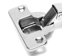
Mounting Plates Series Omnia L
Linear mounting plates
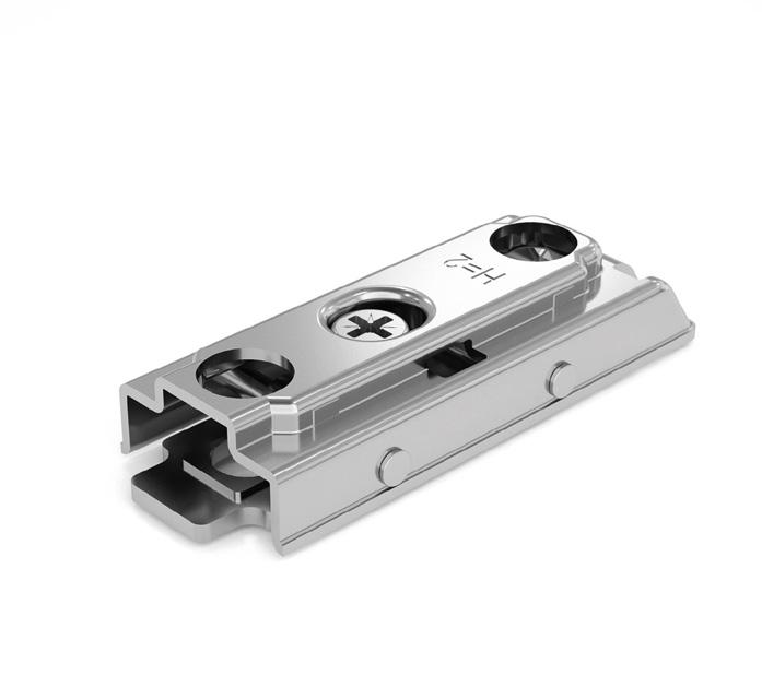
Metal linear mounting plate. Fixing by Selftapping screw. Independent vertical adjustment with CAM.
(For screws see page 25)
Height Material Code
H0 Metal 52.LLW0.M9.00.00000
H2 Metal 52.LLW0.M9.02.00000
H4 Metal 52.LLW0.M9.04.00000
Metal linear mounting plate. Fixing by premounted Euro screws. Independent vertical adjustment with CAM.
Height Material Code
H0 Metal 52.LL**.M9.00.00000
H2 Metal 52.LL**.M9.02.00000
H4 Metal 52.LL**.M9.04.00000
Metal linear mounting plate. Fixing by Expanding dowels Ø5mm. Independent vertical adjustment with CAM.
Height Material Code
H0 Metal 52.LL**.M9.00.00000
H2 Metal 52.LL**.M9.02.00000
H4 Metal 52.LL**.M9.04.00000
Metal linear mounting plate. Fixing by Knock-in dowels Ø10mm. Independent vertical adjustment with CAM.
Height Material Code
H0 Metal 52.LL**.M9.00.00000
H2 Metal 52.LL**.M9.02.00000
H4 Metal 52.LL**.M9.04.00000
18
Attention: the picture shows the real product, the drawing shows drilling and mounting instruction. 32 64.5 19.6 H H H H L L L 32 21 21 Ø Ø=2 Ø=5 Ø=5 Ø Ø=5 Ø Ø=5 Ø=2 21 21 21 21 Values given in mm ** euro screw: ED = L12 / EC = L15 ** dowel: X4 = L7.5 / X5 = L9 ** dowel: D8 = Ø8xL10 / D0 = Ø10xL10
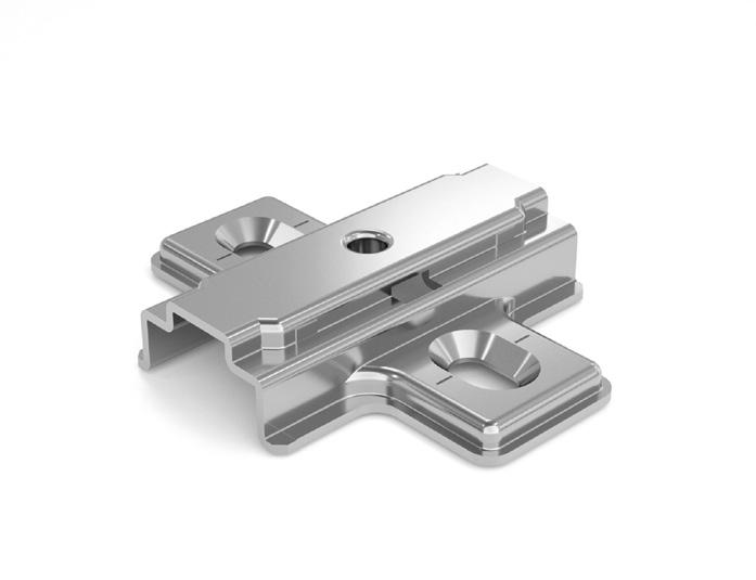
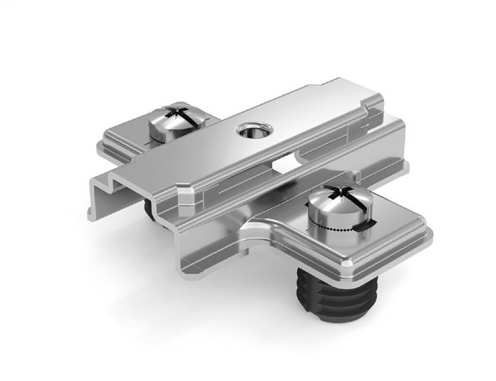
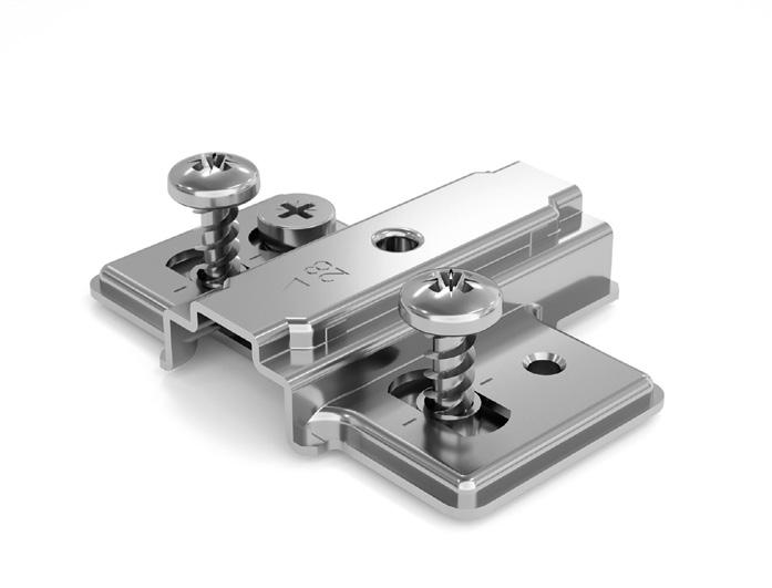
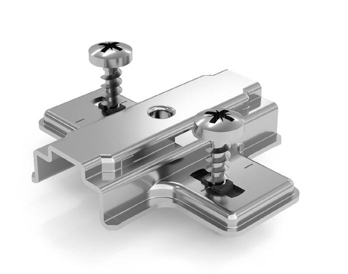
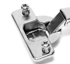
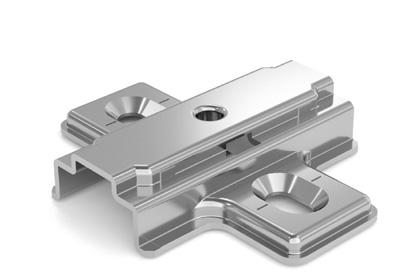
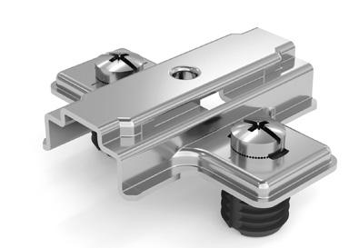
Cruciform mounting plates
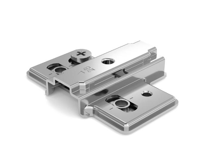
Metal cruciform mounting plate. Fixing by Selftapping screw. Vertical adjustment. (For screws see page 25)
Height Material Code
H0 Metal 52.LCW0.M9.00.00000
H2 Metal 52.LCW0.M9.02.00000
H4 Metal 52.LCW0.M9.04.00000
H6 Metal 52.LCW0.M9.06.00000
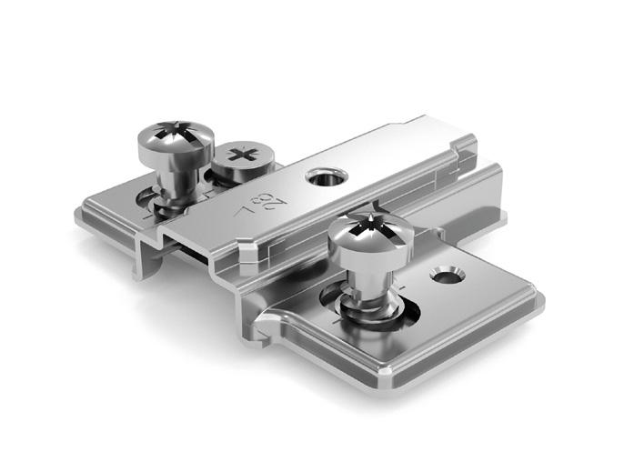
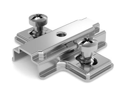
Metal cruciform mounting plate. Fixing by premounted Selftapping screws Ø4.7mm. Vertical adjustment.
Height Material Code
H0 Metal 52.LCWP.M9.00.00000
H2 Metal 52.LCWP.M9.02.00000
H4 Metal 52.LCWP.M9.04.00000
H6 Metal 52.LCWP.M9.06.00000
Metal cruciform mounting plate. Fixing by premounted Euro screws. Vertical adjustment.
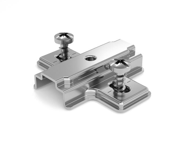
Height Material Code
H0 Metal 52.LC**.M9.00.00000
H2 Metal 52.LC**.M9.02.00000
H4 Metal 52.LC**.M9.04.00000
H6 Metal 52.LC**.M9.06.00000
Metal cruciform mounting plate. Fixing by Expanding dowels Ø5mm. Vertical adjustment.
Height Material Code
H0 Metal 52.LC**.M9.00.00000
H2 Metal 52.LC**.M9.02.00000
H4 Metal 52.LC**.M9.04.00000
H6 Metal 52.LC**.M9.06.00000
Metal cruciform mounting plate. Fixing by Knock-in dowels Ø10mm. Vertical adjustment.
Height Material Code
H0 Metal 52.LC**.M9.00.00000
H2 Metal 52.LC**.M9.02.00000
H4 Metal 52.LC**.M9.04.00000
H6 Metal 52.LC**.M9.06.00000
19
37 37 37 37 37 32 37 Ø 51 H H H H H 15 L L L 32 37 Ø=2 Ø=3 Ø=5 Ø=5 Ø Values given in mm ** euro screw: EH = L10 / ED = L12 / EC = L14 ** dowel: X4 = L7.5 / X5 = L9 ** dowel: D8 = Ø8xL10 / D0 = Ø10xL10
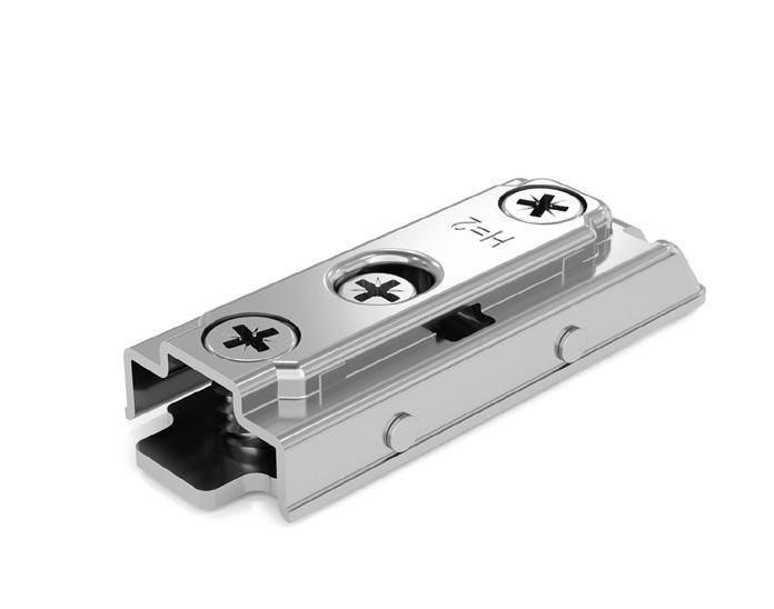
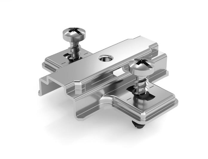
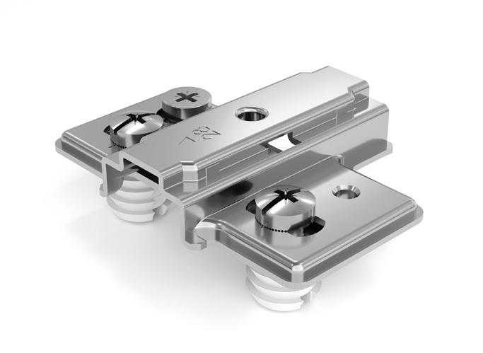
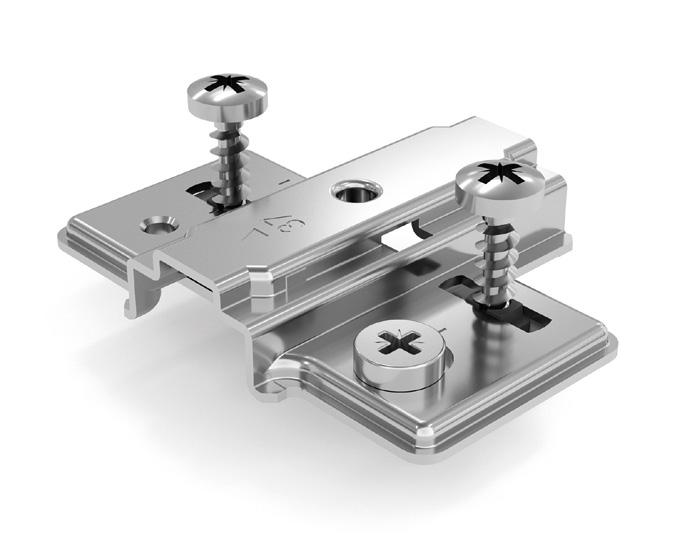
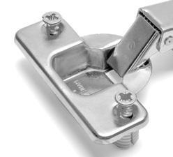
Metal cruciform mounting plate. Fixing by Selftapping screw. Independent vertical adjustment with CAM. (For screws see page 25)
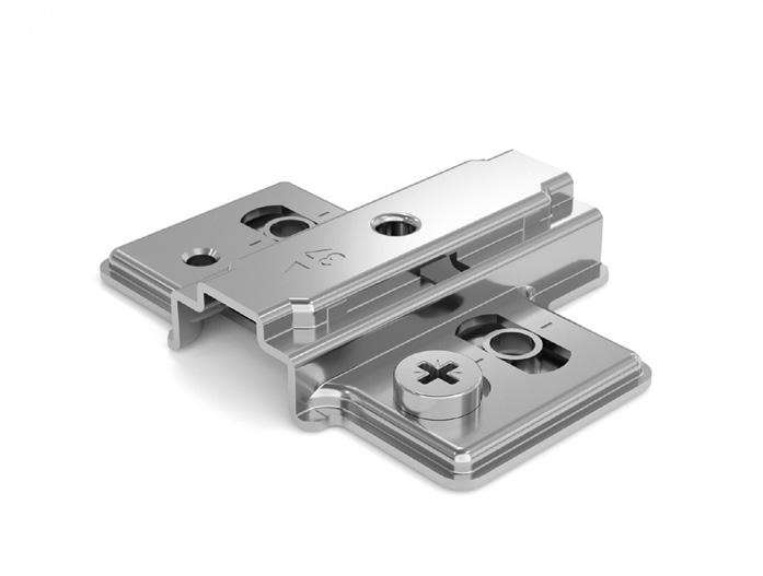
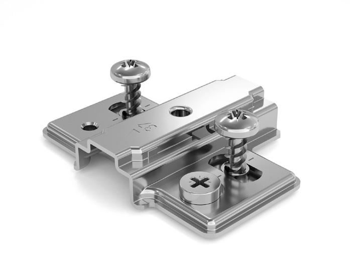
Height Material Code
H0 Metal 52.LDW0.M9.00.00000
H2 Metal 52.LDW0.M9.02.00000
H4 Metal 52.LDW0.M9.04.00000
H6 Metal 52.LDW0.M9.06.00000
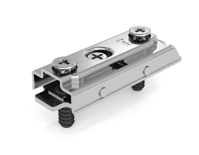
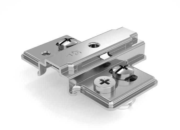
Metal cruciform mounting plate. Fixing by premouned Selftapping screw. Independent vertical adjustment with CAM.
Height Material Code
H0 Metal 52.LDWP.M9.00.00000
H2 Metal 52.LDWP.M9.02.00000
H4 Metal 52.LDWP.M9.04.00000
H6 Metal 52.LDWP.M9.06.00000
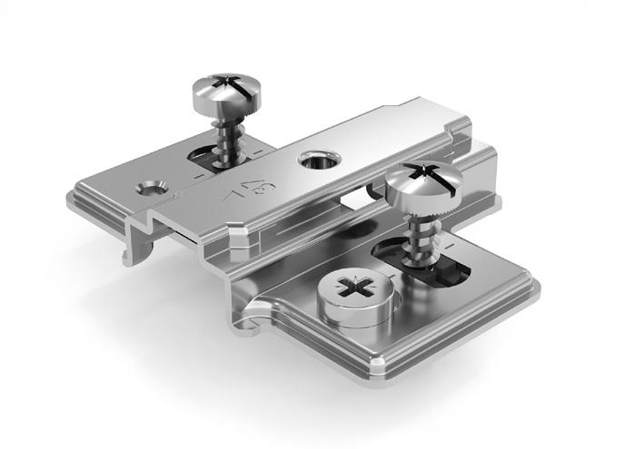
Metal cruciform mounting plate. Fixing by premouned Euro screws. Independent vertical adjustment with CAM.
Height Material Code
H0 Metal 52.LD**.M9.00.00000
H2 Metal 52.LD**.M9.02.00000
H4 Metal 52.LD**.M9.04.00000
H6 Metal 52.LD**.M9.06.00000
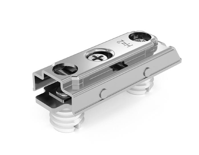
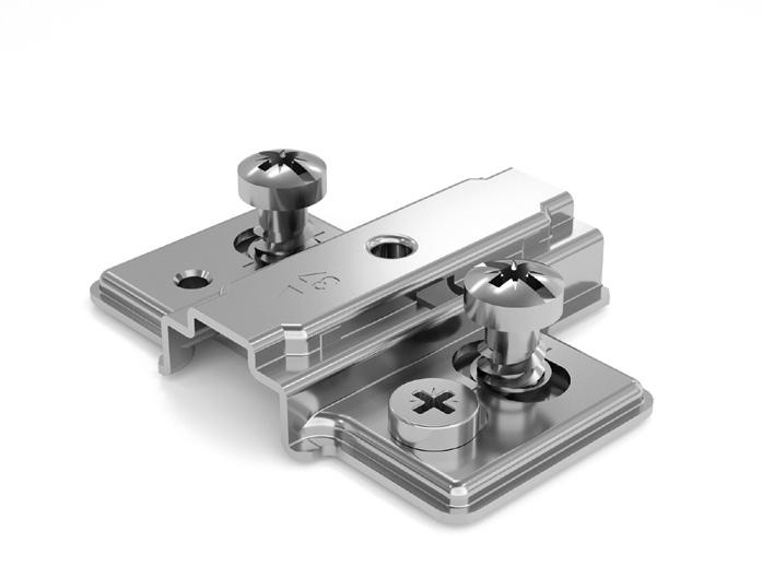
Metal cruciform mounting plate. Fixing by Expanding dowels Ø5mm. Independent vertical adjustment with CAM.
Height Material Code
H0 Metal 52.LD**.M9.00.00000
H2 Metal 52.LD**.M9.02.00000
H4 Metal 52.LD**.M9.04.00000
H6 Metal 52.LD**.M9.06.00000
Metal cruciform mounting plate. Fixing by Knock-in dowels Ø10mm. Independent vertical adjustment with CAM.
Height Material Code
H0 Metal 52.LD**.M9.00.00000
H2 Metal 52.LD**.M9.02.00000
H4 Metal 52.LD**.M9.04.00000
H6 Metal 52.LD**.M9.06.00000
20 Cruciform mounting plates with CAM 32 54 32 37 37 Ø 37 37 37 37 37 H H H H H L L 14.5 L Ø=2 Ø=3 Ø=5 Ø=5 Ø Values given in mm ** euro screw: EH = L10 / ED = L12 / EC = L14 ** dowel: X4 = L7.5 / X5 = L9 ** dowel: D8 = Ø8xL10 / D0 = Ø10xL10
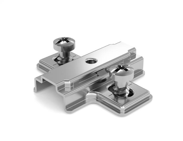
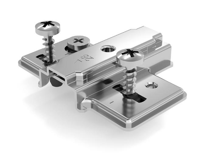
Metal cruciform mounting plate. Fixing by Selftapping screw. Independent vertical adjustment with CAM. (For screws see page 25)
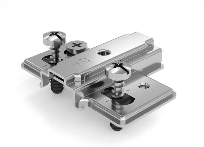
Height Material Code
H0 Metal 52.LBW0.M9.00.00000
H2 Metal 52.LBW0.M9.02.00000
H4 Metal 52.LBW0.M9.04.00000
H6 Metal 52.LBW0.M9.06.00000
Metal cruciform mounting plate. Fixing by premouned Selftapping screw. Independent vertical adjustment with CAM.
Height Material Code
H0 Metal 52.LBWP.M9.00.00000
H2 Metal 52.LBWP.M9.02.00000
H4 Metal 52.LBWP.M9.04.00000
H6 Metal 52.LBWP.M9.06.00000
Metal cruciform mounting plate. Fixing by premouned Euro screws. Independent vertical adjustment with CAM.
Height Material Code
H0 Metal 52.LB**.M9.00.00000
H2 Metal 52.LB**.M9.02.00000
H4 Metal 52.LB**.M9.04.00000
H6 Metal 52.LB**.M9.06.00000
Metal cruciform mounting plate. Fixing by Expanding dowels Ø5mm. Independent vertical adjustment with CAM.
Height Material Code
H0 Metal 52.LB**.M9.00.00000
H2 Metal 52.LB**.M9.02.00000
H4 Metal 52.LB**.M9.04.00000
H6 Metal 52.LB**.M9.06.00000
Metal cruciform mounting plate. Fixing by Knock-in dowels Ø10mm. Independent vertical adjustment with CAM.
Height Material Code
H0 Metal 52.LB**.M9.00.00000
H2 Metal 52.LB**.M9.02.00000
H4 Metal 52.LB**.M9.04.00000
H6 Metal 52.LB**.M9.06.00000
21 Cruciform mounting plates with CAM 28 28 28 28 28 H H H H 14.5 L L L Ø=3 Ø=5 Ø=5 Ø 32 28 Ø 54 32 28 H Ø=2 Values given in mm ** euro screw: EH = L10 / ED = L12 / EC = L14 ** dowel: X4 = L7.5 / X5 = L9 ** dowel: D8 = Ø8xL10 / D0 = Ø10xL10
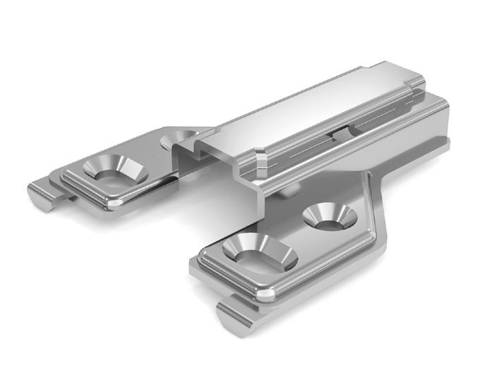
Metal face frame mounting plate. Fixing by Selftapping screw. Vertical adjustment. (For screws see page 25)
Height Material Code
H0 Metal 52.LFW0.M9.00.00000
H3 Metal 52.LFW0.M9.03.00000
Metal face frame mounting plate. Fixing by Selftapping screw. Vertical adjustment. (For screws see page 25)
Height Material Code
H0 Metal 52.LHW0.M9.00.00000
H3 Metal 52.LHW0.M9.03.00000
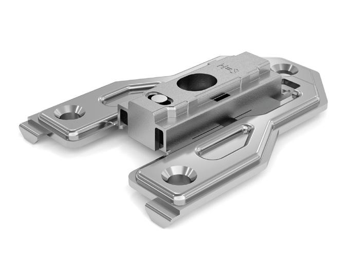
Metal face frame mounting plate. Fixing by Selftapping screw. Independent vertical adjustment with CAM.
(For screws see page 25)
Height Material Code
H0 Metal 52.LGW0.M9.00.00000
H3 Metal 52.LGW0.M9.03.00000
Metal face frame mounting plate. Fixing by Selftapping screw. Independent vertical adjustment with CAM.
(For screws see page 25)
Height Material Code
H0 Metal 52.LIW0.M9.00.00000
H3 Metal 52.LIW0.M9.03.00000
22 Face frame mounting plates 32 32 == == Ø Ø 50 56 56 50 32 40 40 32 H H H H Ø=2 Ø=2 Ø=2 Ø=2 9.5 9.5 12.5 12.5 58 77 77 58 12.5 12.5 9.5 9.5 Values given in mm
Metal asymmetric mounting plate for central panel. Fixing by Expanding dowels Ø5mm. Vertical adjustment.
Metal asymmetric mounting plate for central panel. Fixing by Expanding dowels Ø5mm. Independent vertical adjustment with CAM.
52.LQD5.M9.00.00000
H2 Metal 52.LQD5.M9.02.00000 H4
52.LQD5.M9.04.00000 H6 Metal 52.LQD5.M9.06.00000 Height Material Code H0 Metal 52.LPD5.M9.00.00000 H2 Metal 52.LPD5.M9.02.00000
Metal asymmetric mounting plate for central panel. Fixing by Expanding dowels Ø5mm. Independent vertical adjustment with CAM.
H4 Metal 52.LPD5.M9.04.00000
H6 Metal 52.LPD5.M9.06.00000
23 Asymmetric mounting plates (for central panel) 32 37 Ø 51 54 54 32 32 32 H H H 15 15 15 37 37 28 37 37 28 Ø=5 Ø=5 Ø=5 32 32 37 28 Ø Ø Values given in mm Height Material Code H0 Metal
H2 Metal
H4 Metal
H6 Metal
Height
52.LND5.M9.00.00000
52.LND5.M9.02.00000
52.LND5.M9.04.00000
52.LND5.M9.06.00000
Material Code H0 Metal
Metal
Accessories - Opening angle stopper
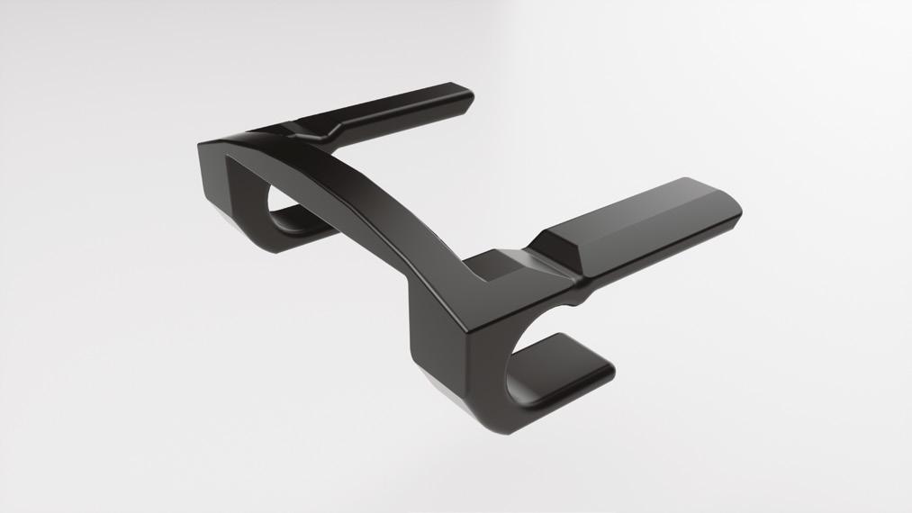
Technical Specifications:
• Stopper device 95°
• Application with Omnia L hinge Crank 0, 8, 15 and Angle 24°÷30°, 45°, 90°
• Made in black plastic
Opening angle stopper
51.LA00.03.0000000 Opening angle stopper 5000 pcs
24
Code Description Packing
Assembly Instruction
14 15 16 17 18 19 20 21 22 23 24 25 26 27 28 29 30 0.1 0.2 0.3 0.4 0.5 0.7 0.8 1 1.2 1.4 1.6 2.4 3.2 4.1 5 5.9 6.8 0.1 0.2 0.3 0.4 0.5 0.6 0.8 1 1.2 1.4 1.6 2 2.8 3.6 4.4 5.3 6.2 0.1 0.2 0.3 0.3 0.5 0.6 0.8 1 1.2 1.4 1.6 1.9 2.5 3.2 4 4.8 5.6 0.1 0.2 0.3 0.3 0.5 0.6 0.8 1 1.2 1.4 1.6 1.9 2.3 2.9 3.6 4.4 5.2 0.1 0.2 0.3 0.3 0.5 0.6 0.8 1 1.2 1.4 1.6 1.9 2.1 2.7 3.4 4.1 4.8 T= A= A= A= A= A= K=3 K=4 K=5 K=6 K=7 95° K T Values given in mm Distance (A) Open 95° Drilling distance (K) Door thickness (T)
Table to determinate the minimum distance A so that a door with T thickness can open without protrusion from the cabinet and without interfering with adjacent doors.
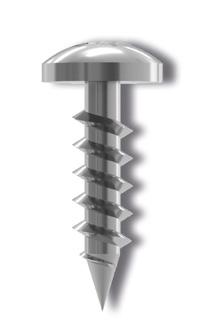
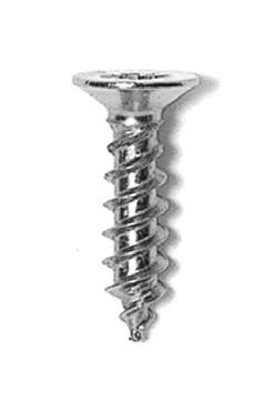
Selftapping screws with countersunk and Pozi drive head, nickel finish, for hinge and mounting plate fixing.
Selftapping screws with Flat and Pozi drive head, nickel finish, for hinge and mounting plate fixing.
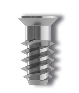
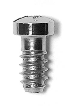
Euro screws with Pozi drive head, nickel finish, for mounting plate fixing.
Euro screws with Pozi drive head, nickel finish, for hinge fixing.
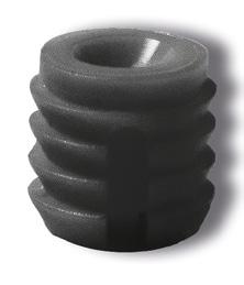
Dowel in nylon for hinge fixing.
Hinge Arm cover cap.
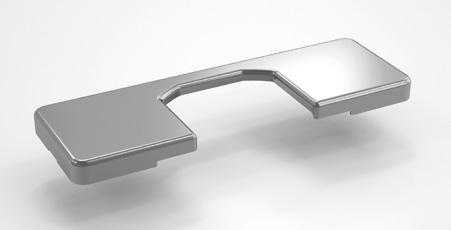
*with Customer logo upon request
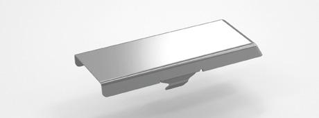
Hinge box cover cap.
Ø Length Material Code 4 12.5 Steel 1A003076015CF 4 15.5 Steel 1A003076025CF Ø Length Material Code 4 12.5 Steel 1A035034150CF 4 15.5 Steel 1A035034250CF Ø Height Material Code 10 12 Nylon 2H011070530CF 8 11 Nylon 2H000449003CF Application Material Code
Crank 0 and Angles Steel 51LM00M90000000 For Crank 8 - 15 Steel 51LM00M90100000 Cup hole distance Material Code I.48 / A.45 / D.52 Steel 51LC00M90000000 Ø Length Material Code 6.3 13 Steel 1A011216009IKCF Ø Length Material Code 6.3 10 Steel 1A075029350CF 6.3 12 Steel 1A075108250CF 6.3
Steel 1A075108150CF
For
14
Accessories
25 H L L L L Ø Ø Ø Ø Values given in mm
HINGES
PLATES Fixing System Fixing System Cup hole distance Angles SELFTAPPING SCREW SELFTAPPING SCREW VELOFIX DOWEL CUP HOLE DISTANCE 48x6 mm CUP HOLE DISTANCE 45x9.5 mm CUP HOLE DISTANCE 52x5.5 mm EURO SCREW EURO SCREW EXPANDING DOWEL DOWEL DOWEL DRILLING DISTANCE 21 mm 21 DRILLING DISTANCE 28 mm 28 DRILLING DISTANCE 37 mm 37 DRILLING DISTANCE 9.5 mm 9.5 DRILLING DISTANCE 12.5 mm 12.5 63.5 48 37 K 6 63.5 45 K 9.5 37 63.5 52 K 5.5 37 26 Values given in mm
Pictograms
MOUNTING
Notes 27
Notes 28
Notes 29
FORMENTI & GIOVENZANA S.P.A. Via Concordia, 16 - 20837 Veduggio con Colzano (MB) - Italy T. +39 (0)362 9471 - F. +39 (0)362 998788 - info@fgv.it - www.fgv.it DISCOVER ALL THE OFFICES IN THE WORLD Edizione 01-2022 EN meneghinieassociati.it