Development requirements for electrical machines to achieve a net zero future


2023
FEMM
Hub ROADMAP REPORt
AutHORs: Michael J Ward 1*, Lloyd Tinkler2 , Xiao Chen3 , Glynn Atkinson4, Leigh Patterson4 , Jill Miscandlon4 , Geraint W Jewell3 , Laura O’Keefe3, Gladys Benghalia4.
1 Department of Electrical & Electronic Engineering, University of Strathclyde, Glasgow, UK


2 Advanced Manufacturing Research Centre, University of Sheffield, Sheffield, UK


3 Department of Electronic and Electrical Engineering, University of Sheffield, Sheffield, UK

4 National Manufacturing Institute Scotland, University of Strathclyde, Renfrew, UK


*michael.ward@strath.ac.uk
Copyright ©2023

First published August 2023
Contact details: The FEMM Hub Roadmap is led by Professor Michael Ward who can be contacted via michael.ward@strath.ac.uk. For any FEMM hub enquires, please contact Hub Manager, Dr Laura O’Keefe L.Okeefe@sheffield.ac.uk.

 FEMM Hub partners and contributors to the roadmap
FOREWORD
The Future Electrical Machines Manufacturing (FEMM) Hub is an internationally leading academic consortium, focused on addressing key manufacturing challenges in the production of high integrity and high value electrical machines. The hub operates across industries, covering the aerospace, energy, high value automotive and premium consumer sectors. Through delivering world-class manufacturing research and innovation, the Hub will assist UK manufacturing to capture significant value in the electrical machine supply chain, improve UK industrial productivity and deliver the environmental benefits and cleaner growth at the heart of the UK’s industrial strategy.
This document summarises work done on our technology roadmap. In developing our roadmap we have taken a net zero CO2 emissions future (as mandated in UK law by 2050) as our destination, and set out to explore what developments in electrical machines manufacture will be needed to get there. There is a commonly held view that large scale electrification of activities which have traditionally been underpinned by the fossil fuel combustion is a central pillar of decarbonization strategy. It therefore seems natural that the FEMM Hub work seeks to understand and describe what this means in terms of electrical machines and how they need to be made in future.
Our work sits alongside other work, focused on the journey to net zero in various industry sectors but provides unique additional insight by focusing specifically on machines (rather than the wider requirements for decarbonization), and by considering needs and implications across sectors. As a research hub, our primary intent has been to use this approach as a basis for identifying the early stage research needs in manufacturing future electrical machines. Inevitably however the problem has many facets and several of the findings that we have identified extend into likely public policy and industrial transformation.
We are delighted to present this analysis and interpretation of the challenges that apply to electrical machines and their manufacture. As with any work on roadmap development this is a snapshot in time based on information we could secure. We aim to maintain and develop this roadmap, and we would be very pleased to hear from you if you have additional information, thoughts, or informed opinions that we should consider as the work develops.
This analysis has been completed based on input from FEMM Hub researchers and partner organisations and we would like to thank those who contributed to the activity with their time and expertise.
Professor Michael Ward University of Strathclyde
the future electrical machines manufacturing hub putting uK manufacturing at the forefront of the electrification revolution
foreward 3 e xeCuTive summary 6 femm Hub roadmap approaCH 8 TeCHnologiCal drivers of CHange 16 performanCe faCTors and improvemenT 26 posiTive sTeps, despiTe unCerTainTy 42 assembling THe roadmap 47 limiTaTions and fuTure work 52 appendix 54
Table of ConTenTs
ExEcutivE suMMARy
The Future Electrical Machines Manufacturing Hub (FEMM Hub) is a UK based manufacturing research programme, established with the aim of putting UK Manufacturing at the forefront of the electrification revolution. That electrification revolution is being accelerated by the global drive towards decarbonisation and the replacement of incumbent combustion based technologies for power generation and transportation with electrically powered alternatives. This transformation is the subject of legislation through the 2019 Climate Change Act, which mandates the transition to net zero by 2050 in the UK.
In this document and the analysis which underpins it, the FEMM Hub investigators, researchers and industrial partners have aimed to explore what this transition to net zero means for future electrical machines manufacture, and to use this time-bound driver as the end point of a roadmap. The transition to net zero creates a set of requirements on the electrical machines industry.
NEED 1: Make machines better so they perform better
NEED 2: Make manufacture more efficient
NEED 3: Secure supply of critical materials
NEED 4: Flexibility and scalability to meet demand
PAgE 6
While it is clear that there are many uncertainties due to the development of future products, business models, and behavioural responses to the net zero challenge, we can begin to articulate a set of issues around material supply and demand and sustainability, which have been initiated by the hub and which need to be extended through future research.
• Post launch of the hub, a cross cutting theme on circular economy was initiated. It is essential that this focus is maintained and embedded across the programme.
• Identifying sector-based demand for electrical machines is subject to large sources of uncertainty, and therefore attempts to determine likely criticalities in terms of material supply is at least equally difficult. There would be value in instigating a focused activity with a view to providing a flexible / dynamic model material supply and demand based on available assumptions.
• Irrespective of the set of planning assumptions made, it seems inevitable that demand for high performance electrical machines is likely to increase aggressively in the coming years. Future manufacturing needs to be capable of dealing with this growth, and of being flexible and adaptable to the uncertainty in demand.
The FEMM Hub roadmap is built on an assessment of technical drivers for potential machine and manufacturing improvements.
The high level improvement factors are as follows:
- POWER AND tORquE DENsity
- HigH EFFiciENcy OPERAtiON
- HigH sPEED OPERAtiON
- REliAbility AND RObustNEss
- sustAiNAblE liFEcyclE
- cOst
This analysis has allowed us to develop a combined future product and future factory model, and to track specific areas of current, planned and required research in a structured manner.
PAgE 7
PAgE 7
OuR ROADMAP APPROAcH
Few would disagree that the challenge of decarbonisation as an urgent mitigation to global climate change is fundamental to the future of our planet. Increased deployment of, and improvements to, electrical machines is an element in this transition. In developing a roadmap for the FEMM hub, we have taken the approach of working back from net zero in 2050 and aimed to explore what this deadline means for electrical machines manufacture.
Our roadmap contents have been developed collectively by the investigators and researchers in the FEMM hub. We have used various public domain documents and academic publications to develop a view of primary drivers of change around electrification. We have also used 1:1 discussion and workshop activity with our industrial members to shape the contents, and in particular provide a definition and interpretation of the major issues that need to be addressed across industry to provide sustainable, useable, and cost-effective solutions for the net zero future.
tHE NEt zERO cOMMitMENt
In June 2019 the UK became the first major economy in the world to pass laws to end its contribution to global warming by 2050. The target requires the UK to bring all greenhouse gas emissions to net zero by 2050, compared with the previous target of at least 80% reduction from 1990 levels1. This implies the need for a combined implementation of zero emissions technology along with a degree of behavioural change. While some reports2 make the important point that a reliance on development and implementation of breakthrough technologies in this timeframe is not realistic, we have taken the view that more extensive use of electrical machines, as a form of established technology, has an important part to play in this transition. Alongside other developments, including the uptake of hydrogen, we believe that enhanced productivity and competitiveness of electrical machines manufacture will play an essential role in enabling net zero.
The transition to net zero and the implications it has on both the performance of, and market demand for, electrical machines form the core focus of the FEMM Hub strategic roadmap. A central part of our approach has been to work back from the net zero future and determine what this means for electrical machines. We aim to do this with consideration of demand for scarce resources in mind, in particular a recognition of the importance of critical elements in magnetic and electrical materials. Through a high level analysis of potential circular economy solutions, we explore alternative routes for the materials both from existing and future machines which could be recaptured rather than wasted, and the potential for life extension options.
2
1 UK becomes first major economy to pass net zero emissions law - GOV.UK (www.gov.uk)
PAgE 8
Allwood, J.M., et al. (2019), Absolute Zero - Delivering the UK’s climate change commitment with incremental changes to today’s technologies, 2019, DOI: 10.17863/CAM.46075
AligNED/AssOciAtED POliciEs
The UK’s Ten Point Plan for a Green Industrial Revolution3 defines the combined objective of building back better (post Brexit and post Covid-19), supporting green jobs, and accelerating the path to net zero. At the time of writing it remains the UK’s main policy directive on the achievement of net zero. The Ten Point Plan is actually a strategy paper, setting out challenges and aspirations rather than providing definition about their delivery in the form of a conventional plan. Nevertheless, it plays an important role is setting out a set of UK ambitions for both climate change action and industrial transformation. Many of the ten points have direct applicability to electrical machines.
For example, “Point 1: Advancing offshore wind” outlines the intentions of the UK government to “quadruple the offshore wind capacity,” which will see a rapid increase in the number of turbines in our seas. In fact, the government intends to create enough green energy by 2030 to power all homes, and by 2035 to have an entirely decarbonised grid4 , of which wind power is a major component. However, turbines themselves are increasing in size, with generators weighing multiple tonnes, meaning the through- and end-of-life management of these materials and components will be critical to reducing wastage of critical elements. According to studies, generator failures account for between 12% and 16% of overall turbine failures annually, of which repairs or replacements account for significant proportions of turbine downtime and cost5,6
With regards transportation, “Point 4: Accelerating the shift to zero emission vehicles” outlines a ban on the sale of new petrol and diesel cars and vans in 2030, and of hybrid cars and vans in 2035. Whilst there are alternatives being brought to market (hydrogen powered vehicles, for example), the Ten Point Plan is heavily centred on electric vehicles, all of which will require electrical machines. This sentiment is echoed in “Point 5: Green public transport, cycling and walking”, which outlines plans for electrified rail and bus networks. Whilst “Point 6: Jet zero and green ships” primarily focuses on sustainable aviation fuels and hydrogen fuel cell powered aircraft, there is also work going on in industry exploring the potential for electric aircraft also7
Finally, “Point 10: Green finance and innovation” is committed to investing in R&D to grow UKled decarbonising technologies and innovations. It also intends to mandate reporting on climaterelated finances by 2025. What it doesn’t specifically mention is the gap in development of a circular economy for products. This gap includes the increased value in growing the recycling/remanufacturing industries, increasing jobs, and reusing materials, reducing reliance on depleting virgin stock which is subject to market fluctuations and supply risk.
It is clear that the UK plans to achieve net zero and succeed in the “green industrial revolution” are heavily reliant on emerging and developing electrification technologies, including the use of electrical machines. Ensuring that the sustainable supply of these is able to meet the demand is critical.
Figure 1 summarises how UK public funding has been apportioned between sectors. In some ways this can be seen as a proxy indication of the government importance that has been assigned to decarbonisation of major sectors and activities.
Well over half of the apportioned funding is aligned to sectors where electrical machines play a central role in enabling the transformation. Some of these interventions represent ongoing funding of long-
3 https://www.gov.uk/government/publications/the-ten-point-plan-for-a-green-industrial-revolution
4 https://www.gov.uk/government/news/plans-unveiled-to-decarbonise-uk-power-system-by-2035
5 Carroll, J: McDonald, A; McMillan, D. (2019). Failure Rate, Repaire Time and Unscheduled O&M Cost Analysis of Offshore Wind Turbines. Wind Energy, 19 (6). pp 1107-1119. ISSN1095-4244;
6 Artigao et al. (2021). Failure Rate and Downtime Survey of Wind Turbines Located in Spain. IET Renewable Power Generation, 15 (1). Pp 225-236.
7 https://www.hie.co.uk/support/browse-all-support-services/net-zero-scotland/netzerotransport
PAgE 9
Public tRANsPORt £9bN +
• Billions of pounds in enhancements and renewals of the rail network

• £4.2 bn in city public transport and £5 bn on buses
• £120m to introduce British Built ZE buses
ENERgy suPPly AND DistRibutiON £7.7bN +
• HMG committed 20% stake in Sizewell C £4bn
• £1.7bn to take three nuclear sites to FID
• £385m in Advanced Nuclear Fund enabling £215m in small modular reactors, unlocking £300m of private sector match. £170m R&D in AMRs
• £40m in developing the regulatory frameworks and supporting UK supply chains
• £160m into modern ports and manufacturing infrastructure for offshore renewables
• £240m Net Zero Hydrogen Fund
• £184m for new fusion facilities, infrastructure and apprenticeships
MARitiME £206M
• DfT UK Shore £206m
• Includes £20m Clean Maritime Demonstration Programme
• Investments to harness the UK’s research and innovation excellence to decarbonise maritime
• £77m Zero Emission Vessel and Infrastructure (ZEVI) competition

• £7.4m flagship UK National Clean Maritime research hub
AutOMOtivE £6bN
• APC £1bn 10 yr funding (50:50 split HMG:UK Auto Council)
• £1.3bn to accelerate the roll out of charging infrastructure
• Transitioning to zero emission cars and vans: 2035 £2.8bn

• Up to £1bn to support creation of a Gigafactory
• £582m to extend the Plug-in Cars to 2022–23
• £20m across trials of zero emission heavy goods vehicles
Public sEctOR cONsuMPtiON £1bN
• Public Sector Decarbonisation Scheme £1bn
bEHAviOuR cHANgE £2bN
• Active travel initatives £2bn
ENviRONMENtAl REMEDiAtiON £6.5bN
• Our £1bn Carbon Capture Usage and Storage Infrastructure Fund
• £40m second round of the Green Recovery Challenge Fund
• £5.2bn in a six-year programme for flood and coastal defences
• £100m investment in brandnew Greenhouse Gas Removals including Direct Air Capture
• £100m for Energy Storage and Flexibility innovation challenges
iNDustRiAl cONsuMPtiON £170M
• Industrial Decarbonisation Challenge £170m
DOMEstic cONsuMPtiON £1bN
• £1bn to extend green home measures
gREEN FligHt £715M
• ATI £685m
• £15m into FlyZero
• £15m SAF competition
term industrial innovation support mechanisms, such as The Aerospace Technology Institute (ATI), and Advanced Propulsion Centre (APC).

The ATI creates the technology strategy for the UK aerospace sector and funds world-class research and development. According to ATI, in 2019, aviation contributed around 3.5% to global warming
10
PAgE
Figure 1 - UK Public funding for decarbonisation split into major sector beneficiaries
stARs iNDicAtE substANtiAl ElEctRicAl MAcHiNE RElE vANcE
through carbon dioxide (CO2), nitrogen oxides (NOX) and contrails. Without adoption of lower carbon technologies, aviation will contribute to 38 gigatonnes (Gt) of CO2 emissions to 2050, representing 9.5% of the total global carbon budget to limit global warming to 1.5°C of pre-industrial levels8 . Development and adoption of sustainable aircraft technologies and improved operations as assumed in ATI’s future market scenario would enable global carbon emissions to be reduced by nearly 2.5 Gt by 2050. Zero-carbon emission aircraft technologies have the largest potential for reducing carbon emissions at the tailpipe for the future. It should remain a top priority to accelerate the adoption of zero-carbon aircraft to have the greatest impact by 2050 and ensure the UK is a leader in their development for a greater economic benefit.
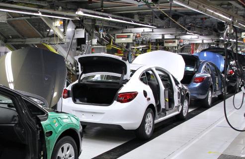
The APC collaborates with UK government, the automotive industry and academia to accelerate the industrialisation of technologies, supporting the transition to deliver net-zero emission vehicles. Its role is to help accelerate the transition to a net-zero automotive industry. APC have identified three primary areas of challenge: the dependency on magnets from China, the serviceability and disassembly challenges from greater integration with driveline components and power electronics and the environmental considerations on raw material extraction, processing and re-use.
The FEMM hub compliments this existing landscape by focusing on early Technology Readiness Level (TRL) research into electrical machines and their manufacture which could be deployed into industry through those bodies. Therefore, in contrast to the industry-specific bodies, the FEMM Hub has a role in both technology -pull and -push; addressing longer term industrial challenges and in developing emerging technologies which are applicable across sectors.
The UK also benefits from major innovation focused organisations serving the needs of important industries which will rely on development of electrical machines to drive net zero aspirations. Again, through their work these organisation provide insight into the technological needs and barriers to be overcome on the journey to net zero. Driving the Industrial Revolution Industrialisation Centres (DER-IC) are the gateway to a network of world class design, manufacturing, test and validation capabilities across the UK. DER aims to support the UK’s push towards a net-zero carbon economy and contribute to the development of clean technology supply chains, worth £80 billion in gross domestic product by 2050. DER has established a number of regional innovation centres, including the Power Electronics and Electrical Machines Centre at Nottingham, which incorporates a Future Factory for High Performance Electrical Machines. In principle this provides an ideal mechanism to support scale-up and translation of FEMM Hub research. The Offshore Renewable Energy Catapult (OREC) – OREC is the UK’s leading technology innovation and research centre for offshore renewable energy. It plays a key role in delivering the UK’s net zero targets by accelerating the creation and growth of UK companies in the offshore renewable energy sector. OREC has identified particular challenges related to anticipate growth fleet of wind turbines deployed in Scotland and associated end of life issues9:
• Current capacity- 3.5 GW of installed capacity, from 432 turbines
• Authorised consent (additional capacity to current, online from 2024 to 2029) - 6.6 GW installed capacity, from 484 turbines
• By 2050, it is estimated that to achieve the expected growth of offshore wind it will require approximately 14.7 million tonnes of steel, 8.36 million tonnes of concrete, 1.54 million tonnes of ductile iron casting, 93 thousand tonnes of neodymium, and 67 thousand tonnes of copper
• Decommissioning: over 3.8 GW of offshore wind capacity in the UK is expected to reach the end of its operational life by 2035. The estimated number of units ready for decommissioning will be
PAgE 11
ATI, Destination zero – The Journey to 2050
8
9 FINAL-Catapult_ELMWind_Report-online-version.pdf
5,400 by 2066 for the UK and 1,340 for Scotland.
iNtERNAtiONAl Pl AyERs
While the FEMM Hub is a UK entity, and strongly influenced by UK policy and approaches, it is clearly essential to consider from various agencies are shown in Figure 2 and Figure 3. Figure 2 shows these on a timeline and Figure 3 shows these zero by 2050 presents some very serious challenges. While most of these clearly fall outside of the scope of the FEMM Major technological expectations include the provision of alternative magnet materials, commercially available superconducting
Beyond these direct expectations is the wholesale growth in renewable energy provision, the assumption that this underpinning supply chain and circular economy challenges.
PAgE 12
10Electric Motors Research and Development | Department of Energy 11Electric Motor Thermal Management | Transportation and Mobility Research | NREL 12 KIT - KIT - Media - Press Releases - Archive Press Releases - Research for Agile Production of Electric Motors
Figure 2 - Major policy events and
consider developments and approaches at the international level. Major elements of legislation, policy, and projections these ranked by importance and the difficulty associated with them. It is very apparent that the intent to achieve net FEMM Hub, there are some explicit and implicit assumptions on the availability of technology to enable the change. superconducting motors, next generation e-steels, and alternative winding methods.
this can be provided at a level that matches the demands of an increasingly electrified transportation system, and the
PAgE 13
and
timeline
projections
• Recognise different requirements of different parts of the sector eg HGV, Light commercial, passenger cars, moped
Security of supply
• • No Domestic e-steel supply
Recycling of materials might be possible in UK, but no production or assembly
•
Cheaper to scrap machines than to recover materials
2037: APC anticipate transition to fully recyclable magnets elimination of wet processes •
Motor volumes for all electric aircraft (not just propulsion needs) not currently reflected
•
• Potentially very limited / restricted supply of some REE
•
• 2025: HMG target to double number of cyclists from 2013
• 2035: HMG target renewables powering entire grid
• 2030: ATI anticipate: superconducting motors in the market Carbon nanotube and ceramic insulated wiring in motors Additive manufactured parts and introduction of FeN magnets
• Reluctance to open new mines for REE in UK / EU due to environmental concerns
• Linking customisation with reconfigurable manufacturing capabilities
e ssent I al to take act I on before I ssue of femm Hub r
Important I ssue, to be addressed by roadmap I f data / I nfo can be obta I ned
Important
• High cost in changing production line
• Closing the ML / AI gap with certification / verification
• Cost effective and speedy additive manufacture
• 2040: APC anticipate advanced cooling systems to be standard next generation e-steels
• No European rare earth element supply
• No current supply for reman of electrical machine components
net zero 2050
roblemat I c area, but not of major concern to roadmap, or out of scope
mI nor I ssue, I ncorporate I f somet HI ng wort H w HI le can be added
• Workforce
• Challenges in more integrated design
• Increased automation of highly adaptive / varied manufacturing processes (typically done manually)
•
• Urban air mobility is really uncertain. Projecting volumes –how to begin?
• Simulation and evaluation of performance at system levelneed multi-variable optimisation design tools
•
2025: APC anticipate resurgence of alternative magnetic material usage instead of NdFeB
• 2050: HMG aim all cars / LGVs / HGVs are battery or fuel cell based small regional services electrical, modest proportion hydrogen (500-100 mile range)
2030: UK Ban on sale of new petrol / diesel cars and vans
• How does this help?
• Volumes
• Manufacturing barriers
PAgE 14
Figure 3Electrical machines policy drivers leading up to
oadmap
p r I or I t I sat I
I
t H
p
on of
mprovements
emes
p roblemat I c
AND POlicy l ANDscAPE – ‘sO WHAt?’ AssEssMENt
WitHiN tHE FEMM Hub scOPE, and based on high level information, the roadmap for future electrical machines needs to address four key areas of need:
NEED 1: The provision of step change technologies for both machine performance and manufacturing resource efficiency.
NEED 2: Making machines better to perform better.
NEED 3: Materials supply, potential replacement for scarce materials, and enablement of a circular economy approach which supports anticipated market growth with known limits to availability and capacity of materials.
NEED 4: The ability to support radical growth in demand for certain classes of product, component and material, coupled with substantial uncertainty over the magnitude of that growth.
These areas of need represent the primary output of high-level analysis of the net zero commitment and associated policy landscape in the context of electrical machines.
bEyOND tHE FEMM Hub scOPE, it would be beneficial for the various stakeholder groups to:
- Explore global regulation of scarce materials including rare earth elements, with a view to prioritising use on the demanding applications
- Establish a recognised analysis of the electricity supply and demand impacts of wholesale electrification of transportation systems
- Trigger applied research into superconducting machines, and enhanced machine – system integration.
PAgE 15 NEt zERO
tEcHNOlOgicAl DRivERs OF cHANgE
tEcHNOlOgy Pl ANNiNg FOR AN uNcERtAiN FutuRE
The policy landscape surrounding net zero, as summarised in Figure 2, provides a useful structure of targets and requirements over time. A logical next step could be to work back from these requirements, prioritise actions and develop a plan which delivers against these needs. However, we have noted that several of the policy requirements and targets are problematic, in some cases because the requisite technology does not yet exist. Further uncertainty arises in attempting to predict market drivers in the face of emerging applications such as urban air mobility, and disruptive technologies such as autonomous driving which may influence the ownership thus demand for electric vehicles. Consequently, detailed planning and large scale of provision and implementation of specific technologies is problematic. Our response to this is to instead develop a roadmap based on several principles:
1. tHE NEED FOR FlExibility iN Pl ANNiNg
2. iDENtiFyiNg sOlutiONs WitH bROAD APPlicAbility
3. Pl AcE A cONtiNuED EMPHAsis ON tRAckiNg FutuRE tRENDs iN POlicy, iNDustRy, AND REsEARcH AND PROActivEly sEEkiNg Out OPPORtuNitiEs WHicH HElP ADDREss tHE NEt zERO cHAllENgE
4. ENgAgE WitH iNDustRiAl cliENts AND MEEt tHEiR NEEDs WHERE POssiblE
tHE NEED FOR FlExibility iN Pl ANNiNg
Planning for any long-term goal, such as the achievement of net zero by 2050, requires a series of assumptions to be made. For the FEMM Hub, our main purpose in thinking forward to 2050 is to understand what the future needs will be in terms of the capability and performance of electrical machines, and in terms of the required production volumes, supply chains, serviceability and through life implications of this quantity of machines. As we have already stated, however, there are major areas of uncertainty.
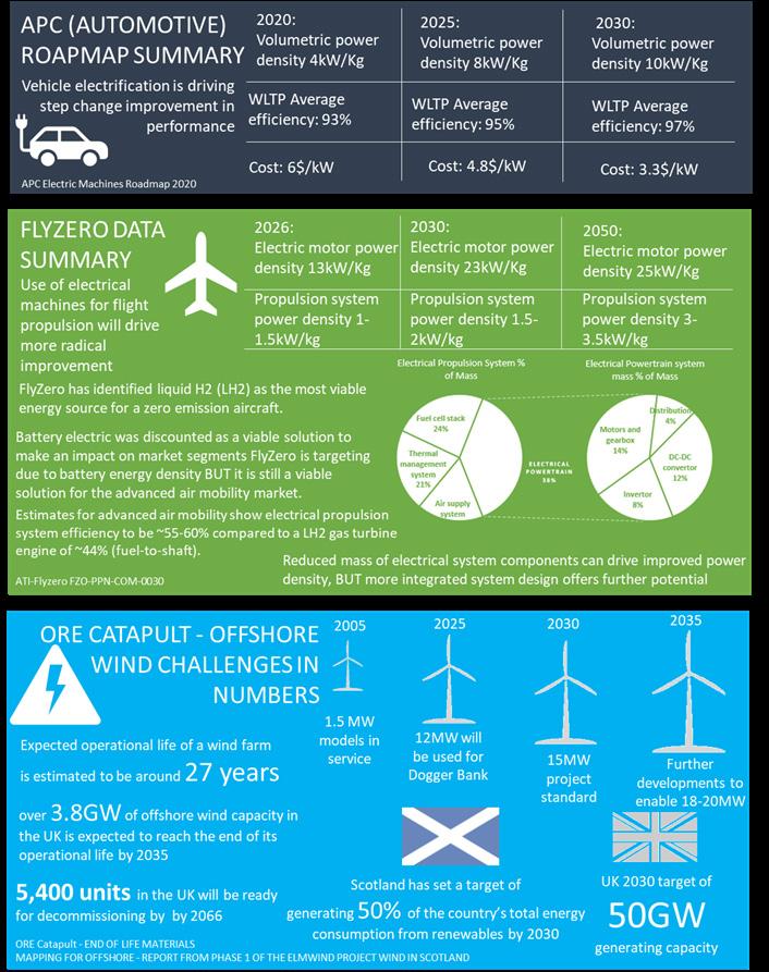
If we take aerospace applications, and the transition to net zero flight as a case in point, the ATI has developed and evaluated concepts for net zero flight and aircraft architecture. Flyzero13 has identified liquid hydrogen as the most viable energy source for a zero emission aircraft. The Flyzero team assessed a hydrogen fuel cell powered electrical propulsions system, identifying that the power density of the system would be the primary parameter to optimise. Initial assessment showed that an electrical propulsion system would be significantly heavier than a gas turbine equivalent, however, it
13 https://www.ati.org.uk/flyzero/
PAgE 16
was an unexplored area with significant potential for improvement.
Under this configuration, system level optimisation is of key importance, with 14% of that overall propulsion system coming from the motor and gearbox. Table 1 indicates both the system level improvement required and a breakdown into modules, including the electric motor which requires ultimate power density target of 25 kW/kg by 2050, with 23 kW/kg in 2030 and 13 kW/kg in 2026. The current view therefore seems to be that gas turbines, powered by a combination of hydrogen and synthetic fuel will be the dominant propulsion system for midsize and larger aircraft. Electrical machines, powered by hydrogen fuel cells in the case of regional aircraft and by batteries for smaller craft appear to be the more likely configuration. In Table 1 we have taken the most recent projections of market size from ATI of the size of the aviation market in 2050, segmented them and taken assumptions from ATI documents on these likely propulsion configurations.
These figures only deal with electrical machines as the primary source of propulsion. They do not consider the many other uses of electrical machines in ancillaries and actuation. Electrical actuation has increased in the Boeing 787 and Airbus A350 generation of airliner and will continue in replacing
14 FZO-CST-REP-0043-Market-Forecasts-and-Strategy
15 Flying cars: How air taxis will revolutionise the way we travel | BBC Science Focus Magazine
16 https://www.esru.strath.ac.uk//EandE/Web_sites/17-18/paradigmev/number-of-cars-projections.html#:~:text=It%20was%20extended%20this%20 average,the%20nowadays%2031%20million%20cars.&text=The%20Business%20as%20Usual%20is,in%20the%20road%20for%202050. < projected vehicle numbers by 2050 and changes required to achieve these scenarios
PAgE 17
Table 1- Consolidation of ATI market growth and Flyzero evolution change for primary propulsion across aerospace market segments
Assumed 2050 net zero propulsion configuration Number of aircraft in service [1] Number of aero propulsion machine in service* Production volume (aircraft)10 Production volume (machines)* Freighters Synthetic fuel/ hydrogen powered gas turbines 6,070 0 1,600 0 Widebody Synthetic fuel/ hydrogen powered gas turbines 4,310 0 1,990 0 Midsize Split between LH2, Combustion (Flyzero FZM Concept) 6,520 0 3,100 0 Narrowbody LH2, Combustion, Turbofan (Flyzero FZM Concept) 40,820 0 18,040 0 Regional LH2 Fuel cell powered 6x electrical machines (Flyzero FZR Concept) 6,910 41,460 2,950 35,400 Subregional Battery powered 2x electrical machine 4,460 8,920 2,540 5,080 TOTALS 69,090 50,380 30,220 40,48014
pneumatic systems due to reduced weight and more efficient propulsion resulting from reduced need for engine offtake. Recent aero architecture has driven an increase in the reliance on electrical machines for these purposes; a trend which looks likely to continue. Moreover, there is a realistic prospect that the industry will be disrupted by the emergence of short range, and potentially autonomous, urban transport air vehicles – so called “air taxis”. This would be a new market, which could potentially dwarf conventional aviation. Analysts at Morgan Stanley expect the global air taxi market to be worth £2.7tr by 205015 .
Despite the fact that the FEMM Hub is not primarily concerned with mass market automotive applications, the size and nature of the automotive sector and its use of electrical machines is essential data in planning the manufacturing needs for higher demand machines. This is on the basis that, unchecked, the automotive sector is likely to consume significant proportions of global material availability and supply chain capacity and this will form a constraint on what is available to FEMM hub supported sectors. Data and segmentation on automotive electrical machine demand is taken from Automotive Council and APC market data16. As with the aerospace sector, the automotive sector is also potentially subject to major disruptive change, with market analysis predicting future new ownership models, enabled by vehicle autonomy, to radically alter the mix of car ownership in favour of pay-per-use models. Such a change could drastically disrupt the overall size of the market and the number of cars in operation.
Figures 4 and 5 try to illustrate the scale of challenge in terms of supply, technical and uncertainty which faces the electrical machines industry as it prepares for a net zero future. In Figure 4 extracts from high level public domain assessments of product, market and materials demand are summarised. Figure 5 assembles of the technical change expectations as predicated ATI, APC and ORE Catapult for their respective sectors. As we have noted, however, there are significant areas of uncertainty in terms of needs, product responses and business models that will support the transition.
Uncertainty of this type is typical of any industry when an attempt is being made to project forward almost 30 years. In the development of electrical machines, it is reasonable to expect an unusually aggressive pace of change and potential market disruption, as described previously. Whilst there is a level of uncertainty in analysis there are some clear overarching SUPPLY CHAIN RESPONSES to this uncertainty, including:
REsPONsE 1: Step-change improvement in production volume for high performance applications
REsPONsE 2: Flexibility in physical supply chains and in the product development process
REsPONsE 3: New circular economy provisions to support material availability under increased volume
REsPONsE 4: And, especially to enable market disruption,
substantial cost reduction
One of the key implications of the likely growth in electrical machine use, especially in high demand applications, and the large error bounds on any prediction, is that of supply chain risk. Electrical machines make use of materials, some of which are scarce. The potential for substantial growth in demand, especially for high demand applications such as flight has the potential to create an imbalance between supply and demand.
17 The Role of Critical Minerals in Clean Energy Transitions – Analysis - IEA
18 European Chemical Society, “The Periodic Table and Us: It’s History, Meaning and Element Scarcity,” 22 Jan 2019. [Online]. Available: https://www. euchems.eu/periodic-table-and-us/. [Accessed 25 Jan 2023].
19 Centre for Sustainable Systems, University of Michigan, “Critical Materials Factsheet,” 2021.
20 S. M. Hayes and E. A. McCullough, “Critical Minerals: A Review of Elemental Trends in Comprehensive Criticality Studies,” Resources Policy, pp. 192199, 2018. DOI: 10.1016/j.resourpol.2018.06.015.
21 Hurd et al. (2012). Energy-Critical Elements for Sustainable Development. Materials Research Society, 37. Pp405-410.
22 Fears, P. (2017). Electric Vehicles Drive Up Rare Earth Magnets Prices. www.bunting-berkhamsted.com
PAgE 18
HM Government 10 point plan for a Green Industrial Revolution - Point 1: advancing offshore wind HMG intend 4x current offshore wind capacity
Analysts at Morgan Stanley expect the global air taxi market to be worth £2.7tr by 2050

Based on ATI market growth predictions, and Flyzero assumptions on net zero propulsion 11,370 regional and sub-regional aircraft with electrical propulsion by 2050

Wood Mackenzie predict 700 million electric vehicles on the road globally by 2050, with annual sales of 62 million
Offshore Renewable Energy Catapult have estimated that by 2050, that to achieve the expected growth of offshore wind it will require approximately 14.7 million tonnes of steel, 8.36 million tonnes of concrete, 1.54 million tonnes of ductile iron casting, 93 thousand tonnes of neodymium, and 67 thousand tonnes of copper


Development and adoption of sustainable aircraft technologies and improved operations as assumed in ATI’s future market scenario would enable global carbon emissions to be reduced by nearly 2.5 Gt by 2050
The UK Driving the Electrical Revolution Industrial Strategy Challenge Fund was established to support the UK’s push towards a net- zero carbon economy and contribute to the development of clean technology supply chains, worth £80 billion in gross domestic product by 2050

PAgE 19
Figure 4 - Electrification growth challenge in numbers
RARE E ARtH ElEMENts
The complex alloys required for high value electrical machines components are reliant on a number of rare earth (REE) and other elements, some of which are at risk of natural depletion due to the rate in which they are being mined. For example, global demand for critical materials for batteries - e.g. cobalt, lithium and other REEs also critical for electrical machines - is anticipated to increase by 6-13
23 https://tradingeconomics.com/commodity/neodymium
PAgE 20
Figure 5 - Technical challenge in numbers
24 Chia, K; Murtaugh, D; Burton, M. (2021). Silicon’s 300% Surge Throws Another Price Shock at the World. www.bloomberg.com
Component Part Material(s) of Interest
NdFeB Cobalt, Dysprosium
Niobium, Neodymium, Boron
Magnets
SmCo Cobalt, Hafnium Copper, Zirconium
Aluminium, Cerium, Gadolinium, Iron, Praseodymium
Iron, Praseodymium, Samarium
Windings
Copper
Rotor Core Carbon steel alloys
Copper
Manganese, Phosphorous
Iron, Silicon, Sulphur
Silicon steel Chromium, Cobalt Manganese Iron, Silicon
Stator Core
Steel alloys
Manganese, Niobium, Phosphorous, Vanadium, Nickel
Iron, Silicon, Sulphur
times by 204017, with the majority of these materials being mined in China. Table 2 shows the common alloys required in high value machines, and the individual elements relative supply threat level in line with criticality research in recent years 18 19 20 .
With demand comes increased prices, some of which have already been seen. Neodymium (found in the magnets) had a seven-fold increase in price between 2009 and 2011 following a reduced quota announcement from China, who produce 95% of the world’s neodymium supply 21 22, and thus hold a monopoly. Whilst prices did reduce drastically the following year, they have been gradually increasing since 2016, with a rapid increase going into 202223. Silicon (used in the steels in electrical machines) has also seen a 300% increase in price in 2021 caused by reduced production in China24. Both of these examples serve to demonstrate instability in the market not only from an economic perspective but also the supply risk which has the potential to halt production of future electrical machines, directly impacting on consumers, industries and climate targets. In addition to increasing demands and decreasing supplies, recent events, such as the COVID-19 pandemic and Russian invasion of Ukraine, have highlighted the precarity and risks in the global supply chain for the UK with its reliance on external sources. In response to this, the UK Government laid out plans to mine and refine material domestically, and establish a circular economy to reduce dependence on external markets25
For the Hub, this supply risk provides clear motivation to develop manufacturing processes that minimise material waste in production; develop machines or materials that make better use of critical elements (e.g. use of grain boundary diffusion magnets); and design for material recovery.
Perhaps most significantly the hub has added a global challenge on the circular economy, which was not part of the original scope of the hub. The importance of circular economy issues are outlined in Spotlight 1.
25 https://www.gov.uk/government/publications/uk-critical-mineral-strategy/resilience-for-the-future-the-uks-critical-minerals-strategy
PAgE 21
Table 2 - Alloys and elements deployed in electrical machines, and availability status
Increaseed threat to supply Limited availability Not currently threatened
Current end of life practices for electrical machines are varied, and are, on the whole, not sustainable. For higher value machines, rewinding is often undertaken multiple times throughout the life of the machine to extend the asset life. Through-life monitoring of machines is becoming more common, with retrospective implementation of sensors assisting in the decision-making process of preventative maintenance. However, when the asset does finally come to the end of its life, electrical machines are often shredded, burned, or placed in landfill, which are not sustainable options for the longer term.
Circular economy principles should not be considered as a single solution, but an array of options which can assist with improving the sustainable credentials of a product throughout its life cycle. The principles can be ranked in a hierarchy based on the most to least favourable solutions as shown in Figure 6. For example, redesigning a component- to require less material and energy consumption during manufacture and with the end-of-life management in mind- is a solution which is further up the hierarchy than maintaining a current, non-optimal design and simply recycling the material at the end of its life. Recycling has an important role to play in the circular economy but is still very energy intensive and other principles such as reuse and refurbish / remanufacture should be prioritised. However, recycling could play a key role when dealing with machines currently in use, as these have not necessarily been designed with end of life in mind.
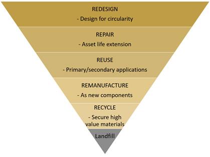
Implementing circular economy principles in future electrical machines will provide opportunities to design for disassembly, recirculation of components, and use in secondary applications. Since the circular economy is an overarching framework which provides solutions for complex systems, there is a wide variety of techniques available which can be used to optimise individual situations, and the working timescales could dictate how solutions are implemented. Key areas of future research focus include:
- sustAiNAblE manufacture through removal of high energy processes and single use components
- Design of REcOvERAblE cOMPONENts including copper, electrical steel, and magnets
- sOlvENt AND ADHEsivE FREE motors through advancements in manufacturing solutions
PAgE 22
sPOtligHt 1: tHE ciRcul AR EcONOMy MAcHiNEs
Figure 6 - Hierarchy of Circular Economy Principles
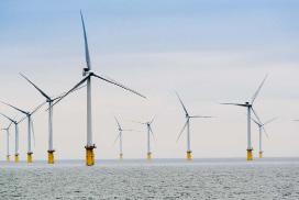
cAsE stuDy 1: WiND ENERgy sEctOR
Consider the wind sector as an example. It is projected that by 2035, approximately 800-900 offshore and 1700 onshore wind turbines will be decommissioned within the UK26 27. A typical 3 MW wind turbine contains approximately 4.7 tons of copper, 3 tons of aluminium, and 2 tons of rare earth elements28 which will need to processed in a sustainable way. In addition, the UK set out plans to increase offshore wind capacity to 40 GW by 2030 and 100 GW by 205029 , requiring larger scale assets in greater quantities. These wind turbines have not had the final design locked down yet, due to the continual development of output per asset. The wind turbine generators currently in service were not designed for disassembly and end of life processing, but intelligent solutions will still need to be found in order to recirculate the key materials within them. On the other hand, there is a huge opportunity to implement circular economy principles today which will lead to a more optimal end of life for the next generation of turbines.
26 Spyroudi, A. (2021). End-Of-Life Planning in Offshore Wind. Offshore Renewable Energy Catapult. www.ore.catapult.org.uk
27 Zero Waste Scotland. (2021). The Future of Onshore Wind Decommissioning in Scotland. www.zerowastescotland.org.uk
28 https://www.worldbank.org/en/news/infographic/2019/02/26/climate-smart-mining
29 The Climate Change Committee. (2020). The Sixth Carbon Budget. https://www.theccc.org.uk/publication/sixth-carbon-budget/
30 https://www.statista.com/statistics/715421/tesla-quarterly-vehicle-production
PAgE 23
iDENtiFyiNg sOlutiONs WitH bROAD APPlicAbility
In general we can see a drive for radical change in the performance of the future electrical machines value stream development we have undertaken brainstorming and ideas ranking activity on key manufacturing barriers. This unstructured electrical machines needed to underpin the transition to net zero. These have been collated through workshop activity commonly occurring, and highest ranked areas of this diagram we can see common issues spanning:
- The role of data in supporting through-life decisions
- Standards for products including end of life
- Implications on dwindling resources.
Prioritisation of imProvements
PAgE 24
Figure 7 - Headline electrical machines manufacturing
Data Driven manufacture ProDucts anD stanDarDs future factory neeDs Process technology suPPly of resources enD of life/ reProcessing 2020 2030 Gap in manufacturing technology at lowmedium volume prevents scale up No domestic rare earth element supply Speeding up integration of new technology / AI into manufacturing processes Simulation and evaluation of performance at system level - need multi-variable optimisation design tools Supporting business expansion for manufacture scale-up Cheaper to scrap machines than to recover materials Alternative to encapsulation processes Variability in quality No current standardisation of components High cost in changing production Quality procedures for product tracking Cost effectiveness of processes for mass manufacture Security of supply No current supply for remain of electrical machine components Anchoring supply Workforce No domestic e-steel supply No European rare earth element supply Quantity manufacturing effect on machine performance Lack of skilled workforce in EMs Recycling of materials might be possible in UK, but no production or assembly Uncertainty on topology changes in future No clarity on production volumes How to produce repeatable, reliable product No clear understanding of requirements (automation/robotics) for remanufacture, recycle, repair No government directives on reuse/remain/recycle of EM - need something similar to battery initiative No clear understanding of manufacturing requirements for the future
stream especially in relation to volume capability, flexibility, product performance and cost. As part of the roadmap unstructured activity identified a number of high level manufacturing challenges related to the anticipated need for activity with the FEMM Hub investigators, researchers and in industrial partners in Figure 7. Summarising the most
rovements themes
Linking shop floor data with predictive outcomes along future assembly
Shop floor optimisation for end of life activities (remain, recycle, repair)
Manufacturing barriers
Closing the ML/AI gap with certification/verification
Increased automation of highly adaptive/varied manufacturing processes (typically done manually)
Challenges in more integrated design
Linking customisation with reconfigurable manufacturing capabilities
Role of data in informing throughlife decisions
Difficulty keeping up with demand targets within industry
Current crimping processes not energy efficient
Research capacity in manufacturing
Reluctance to open new mines for REE in UK/EU due to environmental concerns
Standards for products including end of life likely to impact factory and supply chain options
Process interdependencies not fully understood
Cost effective and speed additive manufacture
Potentially very limited / restricted supply of some REE
Implications of dwindling resources on process technology requirements
manufacturing challenges associated with achieving net zero
PAgE 25
2030 2040 2050
production line Scrappage
DRivERs OF cHANgE – ‘sO WHAt?’ AssEssMENt
WITHIN THE FEMM HUB SCOPE, there are a number key points which need to be built into our planning of future research based content:
- Post launch of the hub, a cross cutting theme on circular economy was initiated. It is essential that this focus is maintained.
- Identifying sector-based demand for electrical machines is subject to large sources of uncertainty, and therefore attempts to determine likely criticalities in terms of material supply is at least equally difficult. There would be value in instigating a focused activity with a view to providing a flexible / dynamic model material supply and demand based on available assumptions.
- Irrespective of the set of planning assumptions made, it seems inevitable that demand for high performance electrical machines is likely to increase aggressively in the coming years. Future manufacturing needs to be capable of dealing with this growth, and of being flexible and adaptable to the uncertainty in demand. This overarching need for flexibility and adaptability is summarised in the following supply chain responses:
REsPONsE 1: Step change in production volume for high performance applications
REsPONsE 2: Flexibility in physical supply chains and in the product development process
REsPONsE 3: New circular economy provisions to support material availability under increased volume
REsPONsE 4: And, especially to enable market disruption, substantial cost reduction
BEYOND THE FEMM Hub scope, it would be beneficial for the various stakeholder groups to:
- Instigate research programmes into alternatives to scarce rare earth elements
- Establish a global working group aimed at long term planning for this global resource challenge
PAgE 26
PERFORMANcE FActORs AND iMPROvEMENt
Despite the uncertainty we can be confident that step change improvements are needed in various aspects of product, manufacturing and supply chain performance that are likely to make up the solutions for 2050. These are in the following areas:
• Power and torque density
• High efficiency operation
• High speed operation
• Reliability and robustness
• Sustainable lifecycle
• Cost.
Figure 8 shows the raw output of workshop activity involving FEMM Hub researchers and industrial partners. While the outcome of this process is difficult to read in detail, it clearly illustrates the complexity and interplay between the performance factors, and various underpinning technological opportunities. In future iterations of this roadmap we will use this map of relationships and connections to help assess which areas of research and development have the potential to impact multiple performance factors, and therefore how we can maximise the impact of research. The aim was to provide a consolidated map of options and improvement areas associated with these performance factors. The relative importance of these factors will clearly vary from application to application, but the holistic position is valuable in outlining common areas of research focus. This rather complex view has been developed from workshop activity on each of the six performance factors, and these individual analyses are provided in the appendix (see page 54).
POWER AND tORquE DENsitiEs
High power and torque densities are preferable for high value electrical machines in aerospace, energy, high value automotive and premium consumer applications. Whereas the power and torque densities of an electrical machine can be improved by various means, this roadmap focuses on the techniques relevant to manufacturing aspects. Note that power density is proportional to the machine operation speed while the torque density is not. Hence, high speed operation will be discussed in a separate section and this section includes the manufacturing related techniques for reduced structural weight, higher magnetic loading, higher electric loading, and improved thermal management.
PAgE 27
cAsE stuDy 3: EFFEcts OF REDucED stRuctuRAl WEigHt ON POWER AND tORquE DENsitiEs
Although the majority of R&D effort in electrical machines is directed towards the active electromagnetic elements, the power and torque densities of an electrical machine are strongly influenced by the mass of the non-active structural elements, e.g. shaft, rotor hub, bearings, casing, connectors or terminal boxes etc. A reduction in structural weight of an electrical machine through a combination of material selection and geometric optimisation offers a productive and often under-utilised route to significantly enhancing power density. A key factor in this regard is the proportion of the overall mass which is contributed by the non-active and opposed to the active elements of the machine. These proportions can vary widely depending on the size, topology and price-point of the machine. By way of example, in a high-performance, oil-cooled PM startergenerator for aerospace applications reported31, the active mass contributed 53% of the overall mass of 22.75kg. There is a well recognised tendency for this ratio to reduce as machine sizes increase, particularly in those which tend to restrict the active elements to a relatively narrow annulus compared to the overall diameter. In terms of achieving the future power and torque density targets, then light-weighting of the structural elements has a major role to play, being responsible for 40-50% of the overall machine mass in many applications.
Technical opportunities to achieve reductions in machine structural mass:
• Adoption of lower density materials than aluminum for the casing, e.g. magnesium alloys, carbon fiber composite, metallic foams (either lay-up, chopped fiber or bulk moulding compounds).
• Use of composite and hybrid metallic/composite structures for rotor shaft and hubs.
• Geometry redesign for non-active components, such as generative design and topology optimisation with additive manufacturing32 including increasing of use of spoked type structures.
• Adoption of more integrated design, i.e. integrating the non-active components into a wider system with system engineering approach33. In this case, other parts in the system provide some structural components to the electrical machine and hence the overall power and torque densities are improved.
31 Balachandran, A., Boden, M., Sun, Z., Forrest, S.J.,Ede, J.D. and Jewell, G.W., “Design, construction, and testing of an aero-engine starter-generator for the more-electric aircraft”. The Journal of Engineering, 2019: 3474-3478. https://doi.org/10.1049/joe.2018.8235
32 L. Barbieri and M. Muzzupappa, “Performance-Driven Engineering Design Approaches Based on Generative Design and Topology Optimization Tools: A Comparative Study,” Applied Sciences, vol. 12, no. 4, p. 2106, Feb. 2022, doi: 10.3390/app12042106.
33 A. Cavagnino, Z. Li, A. Tenconi and S. Vaschetto, "Integrated Generator for More Electric Engine: Design and Testing of a Scaled-Size Prototype," in IEEE Transactions on Industry Applications, vol. 49, no. 5, pp. 2034-2043, Sept.-Oct. 2013, doi: 10.1109/TIA.2013.2259785.
PAgE 28
cAsE stuDy 4: EFFEcts OF HigHER MAgNEtic lOADiNg ON POWER AND tORquE DENsitiEs
A critical factor in determining the torque and hence power density is the so-called magnetic loading, which corresponds to the average flux density in the working airgap. To a reasonable first-order approximation, the torque is proportional to the magnetic loading and hence there are considerable dividends in increasing the magnetic loading. The main factors which limit achievable magnetic loading are the saturation flux density of the stator and rotor core material and either the magnetic properties of any permanent magnets used for excitation or the level of rotor conduction losses which can be sustained from a thermal perspective in wound-field or asynchronous machines.
Taking the case of a permanent magnet rotor with soft magnetic rotor and stator cores. The flux density produced in the working airgap of the same cross-sectional area as the magnet is proportional to the remanence of the magnet material and although it also increases with increasing thickness of magnet in the direction of magnetisation, this is very much with diminishing return asymptotically being limited to the remanence of the magnet material. In practice, with surfacemounted magnets, the magnetic loading is usually limited to around 80% of the remanence, with the remaining 20% being prohibitive in terms of the additional volume of magnet required. Whereas the highest remanence grades NdFeB magnets which are commercially available have remanences up to ~1.49T, these are only for use at or around room temperature and for applications with low, if any, demagnetising fields. For motor grades which require temperature capability up to 150-180°C and good demagnetisation withstand then typical remanences, even at room temperature, are around 1T.
This raises the question as to what dividend would be derived from a remanence of say 2T in an elevated temperature capable permanent magnet material, recognising that there is presently limited, if any, line-of-sight to a material system that could deliver such a step change in properties. Although incremental improvements continue to be made in the properties of rare-earth magnets, particularly around elevated temperature operation, this year (2023) marks 40 years since the emergence of NdFeB which is the last high performance permanent magnet material system to make a meaningful commercial impact. Taking 80% of an as yet unachieved 2T remanence as an average airgap flux density, yields 1.6T which is close the flux densities at which mainstream Silicon-iron based electrical steels exhibits significant levels of magnetic saturation (as distinct from the strict physics-based definition of magnetic saturation which is ~2T for various mainstream electrical steels). This would result in significant magnetic saturation of the stator teeth in the vicinity of the stator bore. Hence, without recourse to high-cost Cobaltiron stator cores, such a breakthrough development in permanent magnets would not yield the full dividends anticipated.
Significantly increasing the magnetic loading of PM machines as currently configured requires parallel developments in permanent magnet and soft magnetic materials that are almost in lockstep with each other. Alternatively, if a genuine next-generation PM material were to emerge with a remanence of 2T or greater and the state-of-the-art in soft magnetic materials remained where it is at present, then topology changes such as slotless machines with so-called airgap windings could be the route to increased power density. If an alternative form of excitation is adopted, e.g. wound-field excitation or various singly excited machine topologies, then the key to unlocking higher magnetic loading is the development of high saturation flux density soft magnetic material alternatively. The prospects for this seem distant, noting that 2032 would see the centenary of the development of Permendur alloys which more or less remain the leading material in terms of saturation flux density, although many other properties of the 49% Cobalt-iron have been
PAgE 29
incrementally improved in the intervening years. There are various topology features that offer some modest scope to increase magnetic loading with the limits of current material systems, e.g. the use of ‘V’ shaped layout of the permanent magnets embedded in the rotor core can utilise flux focusing. However, without a major breakthrough in hard and/or soft magnetic materials, then machine designers are more or less up against a ceiling in terms of magnetic loading being a route to higher power density.
Technical opportunities to achieve higher magnetic loading:
• Use of permanent magnets with higher remanence which the airgap flux density is linearly proportional to. Utilisation of flux focusing effect can also enhance the magnetic loading.
• Development of soft magnetic materials with higher saturation flux densities. The total magnetic flux carried by the stator and rotor core can be increased and thus the magnetic load is increased34
• Some, albeit modest, scope to employ novel topologies to make best use of available hard and soft magnetic properties. This is a busy and congested field of research in which progress is incremental and, in many cases, results in overly complex and difficult to manufacture structures.
cAsE stuDy 5: EFFEcts OF HigHER ElEctRic lOADiNg ON POWER AND tORquE DENsitiEs
As with magnetic loading, the torque and power density of electrical machines is to a reasonable first approximation proportional to the level of electrical loading that can be achieved. Whereas magnetic loading is up against a ceiling imposed by material limitations and existing machines are pushing up against this ceiling, there is ample scope to increase electric loading. This said, it is worth noting that ultimately the effectiveness of electrical loading improvements is also limited by the flux carrying capability of soft magnetic materials. The classical definition of electric loading in machines is the Ampere-turns per unit of airgap periphery (A/m). Whereas the electric loading is linearly proportional to the Ampere-turns, it does not mean that a higher current guarantees higher power and torque densities. The electric loading is typically limited by the heat dissipation capability of the cooling system and also the magnetic saturation in the stator and rotor cores. The routes to increase the electric loading include (a) improved thermal management to effectively dissipate the heat; and (b) a better soft magnetic material with higher saturation flux density. Improvements in thermal management route will be elaborated in the next section.
Technical opportunities to achieve higher electric loading:
• Improved thermal management to more effectively dissipate the heat, such as sprayed endwinding35, direct cooling using hollow conductors36, heat pipe technique37, etc.
• Adoption of soft magnetic materials with higher saturation flux densities. This allows higher Ampere-turns and thus the electric load is increased.
34 M. A. Prabhu et al., “Magnetic Loading of Soft Magnetic Material Selection Implications for Embedded Machines in More Electric Engines,” in IEEE Transactions on Magnetics, vol. 52, no. 5, pp. 1-6, May 2016, Art no. 2002206, doi: 10.1109/TMAG.2016.2516529.
35 C. Liu et al., “Experimental Investigation on Oil Spray Cooling With Hairpin Windings,” in IEEE Transactions on Industrial Electronics, vol. 67, no. 9, pp. 7343-7353, Sept. 2020, doi: 10.1109/TIE.2019.2942563
36 X. Chen, J. Wang, A. Griffo and A. Spagnolo, “Thermal Modeling of Hollow Conductors for Direct Cooling of Electrical Machines,” in IEEE Transactions on Industrial Electronics, vol. 67, no. 2, pp. 895-905, Feb. 2020, doi: 10.1109/TIE.2019.2899542.
37 R. Wrobel and R. J. McGlen, “Opportunities and Challenges of Employing Heat-Pipes in Thermal Management of Electrical Machines,” 2020 International Conference on Electrical Machines (ICEM), Gothenburg, Sweden, 2020, pp. 961-967, doi: 10.1109/ICEM49940.2020.9270932.
PAgE 30
cAsE stuDy 6: EFFEcts OF iMPROvED tHERMAl MANAgEMENt ON POWER AND tORquE DENsitiEs
An electrical machine needs to operate below permissible temperatures for its individual components. For a permanent magnet machine, the bottle neck comes from the winding insulations and permanent magnets due to the risks in insulation breakdown and magnet irreversible demagnetisation. To ensure the winding insulation and permanent magnets are within their permissible temperatures, two routes can be considered, i.e. reduction in Ohmic losses and core losses, and a better thermal management. At a given temperature rise, a better thermal management allows a higher electric loading and thus can increase the power and torque densities.
The approaches to the heat dissipation in an electrical machine typically include natural convention from casing to ambient, forced air cooling of casing with cooling fins, liquid cooling with cooling jacket embedded in casing, etc. In those classical cooling methods, the generated heat in an electrical machine typically needs to be transferred to casing through layers of various parts whose thermal conductivities vary. By way of examples, the copper loss generated in the active part of windings has to go through insulation, resin, slot air, slot liner, stator core, and the air between stator core and casing before reaching casing. The rotor loss typically needs to go through airgap, stator core, and the air between stator core and casing before reaching casing. Those parts whose thermal conductivities are relatively poor, such as air, slot linear, resin can cause a large temperature gradient and thus affect the cooling effectiveness of an electrical machine.
Technical opportunities to achieve better thermal management:
• Improved cross-slot thermal conductivity by high quality encapsulation in a high viscosity and highly loaded resin38 , which removes the air in slots.
• Direct liquid cooling on end-windings, e.g. sprayed end-windings39 ,allowing a more effective heat dissipation from end-windings which are usually the hotspot in an electrical machine.
• Direct cooling on active windings using hollow conductors40 or heat pipe technique41, allowing the heat to be dissipated without going through a low thermal conductivity path which may consist of air, insulation, slot liner, etc.
• Improved rotor heat dissipation, such as sprayed rotor cooling42 and hollow shaft cooling43 , allowing a more effective cooling of the rotor whose heat dissipation is usually more difficult than that of stator due to the low thermal conductivity of the airgap.
• Reduction of hot spot temperature in winding terminations and joints by process control and thermal image analysis.
38 H. Li, K. W. Klontz, V. E. Ferrell and D. Barber, "Thermal Models and Electrical Machine Performance Improvement Using Encapsulation Material," in IEEE Transactions on Industry Applications, vol. 53, no. 2, pp. 1063-1069, March-April 2017, doi: 10.1109/TIA.2016.2641396
39 C. Liu et al., "Experimental Investigation on Oil Spray Cooling with Hairpin Windings," in IEEE Transactions on Industrial Electronics, vol. 67, no. 9, pp. 7343-7353, Sept. 2020, doi: 10.1109/TIE.2019.2942563.
40 X. Chen, J. Wang, A. Griffo and A. Spagnolo, "Thermal Modeling of Hollow Conductors for Direct Cooling of Electrical Machines," in IEEE Transactions on Industrial Electronics, vol. 67, no. 2, pp. 895-905, Feb. 2020, doi: 10.1109/TIE.2019.2899542.
41 R. Wrobel and R. J. McGlen, "Opportunities and Challenges of Employing Heat-Pipes in Thermal Management of Electrical Machines," 2020 International Conference on Electrical Machines (ICEM), Gothenburg, Sweden, 2020, pp. 961-967, doi: 10.1109/ICEM49940.2020.9270932.
42 Davin, T., Pellè, J., Harmand, S., and Yu, R., “Experimental Study of Oil Cooling System for Electric Motors,” Applied Thermal Engineering Journal 75, 2015, doi:10.1016/j.applthermaleng.2014.10.060.
43P. Zhou, N. R. Kalayjian, G. D. Cutler and P. K. Augenbergs, “Liquid Cooled Rotor Assembly,” USA Patent 7579725, 25 August 2009, DOI: 10.1038/nchem.433.
PAgE 31
HigH EFFiciENcy OPERAtiON
Efficiency improvement of an electrical machine can contribute to both reduced energy consumption and reduced temperatures which can translate to an extended insulation lifetime and thus improved reliability. The endeavour to improve the power efficiency of an electrical machine can be directed to reduced ohmic losses and reduced iron losses.
cAsE stuDy 7: EFFEcts OF REDucED OHMic lOssEs ON HigH EFFiciENcy OPERAtiON
There are several routes to achieving lower ohmic loss which can be pursued individually or collectively, viz. the development and introduction of new conducting materials, the control of the local thermal environment in which they operate, methods for increasing the volume of conductor within a stator slot, the reduction of AC loss, and reduced end-winding length. The benefits of achieving these technical opportunities are cumulative.
The range of mainstream materials available has changed very little in many decades, although the consistency and quality has improved. Most machines still employ copper windings and there have only been asymptotic improvements in electrical conductivity over recent decades, with mainstream cost-sensitive applications.
Reducing the temperature in stator windings can contribute to the reduced Ohmic loss since, to a reasonable first approximation, copper resistivity is linearly proportional to the operation temperature, increasing with a temperature coefficient of 0.00393°C-1. Hence, Ohmic losses increase by ~40%. Better thermal management on stator windings and cryocooled (nonsuperconducting) resistive coils can reduce the winding temperature and thus the Ohmic loss.
Technical opportunities to reduce Ohmic losses (excl. superconductivity):
• Improved slot fill factor by robotic winding technique44, process control to avoid twisting45 , modular design46, etc. One feature of electrical machines which has a first-order effect on torque density and efficiency is the proportion of the available stator slot which is filled with conductors as opposed to gaps between adjacent conductors and various insulation materials such as encapsulants and slot liners. The fraction of the available slot occupied by the conductors is expressed in terms of a slot fill factor which is also commonly referred to as a slot packing factor. Despite its prominent role in determining power density, well-founded and reliable values of slot-fill factor remain somewhat vague. Much of the information remains proprietary and based on empiricism and accumulated experience.
• Other than superconductivity, which in the ‘future electrical machines product vision’ section, cryogenic cooling of copper offers significant dividends in terms of loss reduction with the electrical resistance of copper being a mere 72.5%, 52.8% and 33.2% of the room temperature value at temperatures of -50°C, -100°C and -150°C respectively. However, the tendency of the residual losses in the conductor to warm the coolant and the energy penalty of producing coolant at such low temperatures in a closed-loop system are such that operation at these temperatures needs to be evaluated based on the system performance and cost.
44Quanjin, Ma, M. Rejab, M. Idris, Nallapaneni Manoj Kumar, and M. Merzuki. "Robotic filament winding technique (RFWT) in industrial application: A review of state of the art and future perspectives." Int. Res. J. Eng. Technol 5, no. 12 (2018): 1668-1676
45Chao-Huang Wei and Chih-Hsing Wu, "A simulator of winding machine controller using LabView environment," ICARCV 2004 8th Control, Automation, Robotics and Vision Conference, 2004., Kunming, China, 2004, pp. 2105-2110 Vol. 3, doi: 10.1109/ICARCV.2004.1469489.
46I. Petrov, C. Di, P. Lindh, M. Niemelä, A. -K. Repo and J. Pyrhönen, "Fault-Tolerant Modular Stator Concentrated Winding Permanent Magnet Machine," in IEEE Access, vol. 8, pp. 7806-7816, 2020, doi: 10.1109/ACCESS.2020.2964332.
PAgE 32
• Reduced AC loss by using Litz wires which are a type of readily made, stranded and transposed conductors designed for high frequency operation47
• Reduced end-winding length by (a) optimisation of end-windings considering thinner strands, optimal bend radius, and techniques for managing transition and slack48; and (b) more designed-in end-winding arrangement with generative design.
HigH sPEED OPERAtiON
The definition of high-speed in the context of electrical machines is usually stated in terms of the peripheral speed rather than rotational speed. This captures the combination of rotor diameter and rotational speed which in turn reflect the mechanical load to which the rotor components are exposed. Some sources regard speeds of the order of 200m/s as being indicative of high speed49. To provide some context on this figure, this would correspond to ~38,200 rpm on a 100 mm diameter rotor and ~12,700 rpm for a 300 mm diameter rotor. Whatever peripheral speed threshold is regarded as defining high-speed operation, a useful qualitative indicator is to consider high-speed machines as being those in which mechanical considerations have played a dominating role in the design of the rotor, often at the expense of a compromise in electromagnetic performance50
Technical opportunities to achieve improvements in high-speed capability:
• Improved understanding of long-term stability of carbon fibre composite sleeves including prestress relaxation when subjected to extended operation at elevated temperatures. This would allow reduction in the design margin.
• Improved ability to reliably predict transient temperature excursions throughout electrical machine rotors.
• Development of higher containment sleeves based on metal-matrix composites that have the capability to reliably operate over a wider temperature range than carbon-epoxy composites.
• Optimisation of the bearing distance and rotor aspect ratio to ensure the operation speed is away from any critical speeds, or introducing extra damping when some orders of critical speeds have to be passed before reaching the rated speed.
• Use of ever-thinner laminations to reduce stator and rotor core losses while maintaining competitive stacking factors, material manufacturing costs and stack-build cost.
• Use of Litz wires to reduce AC loss incurred in stator windings, resulting from the reduction in both strand level skin effect loss and strand level proximity loss.
• Development of more effective cooling techniques to manage the temperature rise in windings and rotor, e.g. direct liquid cooling. The reduced temperature rise can translate into a higher speed operation.
• Use of wide band gap devices to increase the inverter switching frequency to allow a reasonable carrier to fundamental frequency ratio for high speed operation.
47 C. R. Sullivan, "Optimal choice for number of strands in a litz-wire transformer winding," in IEEE Transactions on Power Electronics, vol. 14, no. 2, pp. 283-291, March 1999, doi: 10.1109/63.750181.
48 M. Gerngroß, P. Herrmann, C. Endisch and C. Westermaier, "Optimization of the End Winding Patterns in Needle Wound Traction Stators," 2019 IEEE International Conference on Mechatronics (ICM), Ilmenau, Germany, 2019, pp. 314-320, doi: 10.1109/ICMECH.2019.8722897.
49 M. van der Geest, H. Polinder, J. A. Ferreira and M. Christmann, "Power Density Limits and Design Trends of High-Speed Permanent Magnet Synchronous Machines," in IEEE Transactions on Transportation Electrification, vol. 1, no. 3, pp. 266-276, Oct. 2015, doi: 10.1109/TTE.2015.2475751.
50 Yu, A. and Jewell, G.W., “Systematic design study into the influence of rotational speed on the torque density of surface-mounted permanent magnet machines”. The Journal of Engineering, 2019: 4595-4600. https://doi.org/10.1049/joe.2018.8204
PAgE 33
cAsE stuDy 8: EFFEct OF cONtAiNMENt slEE vEs ON HigH sPEED OPERAtiON
Almost all high-speed permanent magnet machines tend to employ some form of containment sleeve or can to counteract the centrifugal forces on the rotor components. In radial field machines, which tend to be the dominant topology chosen for high-speed operation, the containment sleeve sits in the main working airgap, hence increasing the effective magnetic airgap which in turn reduces the magnetic loading and hence the torque produced for a given electric loading. The sleeves must necessarily be thin-walled so as to minimise this electromagnetic performance penalty and so they tend to operate at the limits of their design stress capability.
Many designs of high-performance machines use filament-wound carbon-fibre composite sleeves although high strength metallic sleeves, often Inconel 718 or similar are also used. As well as containing the rotor components, in PM machines, the sleeve must also provide sufficient pre-compression of the magnets to prevent lift-off of the magnets over the full speed-range. This is achieved by introducing significant pre-tension into the sleeve (500MPa+ in many cases) through either interference fitting of the sleeve or tensioning of the fibre during in-situ filament winding of the sleeve. The limiting factor of composite sleeve performance tends to be the pre-stress requirement and the need to reliably maintain this through repeated temperature cycling over the service life of the rotor. Whereas pre-stress levels up to ~500MPa can be maintained for in-situ filament wound sleeves during winding and subsequent curing, for higher stress level interference usually necessitates fitting of pre-formed rings to form the sleeve (usually with many individual rings butting up against each other to for the sleeve). Ultimately, the mechanical behaviour of the magnets and core under high compressive loads, e.g. buckling of the on-edge laminations may become a limiting factor on the high speed operation. The challenges of carbon-composite sleeves are further compounded by the large thermal expansion mismatch with the underlying magnet, core and hub.
Metallic sleeves are able to provide increased temperature capability, well-proven long-term stability and a better thermal expansion match but suffer the disadvantages of higher selfloading, lower strength and are prone to induced eddy current losses. Increased core loss associated with this pre-stress in another factor which must be managed.
REliAbility AND RObustNEss
Reliability concerns the dependability of a product, for it to perform as expected consistently under normal conditions. Robustness is more aligned with the product operating across different conditions, including outside of the expected operating range, and being capable of performing desirably51. An electrical machine is subject to different expectations of its reliability and robustness dependent on factors such as continuous vs intermittent use, application, running time, operating conditions, maintainability, cost of repair or replacement, etc. In wind energy, for example, a turbine is expected to last for twenty years or more, but a generator may need replaced every ten, following years of decreasing efficiency, as touched on earlier in Aligned / associated policies, even with condition monitoring or preventative maintenance. With downtime for maintenance and repair of turbines accounting for approximately 30% of the cost of energy52, reliability and robustness of the componentry directly contributes to the cost-effectiveness of these products.
51 https://ttu-ir.tdl.org/bitstream/handle/2346/87122/ICES-2021-140.pdf?sequence=1&isAllowed=y#:~:text=Reliability%20is%20the%20quality%20 of,wide%20range%20of%20possible%20conditions.
52 https://strathprints.strath.ac.uk/54141/1/Carroll_etal_WE_2015_Failure_rate_repair_time_and_unscheduled_O_and_M_cost_analysis_of_offshore. pdf
PAgE 34
Digital twins comprise virtual representations of physical systems combined with real-time twoway communication with physical systems through its lifecycle. The basic concept, summarized from literature53 is shown below:
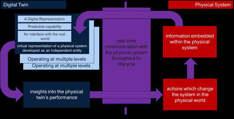
Digital twins have an important role to play in management of assets and their reliability and robustness, including:
• Monitoring the real-time operating state of the operating plant
• Providing predictive maintenance and fault diagnosis
• Enhanced safety due to reduced need to for building access
• Speed-up of manual maintenance operations based on visualisation and planning prior to physical intervention
• Assistance in training of staff
• Could facilitate mistake proofing through and rapid assessment of the physical environment (if linked to portable visualisation devised and augmented reality functionality)
• Could allow plant level cost impacts from sub-system or unit interventions to be understood (requires linking of sub-system level digital twins into a plant level representation)
• Could provide a backbone for progressive roll-out of monitoring and analytics implementations.
For example, analytic tools to support automated diagnostics, condition monitoring and health prediction of rotating plant through the application of both knowledge have been applied to pumps in power generating facilities based and data-driven AI techniques. These implementations, which fall short of full digital twin capability provide early fault diagnosis which enables increased equipment availability and reduced spares inventory.
PAgE 35 cAsE stuDy 9: EFFEcts OF DigitAl tWiNs OR MODEls ON REliAbility AND RObustNEss
53 Summarised from Grieves, M. and Vickers, J. (2017) ‘Digital twin: Mitigating unpredictable, undesirable emergent behaviour in complex systems’, in Transdisciplinary perspectives on complex systems. Springer, pp. 85–113
Realtime communication with the physical system through its life cycle
cAsE stuDy 10: EFFEcts OF DFx WHEN APPliED tO REliAbility AND RObustNEss
Design for X (DfX) whereby X is replaced by, in this case, reliability, is a method for designing a product with a particular focus in mind at that point in time. For reliability, this may influence the design by, for example, minimising the number of parts within the assembly, selecting materials graded to perform comfortably at the extremes of the operating conditions, opting for manufacturing processes which yield better properties within the material, and reducing material use where possible, such as shorter wiring lengths, to reduce the potential for failure and therefore increase the overall reliability. Df Reliability may also include accessibility to componentry to allow for ease of regular maintenance, repair or replacement of components.
These may result in trade-offs between competing design choices. For example, using reversible fixings such as fastenings rather than welds may allow for accessibility maintenance or repair, but it increases the number of component parts within the overall assembly. Ensuring the additional fixings are capable of performing their function within the expected working environment by selecting the appropriate type, material grade, fixing points etc., will be a critical aspect of the reliability and may require additional design changes (flanges to support holes for bolts, for example).
It is not a one-directional methodology and will likely show trade-offs not only within Df Reliability but across other DfXs as they are considered by the product designer. However, to increase the reliability and robustness, or even to demonstrate it, the practice should be encouraged.
sustAiNAblE liFEcyclE
As has been discussed throughout this document, sustainability of electrical machines will be crucial to the long-term reliance of them in an electrified future. The lifecycle of a product is typically considered cradle to grave (from design, material sourcing, manufacture, transportation, use up to the product end of life, in a linear fashion) or cradle to cradle (where end of life reroutes to design, thus creating a full cycle and moving into a circular economy system). To create a sustainable lifecycle is to consider each stage of said lifecycle and make changes to reduce the impact of that. This impact, in relation to net zero targets, is most often measured by the amount of CO2e emitted by a process.
Whilst electrical machines typically have lower in-use CO2e footprint than combustion engines, there is still a great need for manufacturing these products in a more environmentally friendly manner, taking into account the materials required, the sourcing and extraction of said materials and the potential options for rerouting them back into production at the end-of-life stage. Utilising frameworks such as the circular economy (discussed in detail in an earlier section) will be an important step in creating a more sustainable lifecycle for electrical machines, but the success of this is dependent on, for example, supplier sustainability uptake, infrastructure allowing for recovery strategies, economic viability and availability of alternative solutions. To aid in decisions across the value chain, documenting scope 1, 2 and 3 emissions should provide a benchmark on which to improve.
From the workshop, disassembly solutions was the most sought after topic with regards to product sustainability, in particular designing for disassembly and the reduction or elimination or resins from machines. Taking the latter, wet processes such as potting machines with resins and insulators does make them inherently more difficult to deal with at end of life than leaving them resin-free. This is because the resins cannot be easily removed from the component parts which in turn may not be removable from each other. Not only does this stifle efforts at end of life to remove and separate materials for recycling streams, but it also inhibits repair processes through the use phase. This may result in more work being carried out
PAgE 36
than was actually necessary, using more materials and costing more, or preventing repair going ahead and replacing the entire machine. Resins are beneficial for the performance of the machine, but this is impacting the other lifecycle stages and it is clear there is an appetite for their removal in aid of sustainability.
With regards design for disassembly, the same principles as were outlined in Case Study 10: Effects of DfX when applied to Reliability and Robustness stand. Some examples of design for disassembly may include incorporating reversible rather than irreversible fastenings (screws, bolts, interlocks rather than welds, interference fits, rivets etc.), using standardised fastener types rather than proprietary, elimination of coatings, platings and resins, the use of modular designs, material passports to help with separation and repair work, providing a manual for deconstruction, and designing layout which allows easy access to all components for the operator.
cOst
The push towards electrification is significant; with short term goals in place (such as the ban on petrol and diesel vehicles sales from 2030), there is limited time in which changes can be made to the manufacture of these machines to increase their sustainability. Changes made across the cradle to gate (design to ready to sell) stage must be considered not only from an environmental perspective, but an economic one also.
It was highlighted in section Rare Earth Elements (REE) that the fluctuation in price of materials such as neodymium had an economic impact on manufacturers. This uncertainty has led to research into reducing or eliminating the use of REEs in permanent magnets54. However, it was shown in Table 3 that whilst some REEs did have limited supply or the supply is considered threatened, other materials such as cobalt had similar availability concerns. Whilst the pricing of neodymium over a decade ago has spurred the search for REE-free magnets, it must not be forgotten that limited availability of other materials will likely see similar fluctuations. Both NdFeB and SmCo magnets are currently used in high-end electrical machines, and both are liable to price hikes. As such, the overall cost of the components should be considered with this in mind; to focus solely on a reduced window of elements (the REEs) may lead future production into potentially the same economic issues.
cAsE stuDy 11: EFFEcts OF AutOMAtiON ON cOst
Automation has played an increasingly important role in manufacturing operations for a number of decades now. Stereotypically factory automation is seen as the replacement of manual (human) work content with industrial robots or other mechanised devices, as seen in high volume manufacturing such as the automotive sector since the 1980s. The cost benefits of factory automation are however typically much more nuanced than this, especially in lower volume and higher complexity environments, with automation typically creating as many jobs as it replaces. For high value, high variety, small batch size manufacture, flexible automation provides a means of ensuring high levels manufacturing repeatability while avoiding the need for high investment in special to product tooling and fixed mechanisation. Well thought-through automated systems can be integrated with product definition and configuration processes to enable very high levels of manufacturing variety.
Through workshop activity with industrial partners the performance factors with the highest impact and the most applicability of early TRL research were assembled into Figure 9. This analysis was then used as the basis of the “‘so what? Assessment” for the performance factors.
54 https://www.researchgate.net/publication/362767707_The_possibility_of_using_permanent_magnets_without_rare_earth_elements_in_electric_motors
PAgE 37


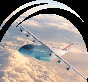


PAgE 38
Consolidated view of performance High viability of impact through low TRL Research Strong net zero impact identified Note or comment added by industrial partner Potential step change technology LEGEND Note of caution Thinner laminations Cryocooled resistive coils Switching frequency increase Frequency response Mechanical retention More compact design, optimise nonmagnetic (nonactive part)) Topology optimisation Power density, Torque Density 25kW/Kg by 2050 for aircraft (ATI) High Speed Reduced structural weight Reduced iron losses Higher magnetic loading Better Thermal management Reduced ohmic losses Processing thinner laminations Instrumented press tools Improved edge damage during cutting Monitoring machine parameters Burr removal (eg laser) Process and cut high silicon electrical steels Process and Cut amorphous alloys Processing of brittle materials Diffusing silicon after cutting Handling ultra thin (10 micron range) sheets) Stamping amorphous materials Include stamping effect Management of mechanical stress on finished core Joining of laminated stacks Higher temperature adhesive bonding Lower temperature operation Improve assembly Avoid breakage with thinner structures during assembly More precise placement Managing AC Loses Superconducting coils Reduced coil temperature In -process inspection Higher slot fill (getting as much conductor in the slot as possible and knowing where it is in advance) Geometry optimisation Modular design Definitions and standards Optimised winding Design Process improvements based on achievable slot fill Avoid twisting Thermal management / packing factor Reduced end winding length Optimisation of end windings Prediction of end winding during design More designed -in end winding arrangement Thinner strands, bend radius, techniques for managing transition and slack Generative design Prediction of end winding during design Improve rotor containment Rotor magnet loss Litz wire coils Rotor dynamics Cutting thin laminations without damage Reliability and performance of terminations Design to avoid critical response Reduced weight active components Reduced weight nonactive components Adoption of lightweight materials Composites Redesigned geometry Generative design Additive manufacture Combine non-active components in wider system Systems Engineering Thermal conductivity cross-slot High quality encapsulation in a high viscosity, highly loaded resin Pre-preg / wet winding High resistance hot spots in coil Process control Thermal mgmt. of end winding Direct liquid cooling Thermal mgmt. joints terminations Increase surface area to volume ratio eg splayed windings Thermal image analysis to help manage and identify good vs bad joints More accurate frequency dependant core loss model Machine architecture - The right number of slots and poles, how machine in manufactured (bonded vs welded etc) will have its own advantages – selecting correct for application Hollow conductor Potted end winding Reliable duty cycle More magnets Smaller air gap Magnetic material/ material composition Sustainability trade-offs Global optimisation of geometry Blairings failures, switching frequency, increase iron losses, higher temrature Local annealing eg laser Especially CoFe at 1100 degrees Celsius Avoid burr during cutting Cut multiple layers at price ->improve throughput to offset increased cutting Seal bearing Handling stranded windings Some will have a big impact on costs Pulse Width Modulation (PWM) effects on machine losses Material consideration (e.g. SMC for high frequency) Stress state, stress and damage due to winding Material choices Interior / surface segmentation Concentrated windings Older machines rewound with better insulation to improve efficiency of original machines Cryocooled system. These methods only make sense system facilitates it. (hydrogen cooling in hydrogen system) Supplier achieve factor) Prototyping vs “mass” production – can everything be added in real life manufacture? Design for sustainability Material utilisation during manufacture Net shape processes Precision casting Additive Design for material efficiency Cold forming / forging Buy - Near Scrap material reclamation during manufacture e.g electrical steel Mixed material magnets,
Throughlife analysis Degradation analysis Definitions needed: What is life? Lift expectancy? Cradle to grave etc cradle to cradle. Improve longevity of insulation system Preventive maintenance Design in replaceable bearings etc Prognostics to identify stress/available lifespan
for sustainability is key.
footprint using localised stock How does the entire chain work?
Figure 8 -
Improvements Future Manufacturing NET
Design
Minimise
Supplier capability in manufacturing – can they achieve what is set out? (i.e. increased fill factor)


How much improved efficiency can be made? Is the improvement worth the cost/manufacture efforts?


drivers and opportunities to address them
Reliability

PAgE 39 performance
Reversable connectors bolt vs weld Modularity not necessarily
Secondary life for battery Minimise production process Design for cost –grouping
materials, manufacture etc Productivity / competitiveness Choose right material More rigorous testing at
to proven reliability in condition Data analytics Embedded sensors Control of thermal interfaces in manufacture e.g heat sink to stator lamination stacks Material data bases Thermal modelling capability Design for accessibility geometry High Efficiency
just separate teeth, but just enough to take parts apart
the
start
Sustainable lifecycle Cost Seal and bearing losses Magnet losses Material choices surface segmentation Insulation control
kind of sense
(hydrogen system) System Losses Inverter Losses System level optimisation (machine,
Compactness Friction Oils AI/ Feedback loop to
time
and Robustness
These
if the
inverter, gearbox)
understand performance over
Particularly auxiliary motors i.e
Digital twins / Digital models Condition Monitoring Fault behaviour Design for reliability Ease of maintenance Reduced temperature / lifetime efficiency In-process monitoring and testing during manufacture Improve batch testing
many conditions, particularly in aerospace. How reliable would the simulations/digital
Design for Disassembly Elimination of resins Reduce use of resin DFMEA -> PFMEA Oversizing of machine How to prove the reliability of reman/refurb parts Minimise wiring between parts Minimise number of parts Multifunctional components Modular design Identification of failure modes Real time monitoring - CN machine “smart” “MTBF” - Skills availability - Training Fault Tolerance Fail Safe Complicates design, more parts Increased availability but doesn’t necessarily improve reliability Multiphase system System level consideration (invertor, bearings) Improved heat transfer inside slot Robust insulation system e.g. slot liner, resins etc Fault risk signature identification Through life digital twin Sometimes sensor won’t last life time of components - False results or need to replace. Standardisation Materials selection and resource efficiency Operational Design / machine type Legislative framework Automation Electrical supply chain development Legislation / tax incentives Minimise wastage Less rare earth material Strategic decision usage of resources – what is the understanding of recycled, reused, remanufactured parts Reuse does it mean tooling, material, parts? Reducing pool of needed tools etc, modularity of tooling parts etc Cross industry standards on COTS Slot pole System level considerati on (with control system) Air / om / water cooling system Size of machine (armature length / diameter) Disassembly Energy utilisation during manufacture Material reuse Secondary applications and approvals Repurposing - Legislation for standards connections Remanufacture Legislation to force improvements for remanufacturing Reuse opportunities at design stage Magnet recycling Durability, difficulty in joining aluminium Aluminium windings to aid recycling Eliminate or alternatives to adhesives Power management Power monitoring Working practices Micro grids Low energy processing Renewable energy input Laser vs stamping Heat losses - Energy recovery and reuse Robot manufacture Method of manufacture design Buy to fly ratio Near net shape methods magnets, use REE’s where needed. Standarisation to allow greater testing in lamination cutting Choice of material vs compliance to environmental requirements – uniformity in compliance globally - Manufacturing methods and extras-potting - Disassembly – how to repair remove components, separate materials at EoL
Difficulty with aging of product
Prioritisation of efficiency vs power/torque density etc Is application dependant Why do they need to be higher efficiency?
in aerospace, not propulsion
So
twin work
Improvements to Future Electrical Machine Manufacturing to enable NET ZERO
PAgE 40
Hig H impact, but non-viable W atc H D evelopment S in a DJ acent p R oblem S pace S Hig H impact, an D viable p R io R it Y t H eme S l o W impact, not ve RY viable avoi D l o W impact, but viable con S i D e R ba S e D on R e S ou R ce S an D F un D ing pR io R iti S ation o F imp R ovement S t H eme S • Power & torque density • High efficiency • Reliability & robustness • Cost mpacti on 2050 net oRze manceRoRFpe ovementRimp )Sgoal( viabilit Y o F making meaning F ul p R og R e SS via lo W t R l R e S ea R c H • Reduced resin use • Minimise wiring between parts • Oversizing of machine Better thermal management • Thermal management of joint termination • • Reduced weight non-active components • Reduced weight active components • Cryocooled resistive coils • Higher slot fill Reduced rare Earth metals • Embedded seneors • • Adoption of lightweight materials • Digital twins / digital models • Minimise number of parts • Design for disassembly • Design for reliability • Design for assembly • Repurposinglegislation standards • Automation • Productivity / competitiveness • Cross industry standards on COTS • Standardisation • Higher slot fill • Local annealing eg laser • Additive Manufacture • Super conducting coils • Cryocooled resistive coils • Optimised end winding • Optimised winding
Figure 9 - Prioritistation of improvement themes
PERFORMANcE
WITHIN THE FEMM HUB SCOPE, we have identified the following performance factors which will be used in the structuring of our roadmap. These address the areas that have been identified as addressing both machine and manufacturing performance:
• Power and torque density
• High efficiency operation
• High speed operation
• Reliability and robustness
• Sustainable lifecycle
• Cost
BEYOND THE FEMM Hub scope, it has become clear that machine supply cost is potentially a major barrier to progress in certain growth market sectors, and in driving the pace of electrification. It is recommended that this should be an area for potential innovation funding on a sectoral basis.
PAgE 41
FActORs –‘sO WHAt?’ AssEssMENt
POsitivE stEPs, DEsPitE uNcERtAiNty
Transitioning to net zero, through an increase in the production and use of electrical machines, will lead to market uncertainty and potential disruption to supply chains. This means that in addition to conventional research aimed at addressing specific gaps in product and process technology, there is a need to develop a vision for how the different threads of capability might come together in future products, factories and innovation ecosystems. In the following sections we have outlined a product, a future factory vision, and a set of technology monitoring focus areas which are needed to mitigate against the risks posed by an uncertain and developing industrial market.
FutuRE ElEctRicAl MAcHiNEs PRODuct visiON
Based on the analysis in the ‘technological drivers of change’ and the ‘performance factors and improvement’ sections, a future high value electrical machine product is expected to have the following features:
• E AsiER tO MANuFActuRE - more automations in manufacturing electrical machines.
• tigHtER tOlERANcEs - better tolerance control in manufacturing and assembly.
• FEWER NON-ActivE PARts - less weight in structural components which do not directly contribute to energy conversion.
• MORE iNtEgRAtED - more compact design and manufacture of electrical drive units, such as integrated electrical machine and inverter.
• MORE scAl AblE - more modular design and manufacture to enhance scalability.
• HigHER POWER DENsity - higher power/weight ratio or power/volume ratio by higher speed designs, higher torque density designs, or better cooling designs.
• HigHER EFFiciENcy - more efficient energy conversion by reducing losses in windings, cores and/or magnets.
• HigHER PROcEss cONtROl cAPAbility - a more accurate and efficient control of complex processes in manufacturing parts.
• bEttER sERvicE MONitORiNg - better in-service condition monitoring of key parts of electrical machines, such as temperatures and mechanical stress of windings and magnets.
• E AsiER tO DisAssEMblE FOR END OF liFE PROcEssiNg - a better design, manufacturing and assembly strategy to facilitate an effective disassembly for the end of life processing.
• MORE sustAiNAblE - use more sustainable materials, such as non-rare earth magnets, and use more sustainable manufacturing techniques, such as remanufacture/recycling for the end of life processing.
• lEss EMbEDDED ENERgy - higher energy efficiency in manufacturing and assembly of electrical machines.
• iMPROvED cOOliNg - More effective cooling techniques to facilitate a more efficient heat dissipation, such as direct cooling of windings and rotor.
PAgE 42
The future electrical machine manufacturing hub performs research in various grand challenges such as realising novel machine design freedoms from innovative manufacture, manufacture of features for in-service monitoring, light-weighting and multi-functional non-active components, from nominal core properties to in-service performance, manufacturing high performance coils and ultimate control, and sustainable manufacturing of electrical machine components for the circular economy. The correlations between the electrical machine manufacturing hub grand challenges and the features of a future high value electrical machine are illustrated in Figure 10. By way of example, manufacturing of light-weight and multi-functional structural components can contribute to tighter tolerances, fewer non-active pats, more integrated design, higher power density and better cooling capability.
Figure 10 mainly focuses on the physical capabilities of a future high value electrical machine while Figure 11 covers the potential digital capabilities such as condition monitoring of winding insulation health, condition monitoring of bearing currents, digital twin of machine performances, and digital twin of manufacturing and assembly operations.
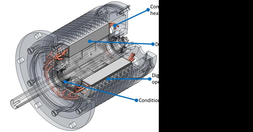
One technology which may bring a revolution into future electrical machines is the superconductors. The conventional low temperature (<30K) superconducting materials require liquid helium to maintain
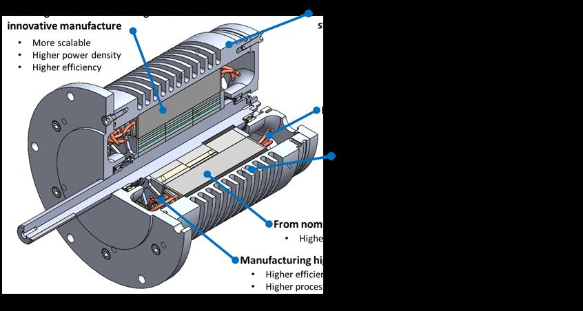
PAgE 43
Figure 10 - Physical capabilities of a future high value electrical machine
Figure 11 - Digital capabilities of a future high value electrical machine
their superconductivity, while the high temperature (>77K) superconducting materials only need liquid nitrogen to realise superconductivity. In the last decade, a set of ambient temperature superconducting materials were developed by using high-pressure superhydride, such as SH3, LaH10 and C-S-H with critical temperatures 203K, 260K and 288K, respectively. However, they require 155GPa, 190GPa and 267GPa to maintain their superconductivity. The price of either extreme low temperature or extreme high pressure hinders the wide application of superconductors in electrical machines. However, the future breakthrough in this superconductivity technologies, such as ambient temperature and ambient pressure superconductors, can result in a revolution in electrical machines, as superconductors can allow a massive current with very low losses and thus remarkably improve the power density while eliminate the soft magnetic material usage.
Figure 12 - The current development and future evolution of the superconducting materials (source: B. Lilia et al., "The 2021 room-temperature superconductivity roadmap," Journal of Physics: Condensed Matter, 2022).
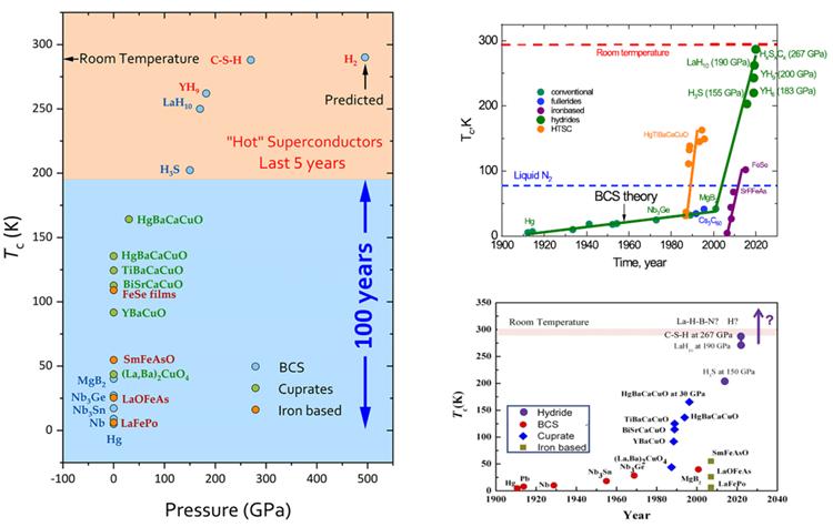
FutuRE ElEctRicAl MAcHiNEs FActORy visiON
Production systems for electrical machines typically occupy two extremes of scale: largely manual and flexible low volume production at one end, and highly automated yet inflexible mass production at the other. As demand electrical machines increase and manufacturers seek to transition between these two extremes, it would be beneficial to have automated manufacturing systems which can meet moderate production volumes but with a greater degree of flexibility in the volume and design. This would accommodate the significant uncertainty in the ultimate demand volumes and ongoing product development for emerging markets such as urban air mobility.
A further challenge in scaling up the manufacture of high-value electrical machines is that some of the technologies suited to lower-value or commodity machines are not suitable. For example, commercially available needle winding systems can achieve high-volume production but cannot yet produce complex distributed winding schemes with multiple strands or litz wire. Similarly, hairpin windings are well suited to automotive applications but might unacceptably restrict winding schemes and operating frequency.
PAgE 44
Additionally, whilst many of the processes available to manufacturers are common to several machine topologies, only some of these are inherently flexible allowing production to switch design according to immediate demands, and this is often at the expense of throughput compared to competing highvolume processes (e.g. laser cutting of laminations vs. stamping).
The FEMM Hub aims to develop novel manufacturing systems that afford some of the benefits of automation to low- and mediumvolume production of high-value electrical machines. Where processes cannot be automated for practical or economic reasons, digital tools developed through the Hub will support human operators to navigate the high levels of variability in products, and in capturing necessary data for certification.
A prerequisite for this vision of the flexible factory is a strong digital backbone connecting data from various physical manufacturing systems to operational infrastructure. Data captured, through infrastructure such as AMRC Factory+55 , firstly allows traceability and quality assurance in process (FEMM Hub XC2) but can also be interpreted by humans and intelligent systems to make decisions, e.g. scheduling preventive maintenance around work or switching tasks to accommodate upstream delays.
Specific process data can then be used to build models to estimate cycle time to aid costing and scheduling or to estimate the influence of manufacture based on part geometry (e.g. time taken to cut and heat imparted during laser cutting). Linking this to live data then yields a Digital Twin56 , affording visibility of the current state and in conjunction with other Twins, allowing the overall manufacturing system to be resilient to influences such as machine breakdowns, shortages etc.
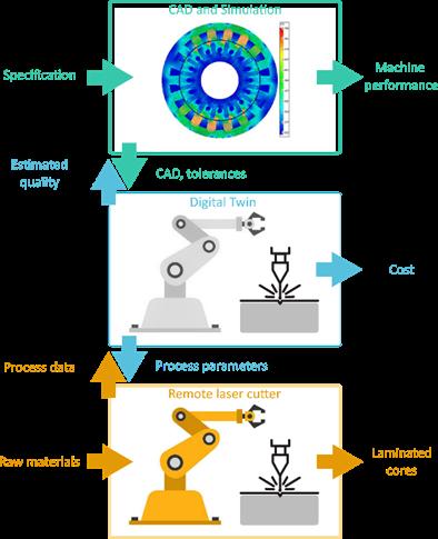
In summary, we envision that a future factory for high-value electrical machines will require the development of new flexible manufacturing processes to bridge the gap between low- and highvolume, and overall might exhibit the following qualities:
1. FlExiblE - accommodating a wide range of designs and volumes
2. EFFiciENt - making optimal use of raw materials and energy
3. cONNEctED - allowing data capture and exchange for traceability and quality assurance
4. REsiliENt - autonomously making decisions to avoid interruptions to production
5. sEMi-AutOMAtED - combining benefits of automation with skilled human operators.
tEcHNOlOgy
WAtcH, Pl ANNiNg AND MONitORiNg
There is an ongoing need to better understand and monitor the industrial needs for electrical machines across sectors. The work which has been summarised here represents a snapshot in time, and its relevance will erode if not maintained. Key issues such as the detailed analysis of material supply and
55 https://factoryplus.app.amrc.co.uk/
56 https://www.amrc.co.uk/pages/digital-twin-report
PAgE 45
demand have only been dealt with at a cursory level, partly due to lack of available public domain data, but it will be important to build on this work going forward by establishing:
• A live repository of aggregated product and material demand data, with an agreed process of industrial validation
• A dynamic roadmap, which can be updated based on progressive change to policy, supply and demand for commodities, industrial capability and market trends
• An aggregated technology watch activity, with the aim of providing current status summary information of technology and it develops in academia and through technology providers and OEM machine suppliers.
POsitivE stEPs DEsPitE uNcERtAiNty
WITHIN THE FEMM HUB SCOPE, we have developed thinking on both future product and future factory level. We have also undertaken the work described in this document as an attempt to map the future direction of electrical machines manufacture at a holistic level. This seems like a necessary view of the overall change that needs to be achieved, to go alongside the specific early TRL activity into specific areas of technology need that is the core business of the hub. Continuation of this system level approach will require an ongoing set of FEMM Hub activities to address the following needs:
• Further develop future electrical machine product concepts and system level vision. Where possible seek out opportunities to develop and test virtual and physical demonstrators
• Further develop future factory and supply chain concepts to provide a baseline capability bound, which future market requirements can be tested against. Seek out funding mechanisms for virtual and physical demonstration
• Maintain the FEMM Hub status as a global thought leader in the system level needs and challenges of future electrical machines manufacture, through maintenance, development and extension of the FEMM Hub roadmap.
BEYOND THE FEMM Hub scope, the need for large scale physical and virtual demonstrators of future machines will be essential especially to the UK’s ability to achieve and maintain technical leadership in this area. Funding bodies such as Innovate UK, ATI and APC should be encouraged to consider the best mechanism for funding such programmes and with timings that maximise their potential impact.
PAgE 46
–
‘sO WHAt?’
AssEMbliNg tHE ROADMAP
The analysis outlined in the previous sections is somewhat broad and ambitious in its intent to identify the drivers change and means of technical development in electrical machine manufacture to support net zero. It should be clear that the analysis on policy has identified four primary areas of need. The assessment of technology drivers has concluded in an acceptance of a high degree of market, product, and supply chain uncertainty and a set of four supply chain responses which will need to be met if in developing a viable manufacturing landscape. Given the FEMM Hub’s focus on early TRL engineering research, this analysis has attempted to map the underlying performance challenges and how to overcome them, resulting in identification of six performance factors. Figure 13 brings these key summary points together and articulated the future electrical machines net zero landscape that has emerged from the analysis.
The landscape is informative in articulating the key challenges that need to be addressed. It is also useful as a basis further analysis. The analysis of performance factor is a distinctive feature the approach taken. In assembling an output roadmap, it is useful to consider how position other related roadmap outputs against those performance factors. Roadmaps from ATI57 and APC58 have been considered in this way in Figure 17. This very simplistic analysis provides a level of validation of the FEMM Hub performance factors. Almost all of the identified roadmap requirements in both cases
PAgE 47
Complex and interrelated issues need to be addressed if eleCtriCal maChine manufaCturing Can support a net zero future performanCe faCtor 1: power and torque density performanCe faCtor 4: reliability and robustness performanCe faCtor 2: high effiCienCy performanCe faCtor 5: sustainable lifeCyCle performanCe faCtor 3: high speed operation performanCe faCtor 6: Cost need 2: Makingmachines better to perform better need 1: The provision of step change technologies for both machine performance and manufacturing resource efficiency need 3: Materials supply, potential replacement for scarce materials, and enablement of a circular economy approach need 4: Ability to support radical and uncertain growth supply Chain response 1: step Change in produCtion volume for high performanCe supply Chain response 4: substantial Cost reduCtion, to enable market disruption supply Chain response 2: flexibility in physiCal supply Chains and in the produCt development proCess supply Chain response 3:new CirCular eConomy provisions to support material availability under inCreased volume f uture p rodu C t f uture f a C tory r isk mitigations femm hub researCh
Figure 13 - Future Electrical Machines net zero landscape
57 ATI-Flyzero FZO-PPN-COM-0030 58 APC Electric Machines Roadmap 2020
• Reduced we assembly processes [2030]
• Pilot recycling plants[2030]
• Eliminated wet assembly processes [2040]
• Mass market e-machine recycling[2040]
• Highly decarbonised manufacturing and recycling[2040]
• ATI / Flyzero short –medium term need
• ATI / Flyzero long term need
• APC short-medium term need
• APC long term need
• High volume winding techniques with high fill factor[2030]
• Alternative low cost windings[2030]
• Advanced architecures (eg PM free, axial flux, transverse, flux, new rotor designs, high speed motors [2035]
• Reduced heavy rare earth content [2030]
• Enhanced e-steels[2030]
• Radical architectures (eg HTS, coreless motors) [2050]
• Advanced winding arrangement [2025]
• Copper Coated Aluminium Wire [2025]
• Nanofibre PEEK insulation [2025]
• Superconducting motor [2030]
• Dual air gap motor [2030]
• Ceramic Insulated Magnet Wire [2030]
• Carbon nanotube wire [2030]
• High volume winding techniques with high fill factor[2030]
bE tt E r tHE rmal manag
• Hard Magnetic material, higher temperature [2025]
• Hard Magnetic material: FeN [2030]
• Integrtated thermal managment[2035]
• Isolation materials for electrical strength and thermal conductivity [2035]
• Direct liquid cooling[2030]
• High performance windings eg graphene [2050]
• Advance cooling concepts[2040]
• Hard Magnetic material: FeN [2030] Hig HE r magn E tic loading
• Soft Magnetic Material [2025]
• High Speed permanent magnet motor [2025]
• Hard Magnetic material, higher temperature [2025]
rE duc
• Additive manufacture of passive components [2025]
• Composite manufacture of passive components [2025]
• Additive manufacture of magnetic materials [2030]
• 1st gen integrated drives (packaged closely) [2030]
• New machine designs via enhanced simulation techniques) [2030]
• Functionally integrated drive (housing, embedded electronics, high speed gearbox) [2050]
• ALM enabled machine designs[2050]
PAgE 48
Figure 14
Hig H Effici E ncy Pow E r d E nsity, t orqu E dE nsity Hig H sPEE d oPE ration c ost s ustainabl E lif E cycl E
- Overlay of headline aerospace and automotive electric machine roadmap expectations on identified performance factors.
E
E
m
nt
rE
E d o H mic
E s
duc
loss
E d
w E ig H t
structural
i m P rov E m E nts to f utur E El E ctrical m ac H in E m anufacturing to E nabl E n E t ZE ro
align well with both the high-level factors and the more detailed assessment outlined earlier in this document. It is interesting to note that there are differing expectations on required or expected timescales for the technologies for the two sectors. It is also worth noting that both of these sector based roadmaps lay out the expectations and requirements, rather than the means of delivery for the areas of development they identify.
Building on this stage of analysis it is also possible to align current and future FEMM project content on a similar map. This is shown in Figure 15. Through 2022 the FEMM Hub balloted industrial members on their priorities for technical content of the second phase of the hub. The supported ‘phase 2’ content shown in the figure are the outputs of that process. Further work, which will fall outside the scope of the hub is also shown, and would need to be the subject of future funding bids and / or partnerships with industry.
• Opportunities and development of remanufacturing options for electrical machines
• WP2.2: Manufacturing high performance coils and ultimate control
• WP1.2: Manufacturing of features for in-service monitoring
• Life cycle assessment of electrical machines and the opportunities
• WP2.3: Manufacturing technologies for flexibility and customisation
• Design for maintainability and end of life / re-use
• Elimination of resins
• Development of modular interfaces: Design of modular stator variations
• Integrate digital twin of remote laser process with motor design tools to close gap between asdesign and as-built
• WP1.1: Focus 1: Modular components: the effect of manufacturing on performance and tolerance
• WP1.1 Focus 2: Integrated design using new manufacturing methods and materials to enhance power density
• Advanced Phase Change Thermal Management of PEMD using bespoke components
• WP2.1: From nominal core properties to in-service performance
• In-process characterisation of additive / welding activities in EM
• Connections and Terminations: IR Thermography for automated inspection of enamel removal in Litz
• X-Cutting: X2: In-process tracking and traceability for zero-defect manufacture of electrical machines.
• WP1.3: Manufacturing of lightweight and multi-functional structural components form better
• Generic Phase Change Thermal Management of PEMD using standard components
• FEMM Hub phase 1 workstream
• FEMM Hub phase 2 workstream
• Future needs, gaps
• A manufacturers assessment of winding methods
• Torwards a through-life digital twin
• Collaborative robotic machine assembly cell development
• Explore alternatives to rare earths
• Cost based design for manufacture methodology
• Radical part count reduction –art of the possible, and cost-benefit approach
• A review of modular topologies
• Develop novel strategy for complete slot fill-factor needle winding
• Manufacturing process and high frequency characteristics of machines
• Coil manufacture with additive manufacture or incremental forming
• Design for manufacture of light-weighting of non-active components
• Remote laser post-cut treatment (e.g., partial cuts, hole arrays) to augment properties of electrical steels after cutting.
• High level system integrated design exemplar
• Superconducting machine manufacturing programme
• Processing of amorphous alloys
PAgE 49
Figure 15 - Overlay of legacy and forward looking FEMM Hub project content vs performance factors
Hig H Effici E ncy Pow E r d E nsity, t orqu E dE nsity Hig H sPEE d oPE ration rE liability and r obustn E ss c ost s ustainabl E lif E cycl E
i m P rov E m E nts to f utur E El E ctrical m ac H in E m anufacturing to E nabl E n E t ZE ro
In all cases Figure 16 articulates low TRL engineering research activity. Many of the areas which needs to be addressed in electrification for net zero fall outside of that definition. These outputs, can also be tabulated against the FEMM of areas of need to provide the rough timeline identified in Figure 17. This combines the NEEDS identified under NET ZERO and Policy response, with the identified Performance Factors, to establish a structure for the timeline. FEMM Hub activities to date, along with the industrially supported projects which make up the next phase of the programme are built into a high level timeline, along with action areas for the future or identified gaps in the current programme.
X-Cutting: X1: Sustainable manufacturing of electrical machine components for the circular economy
Design for maintainability and end of life / reuse
WP2.2: Manufacturing high performance coils and ultimate control
WP2.3: Manufacturing technologies for flexibility and customisation
WP1.2: Manufacturing of features for in-service monitoring
Opportunities and development of remanufacturing options for electrical machines
Life cycle assessment of electrical machines and the opportunities
Development of modular interfaces: Design of modular stator variations
Hierarchical Simulation and Optimisation of EM assembly
Collaborative robotic machine assembly cell development
In-process characterisation of additive / welding activities in EM
A manufacturers assessment of winding methods
Integrate digital twin of remote laser process with motor design tools to close gap between as-design and as-built
Connections and Terminations: IR
Thermography for automated inspection of enamel removal in Litz
Coil manufacture with additive manufacture or incremental forming
Focus 1: Modular components: the effect of manufacturing on performance and tolerance
WP2.1: From nominal core properties to in-service performance
X-Cutting: X2: In-process tracking and tractability for zero-defect manufacture of electrical machines.
Make better to perform better
WP1.1 Focus 2: Integrated design using new manufacturing methods and materials to enhance power density
A review of modular topologies
Elimination of resins
Radical part count reduction – art of the possible, and cost-benefit approach
Cost based design for manufacture methodology
Explore alternatives to rare earths
Torwards a through-life digital twin
Advanced Phase Change Thermal Management of PEMD using bespoke components
Generic Phase Change Thermal Management of PEMD using standard components
Manufacturing process and high frequency characteristics of machines
Develop novel strategy for complete slot fillfactor needle winding
Design for manufacture of light-weighting of non-active components
Remote laser post-cut treatment (e.g., partial cuts, hole arrays) to augment properties of electrical steels after cutting.
Superconducting machine manufacturing programme
High level system integrated design exemplar
Processing of amorphous alloys
Design and make study of a lightweight sustainable electrical machine for aerospace
Maintenance and further development of the FEMM hub roadmap
Factory / supply chain level demo
Demo programmes aero, renewables, etc
Quantitative materials availability and demand assessment
PAgE 50
Power density, Torque Density High Speed Operation High Efficiency Reliability and Robustness Cost Sustainable lifecycle Materials and re- use Radical and uncertain growth Risk mitigations Future factory Future machine Technology watch and planning Future needs, gaps FEMM Hub Phase 2 FEMM Hub Phase 1 Materials and re- use Radical and uncertain growth Materials and re- use Radical and uncertain growth Materials and re- use Radical and uncertain growth Materials and re- use Radical and uncertain growth Step change technology Materials and re- use Radical and uncertain growth Step change technology Step change technology Step change technology Step change technology Step change technology Make better to perform better Make better to perform better Make better to perform better Make better to perform better WP1.3: Manufacturing of light-weight and multifunctional structural components form better Make better to perform better WP1.1:
Figure 16 - FEMM Hub Activity Roadmap
As a final step in assembling the current phase of roadmap development into an intelligible roadmap output, the contents of Figure 17 have been put together with the net zero landscape contents as outlined in Figure 16. The outcome is seen in Figure 17, which combines technical areas of research with planning principles and high level challenges on the road to net zero.
Substantial cost reduction, to enable market disruption
New circular economy provisions to support material availability under increased volume
Flexibility in physical supply chains and in the product development process
Step change in production volume for high performance
Future Factory Technology Planning
Future Products
Advanced Phase Change Thermal Management of PEMD using bespoke components Generic Phase Change Thermal Management of PEMD using standard components Develop novel strategy for complete slot fillfactor needle winding Integrate digital twin of remote laser process with motor design tools to close gap between asdesign and asbuilt
cycle assessment of electrical machines and the opportunities Coil manufacture with additive manufacture or incremental forming Design and make study of a lightweight sustainable electrical machine for aerospace Hierarchical Simulation and Optimisation of EM assembly Development of modular interfaces: Design of modular stator variations Inprocess characterisation of additive / welding activities in EM Collaborative robotic machine assembly cell development A manufacturers assessment of winding methods
NEED 4: Ability to support radical and uncertain growth
NEED 3: Materials supply, potential replacement for scarce materials, and enablement of a circular economy approach
NEED 2: Making machines better to perform better
NEED 1: The provision of step change technologies for both machine performance and manufacturing resource efficiency
PAgE 51
17
Power density, Torque Density High Speed Operation High Efficiency Reliability and Robustness Cost Sustainable lifecycle Risk mitigations 2027+ 20232026 20192023 WP1.3: Manufacturing of lightweight and multifunctional structural components form better WP1.1: Focus 1: Modular components: the effect of manufacturing on performance and tolerance WP1.1 Focus 2: Integrated design using new manufacturing methods and materials to enhance power density WP1.2: Manufacturing of features for inservice monitoring WP2.1: From nominal core properties to inservice performance WP2.2: Manufacturing high performance coils and ultimate control WP2.3: Manufacturing technologies for flexibility and customisation XCutting: X1: Sustainable manufacturing of electrical machine components for the circular economy XCutting: X2: Inprocess tracking and tractability for zerodefect manufacture of electrical machines. Design for manufacture of lightweighting of nonactive components Opportunities and development of remanufacturing options for electrical machines Maintenance and further development of the FEMM hub roadmap A review of modular topologies Manufacturing process and high frequency characteristics of machines Life
Figure
- FEMM Hub high level roadmap
Connections
Remote
Factory
Quantitative
Cost
–
Design
life / reuse Elimination
and Terminations: IR Thermography for automated inspection of enamel removal in Litz
laser postcut treatment (e.g., partial cuts, hole arrays) to augment properties of electrical steels after cutting.
supply chain level demo Demo programmes aero, renewables, etc Superconducting machine manufacturing programme
materials availability and demand assessment High level system integrated design exemplar Processing of amorphous alloys
based design for manufacture methodology Explore alternatives to rare earths Torwards a throughlife digital twin Radical part count reduction
art of the possible, and costbenefit approach
for maintainability and end of
of resins
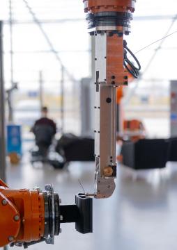
liMitAtiONs AND FutuRE WORk
This work has attempted to articulate what net zero could mean in terms of the manufacturing challenges for future electrical machines. It has done this based primarily on UK industrial input and public domain sources and the expertise of both the FEMM Hub research community and our industrial partners. Necessarily this has been a limited activity based on finite available time. The following points identify current limitations, and point to the need for more work to further develop the necessary understanding to support comprehensive research planning:
1. This has been primarily a UK based analysis, and while some international sources have been used the main industrial input both in terms of industrial expertise, and analysis of sector level projects has effectively taken the UK as a case in point. Future work on roadmap development will need to include a thorough assessment of international work content and industry projections.
2. The FEMM Hub focus is low TRL research, and the selected roadmap content has been chosen on this basis. Time has not permitted a proper analysis of ‘out of scope’ for FEMM Hub activity (i.e. high TRL and industrial deployment). This is a significant omission, as without it there is no basis for confidence that all potential research gaps have been found.
3. At the onset of the roadmap development work it was hoped that a quantification of 2050 materials demand versus global supply for scarce resources would be possible. This quantification is problematic because of large uncertainties in future product architectures, markets and the modes of use of future technology, however future work on technology planning for electrical machines should explore the possibilities for supply and demand analysis for critical materials. The growing theme of work on circular economy would benefit from better data on the scale of the problem and even quantification of the uncertainty bound.
Likewise, in plotting the path to net zero it would be desirable to indicate the extent to which research outcomes from the FEMM Hub work alongside more general improvement activities to close the gaps in performance factors e.g. power density by ATI and APC. This analysis is best done by means of a specific case studies and opportunities to perform this analysis will be sought out as a hub and its partners seek to establish future product and factory level demonstrators.
4. While it would be nice to think that Figure 15 represents a comprehensive set of electrical machine research needs required to achieve net zero, this is some way from being the case. The landscape elements (needs, supply chain responses and performance factors) are considered credible and articulated at a high level. The net zero challenge for machines has highlighted that many more research questions and challenges can and should be posed. In the next phase of roadmap development, the intention will be to move on from the priority areas selected by Hub partners, to a more complete list.
5. Future product and future factory concept definition is an integral part of the vision for future electrical machines, and the work described here is a good start. However, these sections are currently somewhat disconnected from the main thrust of this document, and the next interation of the roadmap needs to define the integration of low TRL research, factory adoption and the pathway to future machines more explicitly.
PAgE 53
Better Thermal management
APPENDix
POWER DENSITY, TORQUE DENSITY 25KW/KG BY 2050 FOR AIRCRAFT (ATI)
Some will have a big impact on costs
Global optimisation of geometry
• More compact design, optimise non-magnetic (non-active part)
Pilures, switching frequency, increase iron losses, higher temrature
Switching frequency increase
Frequency response
• Mechanical retention
Sustainability trade-offs
Reduced iron losses
⭐
Reliable duty cycle
Potted end winding
Thermal mgmt. of end winding
• Direct liquid cooling
Thermal mgmt. joints terminations
Thermal image analysis to help manage and identify good vs bad joints
• Increase surface area to volume ratio eg splayed windings
High resistance hot spots in coil
• Process control
Thermal conductivity cross-slot
• High quality encapsulation in a high viscosity, highly loaded resin
• Pre-preg / wet winding
More accurate frequency dependant core loss model
Potted end winding
• Processing of brittle materials
• Stamping amorphous materials
• Diffusing silicon after cutting
• Handling ultra thin (10 micron range) sheets)
Process and cut high silicon electrical steels
Improved edge damage during cutting
⭐Local annealing eg laser
Especially CoFe at 1100 degrees Celsius
Burr removal (eg laser)
Avoid burr during cutting
• Monitoring machine parameters
Processing thinner laminations
• Instrumented press tools
Cut multiple layers at price ->improve throughput to offset increased cutting
Include stamping effect
Improve assembly
• Avoid breakage with thinner structures during assembly
Management of mechanical stress on finished core
Machine architecture
The right number of slots and poles, how machine in manufactured (bonded vs welded etc) will have its own advantages –selecting correct for application
Material consideration (e.g. SMC for high frequency)
Joining of laminated stacks
In-process inspection
Higher temperature adhesive bonding
Reduced ohmic losses
Design Process improvements based on achievable slot fill
Managing AC Loses
Superconducting coils
Hollow conductor
⭐ Cryocooled resistive coils
Reduced coil temperature
• Lower temperature operation
Material choices
Older machines rewound with better insulation to improve efficiency of original machines
Insulation control
Cryocooled system. These kind of methods only make sense if the system facilitates it. (hydrogen cooling in hydrogen system)
⭐ Higher slot fill (getting as much conductor in the slot as possible and knowing where it is in advance)
• Definitions and standards
Concentrated windings
• Optimised winding
• Modular design
Stress state, stress and damage due to winding
• More precise placement
• Avoid twisting
• Thermal management / packing factor
Reduced end winding length
• Optimisation of end windings
– Thinner strands, bend radius, techniques for managing transition and slack
• Prediction of end winding during design
• More designed- in end winding arrangement
– Geometry optimisation
Appendix Figure a - Power and Torque performance factors
Higher magnetic loading
Magnetic material/ material composition
More magnets
Smaller air gap
Reduced structural weight
Reduced weight active components
Systems Engineering
Reduced weight nonactive components
• Adoption of lightweight materials
• Lightweight metals
• Composites
Combine non-active components in wider system
• Topology optimisation
• Additive manufacture
• Generative design
PAgE 54
Key Note or comment added by industrial partner ⭐ Strong net zero impact identified High viability of impact through low TRL Research
Potential step change technology
Magnet losses
���� Material choices
���� Interior / surface
���� Segmentation
���� Geometry
Ǜ Prioritisation of efficiency vs power/ torque density etc Is application dependant
Ǜ Why do they need to be higher efficiency? Particularly auxiliary motors i.e in aerospace, not propulsion
Ǜ How much improved efficiency can be made? Is the improvement worth the cost/ manufacture efforts?
Ǜ Supplier capability in manufacturing – can they achieve what is set out? (i.e. increased fill factor)
Reduced ohmic losses
Reduced end winding length
Design Process improvements based on achievable slot fill
Managing AC Loses
���� Handling stranded windings
Superconducting coils
���� Hollow conductor
Cryocooled resistive coils
Reduced coil temperature
Machine architecture
The right number of slots and poles, how machine in manufactured (bonded vs welded etc) will have its own advantages –selecting correct for application
���� Higher slot fill (getting as much conductor in the slot as possible and knowing where it is in advance)
• In-process inspection
• Geometry optimisation
• Modular design
���� Concentrated windings
• Definitions and standards
• Optimisation of end windings
• Thermal management / packing factor
Stress state, stress and damage due to winding
• More precise placement
���� Cryocooled system. These kind of methods only make sense if the system facilitates it. (hydrogen cooling in hydrogen system)
• Avoid twisting
���� Older machines rewound with better insulation to improve efficiency of original machines
���� Insulation control
Reduced iron losses
Joining of laminated stacks
• Higher temperature adhesive bonding
• Lower temperature operation
Process and Cut amorphous alloys
• Handling ultra thin (10 micron range) sheets)
• Diffusing silicon after cutting
• Processing of brittle materials
• Stamping amorphous materials
Improved edge damage during cutting
Local annealing eg laser
���� Especially CoFe at 1100 degrees Celsius
Burr removal (eg laser)
���� Avoid burr during cutting
• Monitoring machine parameters
Process and cut high silicon electrical steels
Processing thinner laminations
Instrumented press tools
���� Include stamping effect
���� Cut multiple layers at price ->improve throughput to offset increased cutting
Improve assembly
• Avoid breakage with thinner structures during assembly
Management of mechanical stress on finished core
���� Machine architecture
The right number of slots and poles, how machine in manufactured (bonded vs welded etc) will have its own advantages
– selecting correct for application
���� More accurate frequency dependant core loss model
���� Material consideration (e.g. SMC for fhigh requency)
Seal and bearing losses
Pulse Width Modulation (PWM) effects on machine losses
System Losses
Oils
System level optimisation (machine, inverter, gearbox)
Compactness
AI/ Feedback loop to understand performance over time
Friction
Inverter Losses
Appendix Figure b - High Efficiency performance factors
PAgE 55
Key Ǜ Note of caution ���� Note or comment added by industrial partner Strong net zero impact identified High viability of impact through low TRL Research Potential step change technology
HIGH EFFICIENCY
Reduced temperature / lifetime efficiency
���� Material data bases
���� Improved heat transfer inside slot
���� Robust insulation system e.g. slot liner, resins etc
���� Control of thermal interfaces in manufacture
���� Thermal modelling capability
RELIABILITY AND ROBUSTNESS
Ǜ Difficulty with aging of product
Condition Monitoring
Fault risk signature identification
Sometimes sensor won’t last life time of components - False results or need to replace
More rigorous testing at start to proven reliability in condition
• Prioritisation of efficiency vs power/torque density etc Is application dependant
⭐ Embedded sensors
• Through life digital twin
Data analytics
Design for reliability ����⭐
⭐ Minimise number of parts
⭐ Minimise wiring between parts
���� DFMEA -> PFMEA
⭐ Oversizing of machine
���� Multifunctional components
Fault behaviour
Fault Tolerance
System level consideration (invertor, bearings)
Fail safe
Ǜ Complicates design, more parts Increased availability but doesn’t necessarily improve reliability
⭐ Multiphase system
Ease of maintenance
Modular design
���� Skills availability Training
���� Real time monitoring
CN machine “smart” “MTBF”
Identification of failure modes
���� Multiphase system
Key
Ǜ Note of caution
���� Note or comment added by industrial partner
⭐ Strong net zero impact identified
���� High viability of impact through low TRL Research
���� Potential step change technology
���� How to prove the reliability of reman/ refurb parts
Digital twins / Digital models
���� In-process monitoring and testing during manufacture
• Improve batch testing
Ǜ How reliable would the simulations/ digital twin work
Disassembly
���� Elimination of resins
⭐ Minimise wiring between parts
⭐ ���� Design for Disassembly
���� Eliminate or alternatives to adhesives
���� Durability, difficulty in joining aluminium
Modularity not necessarily just separate teeth, but just enough to take parts apart
Reversable connectors bolt vs weld
Aluminium windings to aid recycling
Appendix Figure c- Reliability and Robustness performance factors
PAgE 56
����⭐
Material utilisation during manufacture
Mixed material magnets, use REE’s where needed.
Design for material efficiency
���� Scrap material reclamation during manufacture e.g electrical steel
Net shape processes
• Additive
• Precision casting
• Cold forming / forging
���� Buy to fly ratio - Near net shape methods
Method of manufacture design
���� Choice of material vs compliance to environmental requirements – uniformity in compliance globally
• Manufacturing methods and extras-potting
• Disassembly – how to repair remove components, separate materials at EoL
���� Standarisation to allow greater testing in lamination cutting
Key
Ǜ Note of caution
���� Note or comment added by industrial partner
⭐ Strong net zero impact identified
���� High viability of impact through low TRL Research
���� Potential step change technology
SUSTAINABLE LIFECYCLE
Design for sustainability
Design for sustainability is key. Minimise footprint using localised stock How does the entire chain work?
• Design in replaceable bearings etc
Improve longevity of insulation system
Preventive maintenance
Degradation analysis
Through-life analysis
Method of manufacture design
Ǜ Definitions needed: What is life? Lift expectancy? Cradle to grave etc cradle to cradle.
Disassembly
Modularity not necessarily just separate teeth, but just enough to take parts apart
Secondary life for battery
Remanufacture
Aluminium windings to aid recycling
Reversable connectors bolt vs weld
���� Elimination of resins
⭐ Reduce use of resin
⭐ ���� Design for Disassembly
���� Eliminate or alternatives to adhesives
���� Durability, difficulty in joining aluminium
Material re-use
Secondary applications and approvals
���� Reuse opportunities at design stage
���� Repurposing - Legislation for standards connections
���� Legislation to force improvements for remanufacturing
���� Magnet recycling
���� Reducing pool of needed tools etc, modularity of tooling parts etc
Energy utilisation during manufacture
Low energy processing
Power management
Micro grid
Working practices
���� Laser vs stamping
���� Renewable energy input
���� Heat losses - Energy recovery and reuse
Power monitoring
Materials selection and resource efficiency
⭐ Less rare earth material
Choose right material
Appendix Figure d- Sustainable lifecycle performance factors
PAgE 57
Standardisation
���� Reducing pool of needed tools etc, modularity of tooling parts etc
���� Aerospace – what is the understanding of recycled, reused, remanufactured parts
���� Strategic decision – usage of resources
���� Reuse does it mean tooling, material, parts?
���� Cross industry standards on COTS
Design / machine type
���� Size of machine (armature length / diameter)
���� Slot pole combination
���� System level consideration (with control system)
���� Design for cost – grouping the materials, manufacture etc
���� Air / om / water cooling system
Materials selection and resource efficiency
⭐ Less rare earth material
���� Minimise production process
Minimise wastage
Choose right material
Operational
���� Productivity / competitiveness
���� Electrical supply chain development
���� Automation
Legislative framework
Legislation / tax incentives
Appendix Figure e - Cost performance factors
Material re-use
Secondary life for battery
���� Magnet recycling
Secondary applications and approvals
Remanufacture
���� Reuse opportunities at design stage
���� Repurposing - Legislation for standards connections
���� Legislation to force improvements for remanufacturing
PAgE 58
Key Ǜ Note of caution ���� Note or comment added by industrial partner ⭐ Strong net zero impact identified ���� High viability of impact through low TRL Research ���� Potential step change technology
COST
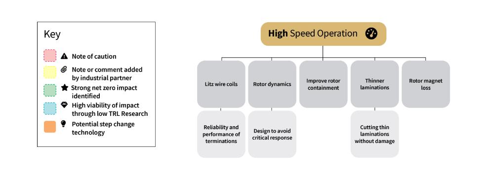
PAgE 59
Figure 8f - High speed operation
https://www.facebook.com/FEMMhub/


https://www.linkedin.com/company/epsrc-future-electricalmachines-manufacturing-hub


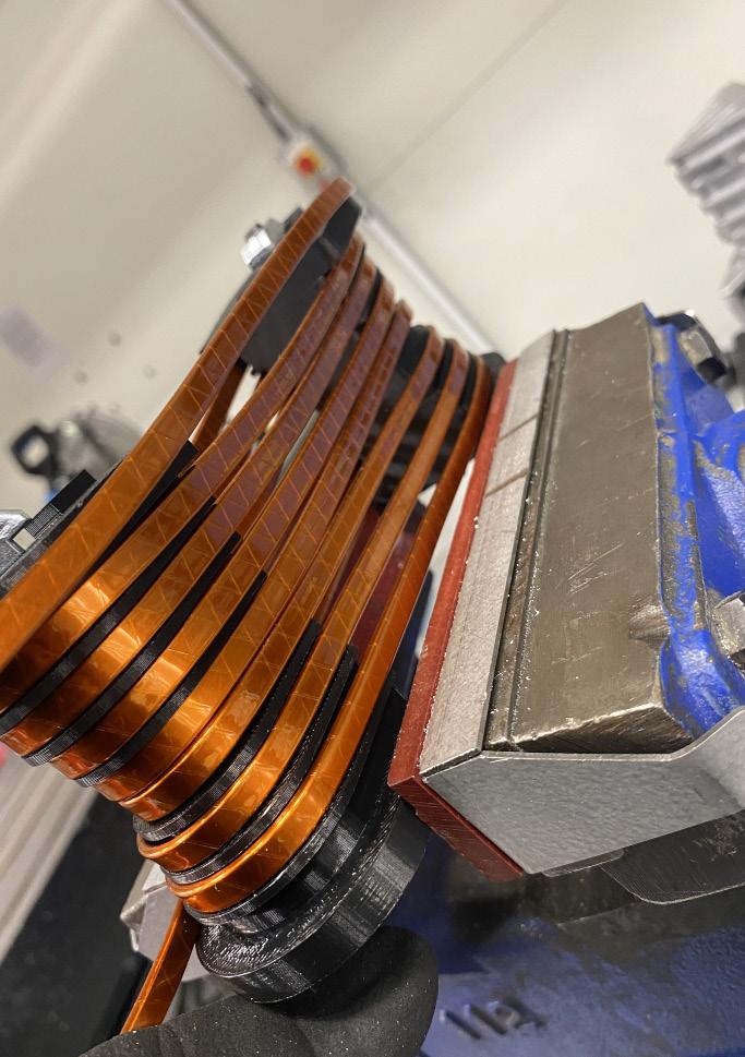
@FEMMhub
0114 222 5875

of
Department
Electronic and Electrical Engineering, Sir Frederick Mappin Building, University of Sheffield, Mappin Street, Sheffield, S1 3JD.
