gc 1.1 re Alising noVel mAcHine design Freedoms From innoVAtiVe mAnuFActure
gc 1.2 mAnuFActuring oF Fe Atures For in-serVice monitoring
gc 1.3 mAnuFActuring oF ligHt-WeigH And multi-FunctionAl structurAl components
gc 2.1 From nominAl core properties to in-serVice perFormAnce gc 2.2 mAnuFActuring HigH perFormAnce coils And ultimAte control
2.3
2.4
Femm pHds 1st Fe Asibility cAll
Welcome
The second year of the Hub activities have taken place entirely under various levels of operating restrictions in the host institutions and this has inevitably impacted on the rate of progress on the elements of the research programme which are reliant on access to laboratories and workshops for experimental work or equipment design and build. This has necessarily required some flexibility as plans have been modified to focus on modelling and simulation studies with an expectation of a period of focus on experimental activities over the coming year to bring the balance back on track. Despite recent challenges, with considerable ingenuity and institutional commitment to partly re-open facilities, we have managed to make some steps forward in recent months with some notable achievements in the commissioning of facilities and the initiation of experimental studies as will be apparent in the various individual Grand Challenge project updates later in this Annual Report.
Femm Hub director proFessor gerAint je Well
our industry partners. In the past year, of the 83 individual Grand Challenge monthly meetings, we have had industry partners attending and providing valued input in over 53% of the meetings.
It is heartening to see a steady stream of conference and journal papers emerging from the Hub activities and our researchers and academic staff receiving an increasing number of invitations to speak at prestigious conferences and industry workshops. Over the past year, the core research programme has been supplemented through the award of four feasibility studies to researchers from other UK Universities, further details of which are in page 42-45 of this report. We will be launching our next round of feasibility studies in the Autumn in collaboration with a number of other EPSRC Manufacturing Hubs.
We have made real progress in the past year in drawing our industry partners into detailed aspects of the research activities. Following discussions with our Industry Advisory Board on means of enhancing engagement with engineers within their companies, we opened up our monthly technical project meetings to all
We have expanded our training activities for the Hub team in the past year. Having previously run a general introduction to electrical machines course in the first year on a face-toface basis, in the past year we have run more focussed and in-depth technical on-line courses. These have proved popular with both the Hub researchers and engineers from our industry partners with average on-line attendance of over 90 for the courses run this year. We will continue to expand this activity over the coming year, with several course already scheduled in the coming months (see the Hub website for further details of upcoming courses) and see this as a valued activity in terms of both enhancing the skills of our research team and engineers within our industry partners and in initiating valuable discussion on new avenues of research. We are also working on the development of the research team in terms of broader skills and following consultation with the researchers have set up a 3 day TRIZ training course in July 2021.
The Hub continues to play a role in shaping the wider landscape in electrical machine manufacture in the UK, with individuals having been actively involved in two EPSRC Strategic Advisory Teams (Manufacturing and Engineering), The UK Manufacturing Forum, ATI Electrification Centre Workshops, Driving the Electrical Revolution Advisory Group, NAFEMS Optimisation Working Group, the RAEng Regional Engagement Award and the EPSRC Connected Everything Network Plus.
We go into the third year of the Hub activities with a real sense of momentum and expectations that our experimental research activities will soon get back to full-steam.
tHe Future electricAl mAcHines mAnuFActuring Hub: putting uk mAnuFActuring At tHe ForeFront oF tHe electriFicAtion re Volution
tHe Hub Will Address key mAnuFActuring cHAllenges in tHe production oF HigH integrity And HigH VAlue electricAl mAcHines in tHe FolloWing sectors: AerospAce, energy, HigH VAlue AutomotiVe, premier consumer
objectiVes
To establish electrical machine manufacturing as a recognised research discipline in the UK with a critical mass of activity which is internationally leading.
To create an open and inclusive academic, innovation and industry communities around the Hub that provides supported access to the research outputs we develop and stimulates new collaborations. 1 2 3 4 5 6 7 8
To develop innovative manufacturing processes and technologies to improve the integrity and in-service reliability of high performance electrical machines.
To bring rigorous leading-edge manufacturing systems and digital manufacturing research into high value electrical machine manufacture with ultimate control and flexibility.
To embody the research findings in an array of hardware demonstrators and modelling tools to support Technology Readiness Level (TRL) scale up and wider industry/academic engagement.
To rapidly transition emerging technology through to industrial application by pulling proof of principle/concept manufacturing systems through to manufacturing research demonstrators prototypes for industry to work on alongside Hub researchers and develop for application.
To improve the UK skills base, including within partner companies, in the field of electrical machines and their manufacture.
To support UK manufacturing industry as electrical machines increasingly become core products in new sectors.
Hub pArtners
mr ben morgAn AMRC
Hub mAnAger dr lAurA o'keeFe The University of Sheffield
deputy director
proFessor AsH tiWAri The University of Sheffield
proFessor micHAel WArd ARFC, University of Strahcyle
executiVeteAm. inVestigAtors.
proFessor rAb scott AMRC
proFessor robin pursHouse
Sheffield University
proFessor jiAbin WAng Sheffield University
proFessor Al AsdAir mcdonAld
Edinburgh University
Hub director
proFessor gerAint je Well The University of Sheffield
dr glynn Atkinson
Newcastle University
proFessor bArrie mecroW Newcastle University
proFessor zi-QiAng zHu Sheffield University
reseArcHers.
nAbeel AHmed Newcastle University
AbbAs kAzemi Amiri University of Strathclyde
xiAo cHen The University of Sheffield
ryAn diVer AMRC
micHAel FArnsWortH The University of Sheffield
giAnmArco pisAnelli AMRC
lloyd tinkler AMRC
diVyA tiWAri Research Associate The University of Sheffield
ste Ve Forrest The University of Sheffield
dAVid He Witt The University of Sheffield
jill miscAndlon AFRC
rAFAl Wrobel Newcastle University
Alexei Winter AMRC
diVyA tiWAri The University of Sheffield
gl Adys bengHAliA
scientiFic
AdVisory
boArd brings together leading academics from across electrical machine and manufacturing research.
They advise on and help support the development and growth of the hub, including its leadership role within the national research and innovaton landscape.
AdVisory boArd brings together senior figures from the
They appraise and advise on the impact activities to maximise the opportunities for knowledge exchange and ensure the Hub delivers impact for UK industry.
rese ArcH progrAmme.
The research activities encompassed by the Hub contain a combination of a-priori defined research projects delivered through two Grand Challenge (GC) themes and accompanying Hub PhD studentships, and an array of more flexible activities where the specifics of the research will emerge throughout the lifetime of the Hub.
grAnd cHAllenge tHemes
1. Realising novel machine designs from innovative manufacture
2. Manufacturing of features for in-service performance
Hub PhD studentships
EPSRC projects
Fe Asibility projects
3. Manufacture of light-weight and multifunctional components process innoVAtion, monitoring And simul Ation
1. Form nominal core properties to in-service performance.
2. Manufacturing high performance coils with ultimate control.
3. Manufacturing technologies for flexibility and customisation.
4. In-process tracking & tracability for zero defect manufacture.
5. Sustainable manufacturing of electrical machine components for the circular economy.
AtForm rese ArcH
- Manufacturing of lightweight structural components for high performance electrical machines by electromagnetic pulse technology (EMPT)
- HiPPES – High Performing and Processible Electrical Steels
- Industrial Manufacture of Marinised Coils – IMMCoil
- Additive Manufacturing for Next Generation Functional Integration of Windings and Thermal Management in Future Electrical Machines
Industry funded PhD studentship
Direct industry funded projects
HVM Catapult projects
UK Gov. / Industry funded projects (ATI, APC, IUK)
- Proof of concept - Secondments
gc 1.1. re Alising noVel mAcHine designs From innoVAtiVe mAnuFActure.
Work-package lead: Dr Glynn Atkinson (Newcastle)
- Rafal Wrobel, Nabeel Ahmed (Newcastle)
gc 1.2. mAnuFActuring oF Fe Atures For in-serVice perFormAnce.
Work-package lead: Professor Jiabin Wang (Sheffield)
- David Hewitt, Hao Chen (Sheffield)
gc 1.3. mAnuFActure oF ligHt-WeigHt And multi-FunctionAl components.
Work-package lead: Dr Jill Miscandlon (AFRC)
- Mehrad Amiri, Charlie Scott (AFRC/Strathclyde)
- Alasdair McDonald (Edinburgh)
- Geraint Jewell, Steve Forrest, Xiao Chen, Reece Elbet, Dan Harper (EEE, Sheffield)
gc 2.1. Form nominAl core properties to in-serVice perFormAnce.
Work-package lead: Professor Geraint Jewell (EEE, Sheffield)
- Xiao Chen, Reece Elbet (EEE, Sheffield)
gc 2.2. mAnuFActuring HigH perFormAnce coils WitH ultimAte control.
Work-package lead: Dr Steve Forrest (EEE, Sheffield)
gc 2.3. mAnuFActuring tecHnologies For Flexibility And customisAtion.
Work-package lead: Dr Lloyd Tinkler (AMRC)
- Alexei Winter, Gianmarco Pisanelli (AMRC)
- Geraint Jewell (EEE, Sheffield)
gc 2.4. in-process trAcking & trAcAbility For zero deFect mAnuFActure.
Work-package lead: Professor Ash Tiwari (ACSE, Sheffield)
- Divya Tiwari, Michael Farnsworth, Ze Zhang (ACSE, Sheffield)
gc 2.5. sustAinAble mAnuFActuring oF electricAl mAcHine components For tHe circul Ar economy.
Work-package lead: Dr Jill Miscandlon (AFRC)
- Ash Tiwari, Divya Tiwari (ACSE, Sheffield)
- Lloyd Tinkler (AMRC)
- Glynn Atkinson (Newcastle)
- Gladys Benghalia, Leigh Paterson (AFRC)
gc 1.1: re Alising
noVel mAcHine design Freedoms From innoVAtiVe
mAnuFAc ture
This work-package focusses on harnessing emerging and innovative manufacturing methods to enable alternative machine topologies and demonstrate how performance, efficiency and material utilisation can all be improved. A core of this work is on using modularity to gain higher torque density and thermal capability. This modular approach does however introduce a series of issues, which this workpackage will investigate.
modul Arity in electricAl mAcHines WorksHop december 2020
Over 30 attendees joined in a workshop exploring modularity in electrical machines. This session helped to gather insight into the manufacturing challenges posed by modular machines, their potential solutions and areas where modularity ought to target. Interesting direction and questions emerged over the session which will help to direct this work package during 2021 and 2022:
• What is the reason for modularity – this work package will aim to determine this quantitatively and highlight the machine sizes and applications where modularity can benefit.
• Which applications should pursue a modular approach? Our discussions suggest a focus on modularity for increased performance over reduced cost; suggesting high specification applications are the target with increased power density achieved through modular design allowing denser and better thermally coupled windings.
• Additionally a modular approach should be investigated for very large machines, where a modular construction is currently used, but not necessarily to an optimum or in a fully integrated way.
Research in 2021 will focus on three areas: tHermAl mAnAgement oF tHe mAcHine: increasing thermal capability to allow increased power density. modul Ar topologies using A more engineered ApproAcH, allowing denser, more thermally capable coils and higher power density. modul Arity And tHe circul Ar economy with a focus on the recyclability and repair of modular machine topologies.
tHermAl mAnAgement oF electricAl mAcHines using He At pipes
This initial body of work was concentrated on identifying the key opportunities and challenges
associated with successful deployment of a HP-based thermal management in electrical machines. The phase change phenomena employed in HPs enables a significant increase in the equivalent thermal conductivity as compared with any metallic materials, e.g. typically from 5,000 W/m∙K to 100,000 W/m∙K for HPs, and pure copper 387 W/m∙K. Although, this order of magnitude improvement is very attractive, it is achievable at the component/HP level, and careful considerations need to be taken when integrating HPs within the electrical machine’s body. More specifically, several compatibility issues need be addressed, i.e. thermal, electromagnetic and mechanical factors, which have a detrimental effect on the overall performance gains achievable.
The existing examples of using heat pipes in thermal management of electrical machines include both stator-winding and rotor subassemblies among others, with up to 20% increase in the specific output power as compared with more conventional heat removal systems [1]. In this work, alternative heat removal concepts from the winding body of a permanent magnet
(PM) machine demonstrator (80kW, 8000rpm) have been considered namely supplementary and primary HP-based thermal management, Fig. 1.1.1.
Note that the supplementary HP-based system assists here the actively cooled housing, whereas the primary HP-based system provides the main heat removal path [2]. The HPbased heat removal from both winding end and active regions has been analysed.
Fig. 1.1.2 presents selected results from the analysis, here the rate of improvement in heat transfer for supplementary HP-based heat removal from both winding end and active regions versus the key thermal interfaces, i.e. HP to heat guide (HG) and HG to winding. The theoretical findings suggest that heat removal from the winding active region offers significantly better performance gains as compared with the winding end region alternative, with approximately 10% to 30% increase in the specific output power/torque at low- and high-speed operation, subject to
Fig. 1.1.1.. A schematic model representation of alternative thermal management systems. Left:baseline model with actively cooled housing. Middle: HP-based thermal management system for heat removal from the winding end region. Right: HP-based thermal management system for heat removal from the winding active region (HG – heat guiding component).
Fig. 1.1.2. The rate of improvement in heat transfer for 180 winding hot-spot, with both machine housing and HPs being actively cooled at 60, left) heat removal from the winding end region, right) heat removal from the winding active region.
specific machine design and manufacturing. Further to these, it has been shown that the additional power losses associated with HP body exposed to the wining’s magnetic flux leakage is non negligible when considering high frequency/full speed operation (~1kHz), here HP assembly contributes up to %5 of the winding dc power loss. A more detailed overview of HPs in thermal management of electrical machines and this theoretical feasibility study can be found in [1], [2]. Further work will include hardware testing using statorwinding mottorettes, with alternative off the shelf and custom HP solutions. Fig. 1.1.3 shows motor assembly prior to final assembly.
modul Ar topologies
The effect on performance of using a modular design approach to electrical machines is under investigation. Several topologies have been modelled and three-dimensional segmented stators printed to understand the effect of tolerances and assess in a more tactile manner the structure of the topologies. Work is focussing on an electromagnetic, thermal and mechanical performance comparison between a standard topology, but high performance, permanent magnet machine and a variety of modular structures. This study will help to highlight the effect of the electromagnetic, mechanical and thermal interfaces between toothto-stator and coil-to-tooth on overall performance. Three topologies are currently under consideration: a tapered tooth structure, a hinged-tooth and partial coreback structure, and an engineered core-back joint (figure 1.1.4).
These modular segmented designs allow for high density bobbin wound either direct-on-tooth or pre-wound and placed-over-tooth. This offers better thermal properties than traditional winding methods enabling higher power density. Coupled with integrated cooling features, this approach will help achieve the ambitious power density aims set out in the ATI and APC roadmaps. In addition, an Internal-Permanent-Magnet machine design tool has been developed to allow rapid assessment of key design and performance attributes such as preferred slot-pole combinations, loss, efficiency, frequency, and general machine parameters. This tool (figure 1.1.5) is being further developed and made available to assist all hub members in rapid machine analysis and comparison.
Fig. 1.1.3. A stator-winding mottorete assembly prior to final assembly
Figure 1.1.4: left; tapered tooth, middle; hinged structure, right; engineered core-back joint nitial work shows that the position and tolerance of the module joints influence machine performance; especially cogging torque and the magnitude and harmonic content of the back EMF.
Figure 1.1.5; Sensitivity analysis performed for magnet mass vs. magnet's MMF using the IPM design tool
1.2: mAnuFAc turing
oF Fe Atures For in-serVice monitoring
This work-package addresses inservice conditioning monitoring of electrical machines. Currently the work is focused on use of Fibre Bragg grating (FBG) optical sensors as a distributed and robust means of sensing temperature and strain due to mechanical load or changes in temperature. This opens up numerous opportunities for through-life monitoring of electrical machine behaviour from mechanical stresses applied during coil winding and temperature
excursions during potting of the winding to distributed in-service monitoring of temperature and in-service mechanical loads on the winding, including thermally induced mechanical cyclic stress in machine windings.
Finite Element Analysis Modelling of thermally induced mechanic stress in insulation
Temperature cycling is known to have a significant influence on lifetime. The lifetime reduction due to temperature cycling may be attributed to thermally induced cyclic stress and resultant fatigue in enamel insulation of magnet wire. FBGs are capable of measuring strain and temperature stimulus for monitoring such effect. To complement this work thermomechanical FEA models of winding structures have been produced. Through the use of these models it is possible to estimate the level of stress which will occur within the winding coating layers as a consequence of thermal expansion mismatches. The basis of this model is a hexagonal arrangement of conductors which approximately replicates the case found in a conductor bundle. The model uses symmetry to further simplify the geometry. The conductor so interest is the one located in the middle of the bundle. To use this model it is important to determine a representative
Lifetime Prediction
configuration for outside boundary conditions. Two different configurations were considered: a free to move boundary and a boundary enclosed by a steel layer. Both were compared to a half slot model, to determine which model results in more representative results. From this it was concluded that a free-to-move boundary gives results close to the half slot case. Using these models it is possible to predict the values of thermally induced strain/stress within the machine winding insulation layers.
The FE model has been used to estimate the stress excursion in the enamel coating of the test machines under a range of thermal cycling conditions [3]. From this profile, it is possible to calculate the equivalent fully reversed stress magnitude. This data can be combined with the measured lifetimes in number of cycles to failure to allow the relationship between stress levels and cycles to be computed.
This is performed using the FEA model, for a range of difference conductor spacing values. A stress-life vs. number of cycles (SN) curve for the samples can be generated by fitting a curve to the resulting data, allowing the machines cycle endurance to be evaluated under a range of different operating conditions. Particularly interesting are the curves which are obtained for 0.02mm and 0.05mm spacing values. If a material is exposed to a stress which exceeds its
ultimate tensile strength, it would be expected to fail without cycling (1 cycle). For the enamel material used in this simulation, the ultimate tensile stress (UTS) at the test temperature is 66MPa. It can be seen that for these two curves, the 1 cycle value is close to this. The SN curve generated for the machine insulation can also be compared to the SN curve for the material supplied by the manufacturer. In this case it can be seen that the machine
specific curve predicts lifetimes lower than the manufacturer’s data. This can be attributed to a range of reasons including: increased testing temperature, different testing type (mechanical excitation vs thermal), different material form (material block vs thin film). The reasonable agreement between the prediction and test results has two significances. (1) The thermally induced cyclic fatigue in enamel coating may be a dominant cause of lifetime reduction as a result of thermal cycling. (3) If an SN curve is established over a thermal cycling range of operation, the lifetime reduction due to this effect can be estimated by monitoring of winding temperature.
Thermal Transient Testing
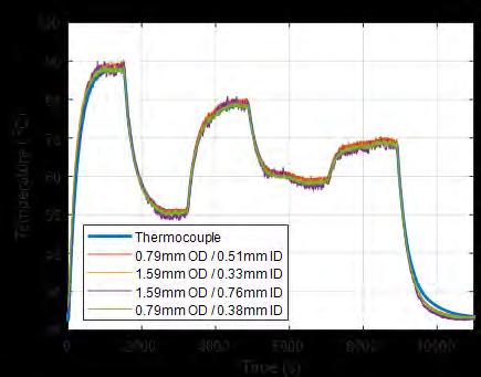
As FBGs are sensitive to both strain and temperature, to accurately measure temperature it is necessary to isolate the sensors from external strain. This can be achieved by placing the FBG inside a rigid tube. As the use case for this sensor is within a winding, it is preferable that this tube be made from a non-conductive material; PEEK has been identified as suitable candidate for this purpose.
In previous report, simulation of the transient response time of the sensors was evaluated and found to be quicker than 5s for all PEEK tube geometries under consideration. To further study this impact, and consider its effect in the context of a larger system (with its own thermal mass), samples of tubes (with different geometries) were attached to a heater plate, alongside a reference thermocouple. This plate was then driven through a series of thermal excursions to evaluate the transient response of all of the sensors. From the results shown here, it can be seen that when the thermal mass of the system is considered, the relative difference in tube thermal masses does not significantly impact the response speed of the sensors. Furthermore this testing also shows that all FBGs exhibited comparable performance to the reference thermocouple. This suggests that, within reason, the selection of PEEK tube geometry can be made based on what is most suitable for the machine winding in question.
gc 1.3: ligHt-
WeigHting And multiFunctionAl non-Ac tiVe components
The main focus of GC1.3 is to lightweight the non-active components of an electrical machine, which typically account for 45-55% of the total weight of the machine. The design optimisation for electrical machines has to date been focused primarily on the active components, with arguably less attention on the optimisation of the non-active components. A secondary consideration for GC1.3 is to design the machine components to be multifunctional, which will enable them to enhance the machine performance by providing functions such as direct cooling or sensor embedding.
A key stream of work this year has been to develop a methodology with the aim to lightweight and cost-effectively manufacture the rotor structure of electrical machine in aerospace applications. The research question that we posed was:
HoW do We de Velop A metHodology tHAt systemAticAlly includes design And mAnuFActuring constrAints into A single process?
The novelty in this work is to bring the manufacturing considerations to the initial design work stage. Traditionally, electrical machines are designed by focusing on the electrical and mechanical performance. The design is then iterated to optimise for the performance criteria, with this finalised design then passed onto a manufacturer to fabricate. Since the manufacturing constraints have not been taken into consideration during the design, it often happens that changes are required to be made to the optimised design to make it manufacturable, leading to a non-optimal machine being manufactured. By considering the manufacturing element of the process as an input variable at the design stage, not only can these post-production changes be eliminated, but benefits of the manufacturing process can be taken advantage of to produce a superior product.
The methodology begins with the identification of all possible design options through the definition of a ‘family tree’. These design options range from the standard through-shaft design, to a novel, one-piece hollow hub geometry. In order to differentiate between design choices, a first pass selection criteria was developed which conducts a trade-off between key aspects of potential manufacturing routes, including high level costing, tooling
considerations, and material properties of specific manufacturing methods. The inclusion of material data specific to manufacturing routes is a key element to this methodology as it will allow for the lightweighting of components when material strength can be increased during the manufacturing process, i.e. through the use of cold forming processes. The final step before the modelling work is undertaken is to specify key properties of the design process in relation to the chosen methods of manufacture. For example, the minimum wall thicknesses achievable, the tolerances and component runout values, and any design criteria that need to be considered, i.e. min forming radii, minimum length of component. It is important to understand these constraints prior to the design stage as it allows for the engineer to optimally design the component for a specific method of manufacture.
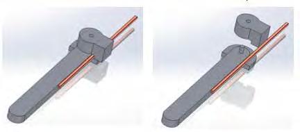
Once all the background information is collated, then the modelling work can begin. For this section of the methodology, design flowcharts have been developed to address the design requirements of the rotor structure’s statics and dynamics, including the thermal, mechanical, and electromagnetic stresses, as well as the critical speeds and rotor dynamics for safe machine operation. For the rotor dynamics, structural and bearing dominated modes will be considered. Each of the possible options will be passed through the design procedure to evaluate their optimised light-weight design in conjunction with the applicable manufacturing route most appropriate for that design. Currently, the modelling work focuses on three design options including the conventional through shaft design and novel, one-piece hollow hub geometry mentioned earlier, which are shown in Figure 1.3.1.
Key considerations are currently being evaluated for these design options, including: weight, static and dynamic loading, critical speeds, and allowable runout imbalances. Initial modelling work has been conducted on various aspects of the designs, including bearing analysis shown in Figure 1.3.2, and dynamic modelling of different hollow shaft options which is shown in Figure 1.3.3. Use of different types of materials and manufacturing methods, and the costs
Figure 1.3.1- Finite element models of potential designs for a rotor hub and shaft assembly, with the full design shown on top, and a cross-section shown on the bottom
Figure 1.3.2-
associated with each of them, needs to also be estimated for the sake of the cost-effectiveness of each design.
Initially it is attempted to complete building this design framework through carrying out the analysis for these three options. Afterwards, it is expected that other design options can also be evaluated within this framework based on the developed methodology. This methodology can then be applied for the design-integrated improvements for lighter weight electrical machine rotors.
The development of the methodology is currently in the final stages, and the completed work will be submitted to a peer-reviewed journal in April 2021. The next steps for this methodology will be to extend the work to include manufacturing focused sections, which could include cost modelling, full method of manufacture development, and the integration of process modelling results on specific manufacturing methods. There is also a plan to link this work with Grand Challenge 2.5 (Sustainable manufacturing of electrical machine components for the circular economy) to consider Life Cycle Assessments of specific rotor topologies and proposed manufacturing routes.
One aspect of electrical machine design optimisation which has received relatively little attention is the representation of the wider system implications of particular design parameters, and this has been the focus of another of the main streams of research within GC1.3. For example, an application in which there is a premium on both the power density and efficiency of the electrical machine, which are often at odds with each other. Another example is improving the performance of the electrical machine through an optimised cooling regime, with the electrical machine representing only one part of a larger problem. Aside from incremental improvements that could be made in a state-of-the-art liquid cooled machine, could a systems engineering approach be utilised to enable an air cooled machine to become
Figure 1.3.3 - Comparison of the dynamics of two novel hollow shaft rotor options, with ANSYS outputs (L) and the corresponding Campbell Diagrams (R).
competitive with a liquid cooled machine at a system level? This could potentially be achieved through intelligent system design and the development of multifunctional components to aid with air cooling. Within GC1.3 we initially framed the problem as:
For An Air cooled system to Work As eFFiciently As A liQuid cooled, it Would need to AcHie Ve certAin criterion. iF We cAn deFine tHAt criterion, tHen WHAt noVel mAnuFActuring metHods cAn be utilised to AcHie Ve tHese?
We began investigation the most appropriate methodology (or combinations thereof) to use and these included TRIZ (i.e. Theory of Inventive Problem Solving), Axiomatic Design, and Multidisciplinary Optimisation (MDO). These three options present a tiered approach to the problem, with TRIZ sitting at a conceptual stage. TRIZ is a structured brainstorming tool used for early stage, conceptual idea generation. The next step down in detail is axiomatic design, which typically develops ideas from concept to detailed stage by following set principles. Finally, MDO is the most detailed approach and is typically used when a base design exists. MDO is then used to track how changes in current design would affect other components. For all three of these methods, the first step in to define the boundary of what to include, and understand the interfaces to other systems. For this to be successful, an appropriate case study is needed to develop the work beyond a high level concept. At this point a suitable case study has not been found so this stream of work has been paused for the short term.
Until an appropriate case study can be found, the focus has been shifted- in the shorter termfrom the integration of the electrical machine in a wider system architecture to a ‘system’ that is made up of individual components and assembly requirements. The individual sections have been defined as performance, manufacturing, and assembly requirements. For the performance section, trade-offs can include efficiency, thermal management, and material improvements/degradation (through both manufacturing and in-service conditions); the manufacturing trade-offs can include manufacturing route, unit cost, lead times, and flexibility of tooling; and the integration trade-offs include component count reduction, ease of assembly, tolerance stack-up, and standard versus bespoke assembly tooling. Designing for these three objectives (performance, manufacturing, assembly) will then allow for an optimised ‘system’ to be developed.
This modelling approach could also be used in future to consider the merits of a fully standardised design versus a bespoke design. If the customisation space is considered as a continuum between standard ‘off-the-shelf’ components or machines at one end, and fully customised, bespoke machines at the other end, where is the optimal area for the design space, and what advantages make the standardisation approach more attractive? For any given application, there will be trade-offs between performance and cost, where cost in this context could include raw material, manufacturing processes, certification, maintenance, and end of life processing. This stream of work will be developing these ideas over the coming months and aiming to understand what manufacturing considerations need to be taken into account in order to optimise the production of low volume, high value electrical machines.
gc 2.1: From nominAl core properties to in-serVice perFormAnce
This work-package is concerned with providing the underpinning modelling and material characterisation to establish the impact of different manufacturing steps on the magnetic properties of the final stator core. It is widely accepted that the in-service magnetic properties of a stator core will show some degree of shortfall from the manufacturer provided material data and is often accounted for with empirical build factors, with a particular emphasis on the influence of mechanical stress and edge damage during cutting of the stator profile. The research is focussed primarily on the behaviour of high performance Cobalt Iron alloys since this is an important class of materials for high performance machines but has received considerably less attention in terms of manufacturing related behaviour than mainstream electrical steels based on Silicon Iron.
The research in the first year of the Hub was directed primarily at the modelling of compressive stresses in representative stator cores as a result of pre-stress generated through shrink-fitting of casings. This provided guidance to the range of mechanical stresses over which material characterisation would be required. Over this past year, the research has continued with some modelling of different manufacturing related stress conditions but has primarily focussed on material characterisation and the detailed design of a test-rig to perform measurements under both tensile and compressive loading.
A comprehensive test plan has been established in consultation with Carpenter Technology spanning core loss and magnetisation characterisation under standard conditions, under mechanical stress and for samples which incorporate a series of precision cuts produced by different methods to assess the aggregate effect of edge damage. This first round of characterisation is based on 300 annealed and insulated strip samples of Hiperco 50 Cobalt Iron kindly provided by Carpenter Technology (~150 samples cut in each of parallel and perpendicular orientations to the rolling direction) with additional sheets from the same batch for producing ring samples or other test pieces as required. The loss and magnetisation characterisation of the samples is being undertaken using a Laboratorio Elettrofisico AMH-1K-S soft magnetic
300 x 30x 0.15 mm test strips of Hiperco50 Cobalt Iron
permeameter alongside an EF-LF-0.4k Epstein frame and an SST100 single strip tester (both with measurement capability up to 400Hz).
Significant effort has been put into rigorous assessment of repeatability of loss measurement in an Epstein frame and, in due course, cross-correlation with single strip tester. This is providing a robust baseline of properties for the strips against which the influence of different mechanical stress conditions and cutting processes can be established. An example measured core loss for a series of parallel oriented strips at are shown below.
The nature of the data required to characterise the influence of stress on core loss is shown in the example below, which is drawn from published results at one operating point [1]. As will be apparent from the data for this combination of 400Hz sinusoidal excitation and a peak flux density of 1.8T, there is a very significant increase in the loss with compressive stress with a less pronounced variation under tension. By way of illustration of the significance of this result, taking the zero stress core loss as a 100% baseline, then in compression the rate of increase in core loss up to 100MPa for this combination of frequency and peak flux density is 1.1% increase per MPa. Modelling reported in the previous Annual Report indicated that bulk stress levels in some regions of stators can experience compressive forces of the order of 30MPa with representative shrink-fits, which in turn could result in a proportion of the stator core, notably the core-back, generating ~30% higher loss than would be predicted without consideration of stress. Given that this 400Hz operating point is likely to have a significant contribution from classical eddy current loss (which is likely to be far less sensitive to mechanical stress than the
Hiperco 50 samples on test in Epstein frame
Figure 2.1.1: Variation in loss density with stress at 1.8T, 400Hz in Cobalt Iron - date from [4]
other loss components) then this overall sensitivity of loss to compressive stress is likely to be even more pronounced at lower frequencies.
A characteristic such as that shown above is only one example of a much wider set of curves which are required to fully characterise the influence of mechanical stress core loss. A series of measurement are planned at different combinations of peak flux density, frequency and stress (and hence different proportions of loss from hysteresis, excess and classical eddy current components of loss). This will provide the underpinning data to enable machine level core loss to be calculated from an aggregation of losses in each element of the core which reflects both the localised flux density variation and the localised stress.
The key enhancement to the existing measurement system to allow controlled application of mechanical stress is the integration of an AML Z3x500 horizontally mounted universal testing machine with the SST100 single strip tester. The design of a test-rig for the precise and repeatable application of mechanical stress to a single strip is far from straightforward, particularly in terms of minimising the uncertainty in the applied stress at which the loss is measured. Whereas applying a tensile load on a thin strip is relatively straightforward, the application of compressive stress is far more challenging due to the tendency of thin strips to buckle under even modest load. In order to prevent buckling, which would occur at a small fraction of the loads of interest, it is necessary to constrain the sample in the direction of buckling. However, the normal forces which would result from contact with the constraints and the arising friction has the potential to significantly alter the localised magnitude of the stress in the sample (with potential for significant deviations from
the external measured load) and in particular the uniformity of the applied stress.
Following input from our industry partners, we initiated a mechanical finite element study of the buckling and frictional effects in the proposed arrangement in order to design the supporting structures and quantify the influence of friction on the localised stress in the region of the sample which contributes to the measured volumetric loss density. This analysis has considered the forces required to initiate various buckling modes, the impact of the clearance between the single strip and the letterbox type slot in the heart of the single-strip tester, the location and arrangement of clamping supports along the length of the strip to avoid localised buckling (which can occur in gaps as short as 10mm under high loads) and the variation in applied stress along the length of the strip due to various levels of friction between the strip and clamping supports. By way of some illustrative examples, the variation in stress throughout the sample if the 0.15mm strip is allowed to buckle within the 105mm long and 0.8mm tall slot in the single-strip tester. As is commonplace, the deformation shown is scaled by a factor of 100 to aid clarity. The influence of bucking in the central unsupported region of strip (unsupported until the buckling strip makes contact with the wall of the slot as in this case) has a very marked effect on the stress distribution in the region in which the loss measurement is taken. If the strip is prevented from buckling by being in contact with a stiff supporting structure (including a packing strip in the slot of the single-strip tester) then, as would be expected, the coefficient of friction is critical in determining the variation in stress along the length of the strip. By way of example, the second stress distribution shows the axial variation in stress for a 10N load applied at one end of the strip due to accumulation of reactive forces resulting from friction with the supports. This analysis has informed the design of the test-rig, the main elements of which are due for delivery imminently and when supported by strain gauge measurements will provide a well-founded basis for quantifying the uncertainties in the stress variations in this kind of test-rig.
gc 2.2: mAnuFAc turing HigH perFormAnce coils And ultimAte
c ontrol
This work-package is focussed on advanced coil manufacturing techniques, in particular those which have the potential to realise high performance coils though a combination of innovation in conductor configurations and their manufacture with precision and repeatability. This work-package links closely with GC2.3 and GC2.4 which are concerned with flexible automation and in-process monitoring respectively.
The experimental validation of the thermal performance of the oil-cooled hollow conductors has been hindered by the restrictions on laboratory access that have been in place over the past year. Nevertheless, progress has been made on designing, manufacturing and commissioning a test-rig for validating the heat-transfer capability and pressure drop behaviour of a representative sample of conductor. The figure below shows the manufactured test-rig which includes custom electrical and fluid connectors and this rig will be used in the coming months to validate the modelling undertaken on hollow conductors.
A key development in the past year has been research on the manufacturing challenges of coils with solid bar type conductor where precise control of the individual position of each turn is required in order to achieve the high packing factor. Research has been initiated on the
mechanics of forming coils from insulated copper bar, in terms of forces required, the limits on strain and behaviour such as spring-back. Investigations to date have focused predominantly on forming of coils with hollow core conductors as these pose additional challenges such duct deformation. However, much of the research has direct read-across to more conventional solid cross-section conductors.
A room-temperature stress-strain curve was measured on a 4x4mm copper conductor with a 2mm circular duct (temper as supplied by manufacturer) and is shown below. To provide some context for this stress-strain characteristic, it is instructive to consider the degree of strain which is likely to be encountered in a typical formed coil. Taking the 4x4mm hollow conductor as an example, the manufacturer recommended minimum bend radius is 12mm, this being three time the conductor width. This is a relatively gentle curvature for a coil and this bend radius is in part a consequence of the hollow core. For this minimum bend radius, the tensile strain at the outer edge of the curved conductor is 14% which as will be apparent is well into the plastic deformation range, as would be expected if the coil is to retain much of its imposed geometry when the tension applied during winding is removed.
The demonstrator machine with a complex distributed hollowconductor winding described in the 2020 Annual report remains a long-term focus of GC2.2, but as an intermediate step, a more straightforward racetrack type coil has been studied in terms of the forming mechanics and jig design. Adopting for the time being, the manufacturer recommended minimum bend radius of 12mm for the 4x4mm hollow conductor results in a race-track type coil that would fit onto a tooth of ~22-23mm wide, which necessarily restricts considerations to large machines. To this end, an existing design of a 250kW air cooled electrical machine designed as a direct-drive generator [5] has provided a meaningful case study to determine a baseline hollow conductor coil topology and initiate the manufacturing study. The existing design reported in [5] is based on a forced-air cooled winding which operates at a modest rms current density of 5.62A/mm2. The current case study seeks to demonstrate the potential for significant reductions in active machine volume and mass which can be realised by operating the stator conductors at much higher current densities.
The baseline hollow conductor coil design is a concentrated, so called racetrack coil design, which fits around a single tooth of the stator core and is located within a pair of parallelsided slots. As will be evident form the general view of the stator, each slot only contains conductors from one coil. The axial length and width of each stator tooth is 185mm and 22mm respectively.
A single coil, comprised of a 4x4mm hollow conductor (2mm central circular duct) wound with eight turns, occupies each slot in this particular stator. The coil itself comprises two layers, each with 4 turns and hence the conductor path needs to change layers between turns 4 and 5. A machine based on this coil design results in a reduction in the stator slot depth from 47.5mm in the original air-cooled design to 11mm with a consequent mass reduction in the stator from 93.3kg to 50.1kg. However, to realise this significant mass reduction while maintaining the rated torque, the hollow conductors would need to operate at an rms current density of 25.28A/mm2. This is a value which previous modelling (detailed in 2020 Annual Report) suggests is achievable from the perspective of temperature rise, albeit at a significantly reduced efficiency.
Producing a controlled coil geometry from a hollow conductor, even a simple racetrack soil with a high level of precision and automation, poses several manufacturing challenges, such as forming of successive bends at increasing radii, maintaining tension in the winding and managing the level of spring-back when mechanical constraints are removed post forming. As would be expected, deformation of the conductor cross-section and the central duct is strongly influenced by bend radius. Maintaining the geometry and integrity of the central duct is critical, in order to prevent both additional pressure loss in the coolant and any loss of effectiveness in heat removal from the conductor.
The close packing of the square hollow conductors within each slot means that changes in layer can only occur in the end winding regions of the coil. The span over which this layer change can occur is therefore a function of the tooth width and / or the position of the turn within the coil where the layer change is required. This is of particular significance in small to medium sized electrical machine stators where the tooth width approaches the limitations of minimum bend radius for the conductor, in order to maintain the duct. A series of analytical and 3D FEA structural models have been developed to study the bend forming process for a range of bend radii. The modelling scenario represents a forming process akin to pipe bending, where the required bend in the conductor is produced using a former in which a pivoted moving element forces the conductor around a semi-circular path.
The geometry of the former is representative of the stator tooth, with an additional radius over
CAD model of modified 20 pole stator
Proposed racetrack coil geometry
Proposed former for simple in-plane 180° bends
which the end-winding feature of the coil is formed. Prior knowledge of force or torque magnitudes required to form bends in the hollow conductor and maintain the necessary tension will inform the development of an automated manufacturing solution. Indicative predictions of Stress and plastic Strain distributions of formed 180° bends with 12mm and 6mm radii, using annealed copper physical property data, are shown. The data suggests a level of spring-back of 0.16% within this bend. A cross-section through the formed bend (90° angle) is shown for 3mm, 12mm and 24mm bend radii and clearly show the deformation of the conductor and hollow core that is likely to occur without adequate support during the bend forming process. Investigations into potential support mechanisms for the conductor and duct are ongoing, which include external support on the internal radius of the conductor and the use of a filler material in the duct whilst forming. The bend forming models will allow determination of the modulus required from a support material in order to provide support to the duct during forming. Furthermore, the impact of duct deformation on pressure loss can be assessed.
An automated coil manufacturing process, where precision placement of the conductor within the coil is achieved, is being developed in collaboration with the robotic winding facility at the AMRC. An initial concept has focused around pre-forming of the layer change feature, which is either formed prior to winding the conductor on to the spool or, where multiple layer changes are necessary, or formed in the conductor as the coil is wound. In the case of the baseline 2-layer eight-turn racetrack coil, the layer change feature would be located in the former prior to commencing winding. Robotic arms complete the winding process for each layer and add and remove inserts, which ensure the conductor remains on the intended plane. A method for controlled removal of the coil from former while retaining tension in the coil followed by direct placement into the stator is currently in development.
gc 2.3: mAnuFAc turing tecHnologies For Flexibility And customisAtion
robotic coil Winding And mAcHine Assembly
Grand Challenge 2.3 focuses on opportunities and enabling technologies for flexible manufacture; bringing the benefits of automation, such as improved quality and traceability to low volume production of high value electrical machines. Work over this second year of the Hub has focused on establishing the hardware for research into remote laser cutting, and robotic coil winding.
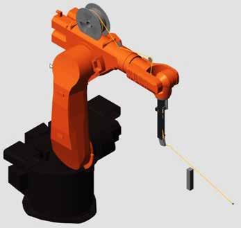
Industrial robots can be tailored to a wide variety of manufacturing processes by changing the end-effector (tool) attached to it, and as such, would be well suited as the basis of a flexible manufacturing system where the variety of products or low production volumes make dedicated automation prohibitively expensive. Indeed, in the area of electrical machines manufacture, the AMRC recently demonstrated the placement of high-strength permanent magnets on large rotors for off-shore wind power generation through the ROBOMAG project with Magnomatics.
In Q3 of 2020, twin KUKA KR 60 HA robots were installed at AMRC Factory 2050 (Figure 2.3.1). These robots feature a 60 kg payload to allow handling of completed machines and provide the requisite stiffness for coil winding. The robots are capable of working in synchronous motion, e.g. moving the stator relative to the needle or for collaborative trickle insertion of preformed coils, and modulating the movement based on an external feedback such as wire tension.
A bespoke needle winding endeffector, shown in Figure 2.3.2, has been design and manufactured
Figure 2.3.1- AMRC team (Left to right: Gianmarco Pisanelli, Dr Lloyd Tinkler and Dr Alexei Winter) and twin KR 60 HA robots at the Factory 2050
which features in-line measurement of the wire tension, and an articulating needle to provide access to the bottom face of stator and continuous control over the angle of the wire leaving the needle. The end-effector will be fed by a servomotor wire tensioning system developed by Aumann who specialise in equipment for the manufacture of electrical machines. This will allow the pay-out of the wire to be coordinated with the movement of the robot and articulating needle to minimise variations in tension as the coil is formed.
A key step to coordinating the various moving elements and understanding their influence on wire tension is creating a faithful model of the winding process. Figure 2.3.3 shows a screenshot of the winding process simulated using Simulink’s Simscape Multibody package. This provides a low-level physics simulation of the robot and end-effector as a series of rigid bodies with linked kinematics as well as simulation of the wire as a flexible body. Importantly this simulation will be linked to the Beckhoff TwinCAT programmable logic controller to be used to coordinate motion of the robot, end-effector and servomotor tensioner to provide a Digital Twin of the process.
At the time of writing, the manufacture of the needle winding end-effector has been completed, and the team is awaiting delivery of a control cabinet before starting the winding of concentrated coils. The aim of the next quarter is to make the first demonstration of orthocyclic winding using such a serial arm robot. Thereafter the influence of wire angle at the output of the needle on friction, and thus wire tension, and subsequent damage to the wire insulation will be investigated.
Future plans are to develop a bending end-effector for the forming of solid or hollow conductor coils to support development in Grand Challenge 2.2.
remote l Aser cutting
Laser cutting lends itself naturally to flexible manufacture, and in contrast to stamping, allows each product and indeed each lamina to be unique, opening the possibility for exotic pseudo-three dimensional (so called 2.5D) laminated cores. However, laser cutting is typically restricted to prototype or low volume manufacture due to the low throughput when compared to stamping. As such, machine designers cannot fully exploit the flexibility offered by laser cutting without compromising the design for future scale-up in production.
Figure 2.3.3 - Simulation of coil winding process using Simulink Simscape Multibody
Figure 2.3.2 - Robotic needle winding end-effector mounted on KUKA KR 60 HA (left) and articulating needle approaching 3D printed stator segment to be used in testing.
Remote laser cutting has been proposed as an alternative approach with the potential for higher cutting speed whilst minimising thermal damage and the associated increase in core losses at the cut edge. Over the last year AMRC has continued the development of the remote laser cutting cell with the build underway and commissioning in the coming months. Figure 4 shows the enclosure installed at AMRC Factory 2050 and the electrical control cabinet under construction. The system will feature a 2 kW fibre laser steered by a high-speed galvanometer. The movement of the galvanometer will be synchronised to two linear stages to overcome the limited field of view. This will allow large movements and slow changes in direction will be handled by the linear stages whilst sharp features such as stator teeth will be traced by the galvanometer.
A further challenge to the use of laser cutting at even moderate production volumes is automating the unloading of the cut parts. Fusion laser cutting requires an inert shield gas to cool the workpiece and eject molten material from the kerf. However, thin electrical steel sheets can be sufficiently light that the cut part must be held in place by tabs connecting it to the waste to prevent it being lifted from the surface by the shield gas. This then necessitates a secondary manual process to break the tabs before stacking the lamina. To overcome this challenge, the workpiece will be held by a vacuum chuck, avoiding the need for tabs. A custom end-effector, FLEXeMAG shown Figure 2.3.5, has been developed that features an array of individually addressable electromagnets, to allow the robot integrated into the cell to separate the cut parts from the waste material for automated loading and unloading.
In an aligned High-Value Manufacturing CATAPULT funded project, custom tooling is being manufactured for the pressing of laminated stacks which will enable research into the production of 2.5D stators. This shown in Figure 2.3.6. The tooling will be equipped with high-temperature load cells to allow investigation of the influence of the load applied before and during pressing on the core integrity and losses.
Figure 2.3.5 - FLEXeMAG end-effector showing the array of individually addressable electromagnets
Figure 2.3.6 - Concept 2.5D stator (L) showing rounded teeth to aid winding, skew, and through holes without breaking individual layers; and the pressing tool (R).
Figure 2.3.4 Remote laser system enclosure (L) and control cabinet build (R)
gc 2.4: in-process trAcking And trAc tAbility For zero-deFect mAnuFAc ture
oF electricAl mAcHines.
The manufacture of electrical machines is a complex task, involving the synthesis of many traditional machining/forming and cutting processes interspersed with assembly, integration and test. Across this manufacturing lifecycle there is input from skilled manual processes that ultimately impact the quality of the end product and its performance over the duration of its service. This work-package is concerned with developing an understanding of these activities and their variations, and the scope to digitise these processes so as to allow in-process tracking and traceability for defect detection, mitigation and certification at the point of manufacture.
The manufacture of electrical machines is a complex task, involving the synthesis of many traditional machining/forming and cutting processes interspersed with assembly, integration and test. Across this manufacturing lifecycle, there exist both automated and skilled manual processes that ultimately impact the quality of the end product and its performance. It is our aim to understand these processes and their variations, and to digitise these processes so as to allow in-process tracking and traceability for defect detection, mitigation and certification at the point of manufacture.
1. industry surVey
To understand the degree of manual activities in process monitoring within electrical machine manufacture, a structured survey of UK based companies was conducted to identify specific error prone manual processes and gaps in inspection. The survey identified that a significant proportion of activities in electrical machine manufacture are manual or semi-automated with manual interventions. However, literature review revealed only a limited research in this area. These findings have been submitted as a journal article.
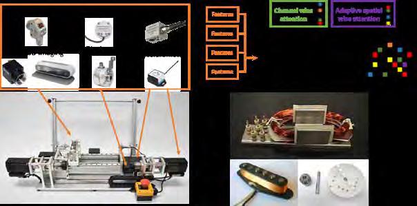
2. coil Winding: process monitoring
To investigate coil winding and forming processes, we have sensorised a commercially available coil winding system, identifying several areas in which to gather both IoT sensor data and images during the coil winding process (wire tension, spool, motor speed, torque, vibration, etc). Using this wealth of information, we are looking at how we can develop and apply sensor fusion techniques adapted from the state-of-the-art field of Deep Neural Networks (DNNs) to
track process variation in real-time and identify deviations, anomalies or faults as they occur.
To this endeavour, we are developing an attention-based approach based upon the recent success of the ‘Transformer’ networks within DNNs. Here, not only do we wish to extract features from the data and perform fusion across all inputs to improve accuracy, but also utilise the attentionbased approach to allow us to identify what feature or information is being used to classify or track any deviations or anomalies as they occur. This allows the model to selectively attend to the information it feels is the most important with the goal of allowing it to better track the process in real-time and identify anomalous behaviour / process variation. An outline of the overall sensorised workbench and sensor fusion attention-based framework can be seen in figure 2.4.1.
A challenge within many machine vision systems is the need for a suitable amount of material (images) to train the models to perform object detection, segmentation, fault classification, anomaly detection, activity recognition etc. In manufacturing, this is even more of a challenge given that access to images of failure can be rare. To combat this, we are investigating the use of both generative models, such as the popular Generative Adversarial Networks (GAN) architecture, and one-shot learning methods for enabling fault classification and process monitoring with limited data. We are investigating a number of state-of-the-art generative models, in particular that of the popular StyleGAN2 architecture, as a means to generate images of coil failure to augment our current datasets and provide more data to improve the accuracy of our trained classification models. An example can be seen in figure 2.4.2, where the outputs of the trained model evolve over time to reproduce examples of our failure classes, which we can then use to augment our dataset. This research has produced a paper on generative models for improving classification and anomaly detection in electrical machine manufacturing processes. An alternative approach to
Figure 2.4.2 - StyleGAN2 generated images over training time for coil winding failures
the lack of data is to try and create through ‘synthetic’ means images or data which can act as a facsimile to the real thing. Here, we are investigating how 3D modelling tools such as Blender can be used to automatically generate images of cables, wires and coils, that contain the necessary labelled and segmented data we need to train our models. This has allowed us to generate tens of thousands of images which would not be possible manually.
3. terminAtions: process monitoring And inspection
The joining of insulated copper wires with connectors or cable lugs is one major reason for motor failures. The process of joining or making terminations can be divided into two main process steps: enamel removal process which ensures that wire insulation in the joining zone is removed and contacting process which makes a connection. The focus of this research is on Litz wires, which are special types of cables that are designed to reduce the skin effect and proximity effect losses in conductors. Litz wires consist of many thin wire strands, individually insulated and twisted together. A review of literature and discussions with industry revealed that up to 10% of Litz wires have failed connections due to incomplete stripping of some strands inside the connector. Therefore, infrared thermography was investigated as a non-contact, non-destructive process for inspection of enamel removal of Litz wires. A bundle of Litz wires containing wires with enamel fully intact, partially removed and fully removed were gently heated for 10 seconds and then cooled, and the infrared images were recorded. Figure 2.4.4 displays the infrared images of Litz wires during a heating and cooling cycle, where bright areas represent higher temperatures. In Figure 2.4.4, the wire labelled as 1 had enamel completely removed and therefore had Copper on the surface, wire 2 had enamel (polyamide imide) coating on the surface, and wire 3 had enamel partially removed.
The temperature profiles of the three wires were different during the cooling stage; wire 1 cooled faster than enamel coated wires 2 and 3. This is because the emissivity of copper and polyamide imide film are approximately 0.2 and 0.9 respectively. Figure 2.4.5 demonstrates the absolute temperature profiles of wire 1 (copper) and 2 (polyamide imide); normalised graphs of the two wires during the cooling cycle are shown in the inset.
Figure 2.4.3 - 3D modelling of cables and wires: (A) real example, (B) 3D model, (C) image segmentation, (D) depth map imaging, (E) coil and sensor wire modelling
Figure 2.4.4 - Infrared images of three Litz wires (labelled 1,2 and 3) from a bundle during a heating and cooling cycle
Figure 2.4.5 - Temperature profiles of copper and Polyamide Imide (PI) coated wires during the heating and cooling stages; graph in inset shows the normalised graph for cooling
Image processing techniques were then used to identify the regions with and without enamel coating. Canny edge detection algorithm was used to detect the wires in the infrared images and then the generated mask of edges was dilated to separate the wires from the background (Figure 2.4.6). Current work is focusing on algorithms for segmenting an image into smaller regions or super pixels, an example is Simple Linear Iterative Clustering algorithm that groups pixels based on their physical and colour proximity. This will allow automated identification of regions with and without enamel. Future work will involve investigation into machine learning algorithms for automated inspection.
4. terminAtions: trAcking And trAce Ability
The manufacturing process of electrical machines contains numerous steps and activities that involve the use of deformable materials. These include enamelled copper wires, insulation materials, and cables associated with sensors and connections/terminations. These Deformable Linear Objects (DLOs) are a challenge when it comes to automation and process monitoring, as their deformable nature make it difficult to extract suitable parameters or models in which to base further actions / decisions. This year we have been continuing along this thread of research with a look into how we can apply current state-of-the-art methods in deep learning and machine vision to track and trace these deformable linear objects (wires and cables) within activities of electrical machine manufacture. Recent advances in object detection, image segmentation and 3D modelling mean it is possible to develop systems that can extract in real-time the position and shape of deformable linear objects and use this information for process monitoring, anomaly detection or guidance.
To begin with, we developed a video and image dataset coined ‘CableHands’ which contains over 30GB+ of data across 5 different activities and assembly tasks derived from the connections and terminations steps of electrical machine manufacture. This dataset includes standard RGB (Red Green Blue), depth and motion capture data along with bounding box and segmentation information for hands and cables. This allowed us to develop machine vision models for real-time 3D modelling of hands, cables and their interactions, and parametrise these models to better identify anomalies and incorrect actions. The process involves identifying the objects of interest, in this case both the operators hands and the DLO/cable, and using this information to build a 3D model as shown in Figure 2.4.7 for the hand modelling component.
Figure 2.4.6 -(L) Infrared image of heated wires (C) Masked image using Canny edge detection algorithm (R) Image obtained using Simple Linear Iterative Clustering
Figure 2.4.7: Hand modelling framework - Beginning with object detection (hands), we build a skeleton model and then fit a SIMPL-X hand model to project to three dimensions
gc 2.5: sustAinAble mAnuFAc turing
oF electricAl mAcHine components For
tHe circul Ar economy
During 2020, a new work package was developed within the FEMM hub focused on the sustainable manufacture of electrical machine components, with a view to implementing circular economy strategies. This work package aims to discover, assess and implement alternative, more sustainable routes for the entire life cycle of the electrical machine components, and aim to loop the materials back into manufacture at the end of the component life (i.e. develop a circular economy approach).
In order to do this, several key challenges will be addressed which are:
• cHAllenge 1 - develop a sustainable manufacturing model for electrical machine components
• cHAllenge 2 - detail potential reuse, remanufacture, refurbishment and recycling options of current electrical machine materials, and develop a ‘flow down’ quality chart detailing where recycled materials could be utilised.
• cHAllenge 3 - of in-service data and data-driven intelligence to select the most appropriate circular economy strategies for products and the timings of intervention in the product lifecycle, e.g. define the appropriate circular economy intervention (reuse, remanufacture, refurbishment and recycling) which is best applied, and at which particular point in time.
• cHAllenge 4 - begin developing a UK supply chain for the end of life processing (remanufacture/ recycling) of current and future machines.
• cHAllenge 5 - collaborate with UK based companies to develop case studies for improvements on recycling of materials/components (i.e. rewinding of stators, testing of machines).
GC2.5 kicked off fully in January 2021, and there are currently two main streams of work. The first is a literature review which is focusing on circular economy approaches for electrical machines. The review will aim to summarise the current research strands and trends, and highlight gaps in the current knowledge in order to devise a future research direction.
A review of literature from last five years suggests the key focus areas for research in circular strategies in electrical machines, summarised in Figure 2.5.1. As demonstrated in Figure 2.5.1, recycle, which is an end-of-product-life strategy, is the focus of a significant numbers of papers. Remanufacture, which falls within the circular strategy of product life extension, is the
process of disassembling and recovering an asset at a product and component level, and is the second most researched area. Finally, reuse, which is also a circular strategy of product life extension, is a relatively less researched area for electrical machines. Reuse is a better strategy in terms of waste hierarchy, but may not be a feasible option due to a lack of information concerning the condition and history of a product, and also the availability of returned products. Figure 2.5.2, demonstrates the focus of recycling of several components of electric motors. Recycling of rare earth magnets is a topic of significant research interest, mainly focussing on how the production of rare earth magnets can be brought in line with the global sustainable transition. Research interests in recycling of other components of an electric motor are also represented in the literature.
The emergence and increasing uptake of technologies based on the principles of Industry 4.0 present a way to overcome some of the barriers associated with to lack of information concerning the condition of returned product, and to aid in the full implementation of circular economy principles for electrical machines. Pairing the digital revolution with the principles of a circular economy model has the potential to radically transform the industrial landscape and its relationship to materials and finite resources, thus unlocking additional value for the manufacturing sector.
The second work stream is currently focused on conducting an industrial review to understand the current landscape within the UK for repair, remanufacture, and recycling of electrical machines. The main aim of this survey is to identify the gaps within the UK in this area, and for the FEMM hub to help develop new opportunities for UK based companies. This review is targeted at two main groups: firstly, companies already working with electrical machines with a view of extending their current capabilities into repair and remanufacture activities; and secondly, companies that are involved with circular economy activities who would like to transition into the electrical machine space. Linking the knowledge and expertise from these two groups will be crucial for the development and adoption of circular economy practices for electrical machines.
Going forward in 2021, GC2.5 will be pursuing collaboration opportunities with the other FEMM hub grand challenge topics including the recyclability of soft magnetic composites, the effect of modular design on the maintenance and repair strategies of electrical machines, and opportunities for automated disassembly. Some of these topics will be researched within GC2.5 and others will naturally lead to break out projects. Whatever the route to implementation of this topics, GC2.5 aims to bring a sustainable focus to all aspects of future electrical machines.
Figure 2.5.1- Focus of literature in circular strategies in electrical machine components
Figure 2.5.2- Focus of literature in recycling of components of electric motors
pHdstudents.
optimisAtion
oF coil
Winding joHn mckAy - uniVersity oF strAtHclyde
The project involves the manufacture of novel high-performance coil geometries using additive manufacturing to enable new design methodologies. The coil geometries will be optimised and the design space will be explored using optimisation techniques such as genetic algorithms to propose potential coil structures that outperform traditionally wound copper and aluminium coils.
With the design freedoms afforded by the additive manufacturing of copper and aluminium, the project aims to deliver high performance novel coil structures that are unlike traditional coils in terms of their design.
The aim of this approach is to use the strengths of AM to enable the creation of a coil that has increased, current densities, flux densities, reduced losses, greater performance and higher efficiency whilst taking into consideration parameters such as weight and cost.
The project has been split into 3 phases, each phase containing simulation work intended to build towards the final full 3D analysis which will generate the final 3D coil geometries meant for manufacture.
A selection of coil geometries will then be manufactured using the additive manufacturing of copper, that will then be studied and analysed to understand the properties of the structures and why they potentially generate performance advantages over traditional wound copper and aluminium coils.
Leigh’s PhD is concerned with the sustainability of PMEMs, with a primary focus on the entire life cycle of the active components. The intention of this research is to develop a framework to bridge the gap between current practices and the optimal circular economy approach, which would ideally be adopted within industry but is difficult to attain. To enable this, there will be a full assessment of the potential best practices and technologies which could be incorporated to progress towards a sustainable, closed loop manufacturing system of PMEMs. Currently she is working on developing and defining the framework approach in order to progress with life cycle analysis and technology review.
iot And sensor communicAtion For in-process inspection oF complex
mAnuFActuring tAsks
ze zHAng - uniVersity oF sHeFField
Ze’s PhD will develop a deep learning-based multi-sensor inspection framework to improve the traceability of winding processes and reduce the need for end-of-line tests. It is difficult to utilise traditional statistics based sensor fusion for winding processes because the data generated by multiple sensor types could be significantly different in quantities, structures, sampling rates and information contents. Deep learning-based fusion methods have the potential to deal with these problems and learn features automatically. However, low interpretability, limited available data, long inference time and high training costs create barriers in the use of deep learning-based multi-sensor inspection in manufacturing.
Currently, this PhD is making efforts towards improving the interpretability and reducing the inference time for utilising deep learning for winding processes. The research is developing an inference mechanism from natural language processing which has proven to mitigate the issue of interpretability. A winding faults inspection framework is also being developed to give accurate and traceable detection with a short inference time. This work will be tested on a real coil winder.
ligHt WeigHt design And mAnuFActure oF electricAl mAcHine components
cHArlie scott - uniVersity oF strAtHclyde
Charlie's PhD is focused on the optimal design of non-active components of electric machines. Typically, these components account for 45-55% of the weight of the total machine, and there has been very little research conducted on their optimal design and potential weight savings. Charlie is researching two main themes in his PhD: lightweighting of the casings and end-caps, and designing a casing which can allow air cooling to compete with liquid cooling technologies. For the lightweighting stream of work, the non-active components are to be designed around a hollow coil machine with centralised cooling, which opens up new design and manufacturing options for the casings. Without the need for this casing to have advanced cooling techniques, the design focus can be on drastically reducing the weight while ensuring mechanical stiffness. For the air-cooled aspect of the work, Charlie is focusing on novel manufacturing techniques which could provide opportunities to remove liquid cooling (and all the associated weight) from a machine while achieving the same performance with an air-cooled casing.
Fibre-optic brAgg grAting sensor For in-serVice And process monitoring
HAo cHen - uniVersity oF sHeFField
Hao’s PhD project is aimed at exploring the utilisation of FBG sensors in electric machine condition monitoring, with a particular focus on developing effective means of using realtime measured winding deformation/vibration to indicate winding deterioration / faults and hence better predict lifetime. He is also developing multi-physics based condition monitoring techniques that exploit the capabilities of FBG to precisely measure thermal and mechanical in a distributed manner throughout the winding. Currently, he is working on finite element based simulation of stress/strain behaviour of winding insulation coating and aspects of integrating FBG sensor into coils.
electric VeHicles ji Qi - uniVersity oF sHeFField
Ji ’s PhD project is concerned with the design of high-performance hub machines for electrical vehicles. Currently, the project is focusing on the design of consequent pole (CP) permanent magnet machines.
Due to the unipolar magnets in rotor, CP rotor can produce unipolar end shaft flux leakage, which will cause magnetization risks to mechanical components. Besides, the unbalanced Northpole and South-pole will lead to large even order harmonics and consequently large torque ripple. Therefore, same amount of North-pole and South-pole magnets are placed in rotor to solve the problems and maintain the high ratio of average torque to PM amount of CP structures.
According to the Finite Element Method (FEM) simulation results, the proposed modular rotor CP machine can achieve almost the same average torque as the conventional one, while it can eliminate the end shaft flux leakage and reduce the torque ripple from 42% to 22%. Compared with the SPM counterpart, the ratio of average torque to PM amount for the proposed machine can be increased from 2.66×10⁵ to 3.55×10⁵ Nm/m3. However, large number of magnets of the modular machine will also lead to high cost, which will be analysed in future work.
metAllic contAinment slee Ves For pm mAcHines
dAniel HArper - uniVersity oF sHeFField
Dan’s PhD is concerned with the design, analysis, manufacture and testing of metallic containment sleeves for permanent magnet machine rotors. His research has a particular focus on high power density and high-speed machines for aerospace applications. The multi-disciplinary project encompasses material selection and the modelling of electromagnetic, mechanical and thermal behaviour of metallic sleeves with a view to establishing combinations of materials, geometry and manufacturing processes that result in optimal sleeve designs for long-term service.
This project is concerned with research at the nexus of machine design, material modelling and manufacturing process development. The research is focused on the research challenges associated with employing high-performance Cobalt-Iron soft magnetic alloys in next-generation aerospace propulsion machines. Although offering the highest levels of magnetic performance, these alloys are stress-sensitive and difficult to process following heat treatment. This project, which will be performed in collaboration with Rolls-Royce will explore the design for manufacture aspects of machines to exploit these properties in the context of hybrid propulsion systems for next-generation aircraft.
1st Fe Asibility cAll.
We launched our 1st Feasibility Call in August 2020 to support Feasibility Studies at TRLs 1-3. We received 11 proposals across a broad spectrum of topics, following an extensive review and ranking process involving our IAB and SAB the following proposals were selected:
Hippes – HigH perForming And processible electricAl steels
The performance of e-machines is affected by many aspects, with the materials being used for the rotor and stator being important in influencing the torque generated and losses during operation. Electrical steels are widely used for e-machines and are based on a binary Fe-Si composition with minor other alloying additions and processed to achieve a non-grain orientated (NGO) microstructure. Whilst this material offers good properties / price, development of electrical steels has remained relatively limited with small improvements in performance based on better texture control. However, in recent years further binary based Fe-Si alloys have been produced in the laboratory with a Fe-6.5Si having been shown to offer superior properties particularly for high speed motors. However, this steel is not processable in conventional steel plants due to its low ductility, requiring an expensive vapour deposition / heat treatment process to diffuse Si into the strip. The resultant material is inherently brittle making it more challenging to manufacture into laminations than Fe-3 Si steel. Whilst other metal alloys, such as Fe-Co systems, are also available for high speed / high performance e-machines there is a need for improved performance low cost electrical steels.
This project acts to remove the shackles of the binary Fe-Si based approach in electrical steel development, and to show the potential of new alloys that can give a dramatic improvement in core properties, matching, or exceeding, the characteristics of Fe-6.5Si. The aim of the work is to carry out a proof of concept approach to developing a new family of electrical steels with improved magnetic / electrical properties whilst being processable using current commercial production routes. The initial approach is to match the magnetic / electrical properties of Fe-6.5 Si steel with significantly enhanced processability e.g. high ductility.
This will be achieved through the following objectives:
• Use of fundamental scientific principles, thermodynamic and kinetic prediction tools to investigate the compositional space for electrical steels.
• Use of the WMG Rapid Alloy Production (RAP) facility to cast (see above), roll, heat treat and produce final strip product of both a current (for benchmarking) and a novel ultra-high performing electrical steel.
• Use of magnetic and electrical testing to assess the performance of the new steel compared to current grades according to industry standards.
• Use of e-machine FE model to determine the potential performance benefit of the new steel.
The work will involve experts from the Advanced Steel Research Centre (ASRC) and the Electric Machines Research Group (EMRG) from WMG, University of Warwick.
Vacuum induction melting for production of bespoke steel compositions of 4.5 – 7 kg ingot size (left) and casting of small (approximately 1 kg) ingots in air (right).
AdditiVe mAnuFActuring For next generAtion FunctionAl integrAtion oF Windings
And tHermAl mAnAgement in Future electricAl mAcHines
Step changes in electrical machine (e-machine) performance in terms of efficiency, power-density and torquedensity are central to the success of future More-Electric and All-Electric transport initiatives. These changes play a vital role in decarbonisation efforts and in meeting the UK’s Net Zero Emissions target by 2050.
The performance of an electrical machine is ultimately limited by the ability to dissipate internally generated losses, manifesting as heat, and the temperature rating of the electrical insulation system. At present, the electrical windings are a major performance bottleneck, hence, improvement in their design and functionality could unlock these step changes.
WHy is it importAnt?
The Aerospace Technology Institute (ATI) and Advanced Propulsion Centre (APC) technology roadmaps envisage future elimination of conventional winding processes and functional integration as key to removing the bottleneck and achieving the necessary performance goals toward 2035.
A promising approach is to adopt metal Additive Manufacturing (AM), in which feedstock or powdered material is selectively bonded in a succession of 2D layers to incrementally form a 3D part and produce windings with unmatched geometric freedom. The design flexibility on offer has great potential in realising high-performance, high-value, customisable, low-volume windings applicable to vehicle traction, aerospace and eVTOL systems among others.
WHAt Will tHe project demonstrAte?
This project aims to demonstrate the design flexibility and close functional integration possibilities afforded by metal AM through the realisation of a low Technology Readiness Level (TRL) 3-phase concentrated winding and integrated cooled star-point concept, as illustrated below. The coils will be manufactured in copper or copper alloy by a Powder Bed Fusion (PBF) technique in collaboration with two industrial partners.
The viability of cooing coils through an integrated star-point will be assessed alongside a 3-phase set of coils, each of which will showcase a different set of integrated design features including:
• Shaped profile windings (nonuniform conductors)
• Sculpted, minimal volume endwindings
• Through conductor fluid cooling
• Splayed end-windings to enhance heat extraction (via natural convection or impingement cooling)
• Integrated terminals/fluid couplings
• Integrated sensors (thermocouples, current shunt)
If successful, the demonstrator will encourage conversation between manufacturers and electrical machine designers across the FEMM Hub and beyond, and could spur innovation in highly integrated traction drive solutions for low-volume, high-value markets such as performance automotive, future aerospace and eVTOL.
3-phase set of AM coils mounted on a stator section. Note: concept illustration - star point, detailed connections and fluid channels not shown.
industriAl mAnuFActure oF mArinised coils – immcoil
The marine energy environment poses substantial challenges that must be addressed if marine renewable energy technology is to proliferate. Key among these issues is the development of an efficient, adaptable electrical power take-off (PTO) system capable of coping with the highly variable forces. Furthermore, with high operation and maintenance (O&M) costs seriously affecting the competiveness of many systems, PTO’s must aim for designs with greater reliability and operational flexibility to lower associated downtimes. Developing integrated modular electrical generator topology and power electronic systems has the potential to improve system reliability and reducing repair time should faults occur. The modularity allows the system to continue operation at reduced capacity should either a fault occur or if sections are required to be removed for maintenance. Additionally, a fully flooded generator provides for a more versatile WEC design enabling a greater degree of integration compared to coupling a device to a mechanically sealed generator.
The UoE demonstrated a fully flooded machine with coils moulded into epoxy for protection, and polymer surface contact bearings were used instead of conventional bearings. The fully flooded coils showed excellent thermal performance with the winding temperature never exceeding 25°C. However, a number of faults occurred due to water ingress, which were related to the manufacturing process. A variety of protective materials are available for use within the marine environment; however, the challenge and novelty of this project comes from the manufacturing process and the operational constraints of the material once combined with an electrically active coil. Such challenges in manufacture come from volume of copper within the mould acting as a heat sink, altering the ability of the material to bond or cure uniformly throughout the blade. Fluctuating machine operational characteristics, such as those found in wave energy extraction, result in thermal cycling of windings, pulsating vibrations, variable load profiles acting on the stator assembly. The reciprocal nature of the motion in a wave device results in variable voltage and frequency waveforms at the output, with high dV/dt states across the windings from the power converter. The composite blade must be able to survive these electrical and mechanical stresses whilst maintaining protection, structural stability and efficient operation. By engaging research with industrial development and feeding real world applications and manufacturing practicalities back into product development, the UoE research team hope that the FEMM Grand Challenge 1 and 2 targets are realised.
The IMMCoil feasibility study will assess the effectiveness of various protective potting or impregnation methods for the production of stator blades for use in a fully flooded marine environment. The methods will be assessed for their industrial production merit, while confirming their ability to be integrated with electrical systems, maintain the required structural integrity, heat dissipation levels and material integrity during operation in wet and fully submerged conditions. By investigating the design and material selection of potted stator modules, we will deepen the manufacturing knowledge of the engineering team, and our manufacturing partners at QuartzElec.
mAnuFActuring oF ligHt WeigHt structurAl components For HigH perFormAnce
electricAl mAcHines by electromAgnetic pulse tecHnology (empt)
The use of composite and hybrid structures is central to lightweighting. The combination of carbon fibre reinforced plastics (CFRP) and highstrength aluminium alloys, for example, offers a remarkable potential for weight reduction. However, manufacturing of hybrid structures requires reliable techniques to join dissimilar materials, which are difficult to achieve through conventional welding techniques (impractical for joining CFRP to metals), use of adhesives (limited bond strength) or in-mould casting (slow and unsuitable for industrial scale-up).
The aim of this project is to explore the potentials and demonstrate the feasibility of electromagnetic pulse technology (EMPT) as an advanced forming and joining technology in manufacturing of lightweight composite and hybrid structures for high-performance electrical machines. Electromagnetic pulse welding is a promising solid-state joining process offering fast and reliable bonding without degradation of the base materials due to thermal effects. In this process, a high-energy magnetic field is used to accelerate a flyer workpiece towards a substrate to create a bond as a result of high-velocity impact.
A specific objective of this project is to create a proof of concept for joining of metals such as high-strength aluminium alloys to carbon fibre reinforced plastics (CFRP) by EMPT. The project fits within the theme of manufacturing-led innovation in electrical machines (Grand Challenge 1) and specifically addresses challenges in manufacturing of lightweight and multifunctional structural components.
The project will be carried out in BCAST, Brunel University London, which hosts the Future Manufacturing LiME Research Hub. BCAST is strongly focused on lightweighting research and is the UK’s leading specialist centre in EMPT. BCAST is well equipped with a wide range of facilities and expertise to support industries and to collaborate with academic partners in the area of lightweighting materials research.
Our 2nd Feasibility Call will launch in May. We have partnered with the EPSRC Future Manufacturing Hubs in Metrology, Photonics and Composites to offer up £1million in funding to support a number of feasibility studies at TRLs 1 to 3. Please see our website for more details.
Micrograph of an Al/Al joint
Schematics of EMPW
Femm Hub c onFerence
Given the global pandemic, a decision was made to move the 1st FEMM Hub conference online in November. Despite lockdown, our researchers and PhD’s have been progressing well with their research and we wanted to share their progress through a series of short presentations for interested members of the public, academics and advisory board members to view at their leisure. The virtual event was kicked off by FEMM Hub Director Professor Geraint Jewell, all 14 presentations following the introduction have been made public and can be viewed by visiting our website.
Dr David Hewitt: Manufacturing of features for inservice monitoring.
Dr Jill Miscandlon: Manufacturing of light-weight and multi-functional structural components
Professor Geraint Jewell: From nominal core properties to in-service performance
Dr Steve Forrest: Manufacturing high performance coils and ultimate control
Dr Michael Farnsworth and Dr Divya Tiwari: In-process tracking and tractability for zero-defect manufacture of electrical machines
Dr Lloyd Tinkler: Manufacturing technologies for flexibility and customisation
Dr Jill Miscandlon: Sustainable manufacturing of electrical machine components for the circular economy
Leigh Paterson: Circular Design and sustainable Manufacture of Permanent Magnet Machine Components
Ze Zhang: Multi-sensor fusion for In-Process monitoring of Electrical Machine Manufacturing
Dr Rafal Wrobel: Thermal management of electrical machines using heat pipes
Charlie Scott: Lightweight design and manufacture of electrical machine components
Ji Qi: Modular high-performance permanent magnet hub machine for electric vehicles
John McKay: Optimisation of coil winding
Femm Hub trAining And e Vents
We have shifted our meetings , events and training courses online to adapt to the current situation.
We have the following online training sessions scheduled within the next 6 months, available exclusively to our hub partners:
• Fundamentals and Latest Trends in Thermal Management of Electrical Machines (April)
• Fundamentals, Applications and Latest Family of Electrical Insulation Materials by Du Pont (May)
• Soft magnetic composites (June)
• An Introduction to Electrial Machines (September)
tHe impAct oF modern poWer electronic conVerters on mAcHine insul Ation
Professor Jiabin Wang from the Department of Electronic and Electrical Engineering, University of Sheffield kicked off the first of the FEMM Hub training sessions of 2021, presenting “The Impact of Modern Power Electronic Converters on Machine Insulation” to 96 delegates.
This training session was available exclusively to academic and industry partners of the FEMM Hub. By hosting this training virtually, it facilitated attendance from companies including Rolls-Royce, ZF Group, Siemens Gamesa, Protean Electric, Aerospace Technology Institute, University of Strathclyde Advanced Forming Research Centre, University of Strathclyde, The University of Sheffield, Newcastle University, Carpenter Technology Corporation, Dyson, Collins Aerospace and Höganäs AB.
The training course covered insulation structures and designs of typical electrical machines over a wide range of power, speed and torque ratings. The effects of impulse and high frequency PWM voltage produced by power electronic converters on voltage distributions in machine winding and insulation systems were analysed and characterised, and measures to mitigate these effects were discussed. The potentials for advanced manufacturing processes that may improve insulation systems were also highlighted.
core losses in electricAl mAcHines
On the 18th of March, Hub Director Professor Geraint Jewell led 98 delegates through his three hour training session on Iron loss in Electrical Machines which took place via WebEx. Delegates, belonging to members of our academic and industry partners joined from across the globe.
Iron losses are a critical factor in determining the power density limits and efficiency of electrical machines, in particular with the inexorable growth in demand for electrical machines operating at higher speeds and driven from variable frequency power converters. The training course presened a comprehensive review of several aspects of iron losses in electrical machines. It included discussion of material properties, underlying loss mechanisms and aspects of electromagnetics, but the principal focus was on the impact of material selection, machine design, core manufacture and operating conditions. A significant proportion of the course was an introductory and general level with no pre-requisites assumed in terms of specific electrical machine knowledge. As such, it provided a useful introduction for material scientists and engineers drawn from a wide range of disciplines who wish to open the box and peek into the many mysteries of iron loss.
untAngling tHe reQuirements oF A digitAl t Win
On the 29th of March, Jonathan Eyre, the technical lead in Digital Twin at AMRC led a one hour seminar to our hub members.
Digital twins are often mentioned in discussions but what does it mean to have a digital twin? What are the key essential parts to have a digital twin and what is just a simulation? The webinar provided an overview of the recent AMRC report Untangling the requirements of a Digital Twin collating the key cross-sectoral considerations from current implementations and how to approach the technology area. It also included an industrial case studies before opening up to questions.
Hub ne Ws
On the 29th of September, the FEMM Hub held their first online quarterly meeting. Over 25 of our researchers and advisory board members met via Webex from 10:30-3:30 for a series of presentations. Hub Director, Professor Geraint Jewell kicked off the meeting with a presentation detailing hub progress which included our successful monthly project meetings and annual report. Each of the grand challenges then presented an update for the group including our newest grand challenge project GC2.5.
He At pipes in tHermAl mAnAgement oF integrAted motor driVes
Dr Rafal Wrobel, University of Newcastle, has been successful in securing funding from the University of Newcastle’s EPSRC Impact Acceleration Account – ‘Ideas to Innovation’. These are strategic awards provided to institutions to respond to opportunities in flexible, responsive and creative ways, alighted to their institutional strategies and opportunities.
His project “Heat Pipes in Thermal Management of Integrated Motor Drives” aims to experimentally assess the use of advanced two-phase heat pipe technology in thermal management of IMDs. The research focus is placed on the hardware prototyping and testing of selected high-performance thermal management concepts incorporating custom heat pipe solutions.
ne W Ati rese ArcH grAnt in electricAl mAcHine repAir
A team from the University of Sheffield including FEMM Hub Director Geraint Jewell has been awarded funding as a partner in an Aerospace Technology Institute supported project ‘REINSTATE’ which is led by Rolls-Royce. Geraint will lead the Sheffield contribution on electrical machine repair technology and colleagues from the Department of Automatic Control and systems Engineering will lead the Sheffield contribution on engine sensors.
Femm Hub QuArterly meetings
publisHed outputs
Okorie, O., Charnley, F., Ehiagwina, A, Tiwari, D., Konstantinos Salonitis., Towards a simulationbased understanding of smart remanufacturing operations: a comparative analysis, Journal of Remanufacturing, 2020, doi: 10.1007/s13243-020-00086-8
Wrobel R., McGlen R., Opportunities and Challenges of Employing Heat-Pipes in Thermal Management of Electrical Machines, XXIV International Conference on Electrical Machines, ICEM 2020, Gothenburg, Sweden, 23 – 26 August 2020, pp. 1-8.
Wrobel R. and D. Reay, "A Feasibility Study of Heat Pipes for Thermal Management of Electrical Machines," 2020 IEEE Energy Conversion Congress and Exposition (ECCE), Detroit, MI, USA, 2020, pp. 4230-4237, doi: 10.1109/ECCE44975.2020.9236391.
Tiwari, D., Farnsworth, M., Jewell, G.W., Tiwari, A., Zhang, Z., In-process monitoring in electrical machine manufacturing - A review of state of the art and future directions, Accepted for publication in Proceedings of the Institution of Mechanical Engineers, Part B: Journal of Engineering Manufacture, 2021.
report
reFerences
[1] Wrobel R., McGlen R., Opportunities and Challenges of Employing Heat-Pipes in Thermal Management of Electrical Machines, XXIV International Conference on Electrical Machines, ICEM 2020, Gothenburg, Sweden, 23 – 26 August 2020, pp. 1-8;
[2] Wrobel R., Reay D., A Feasibility Study of Heat Pipes for Thermal Management of Electrical Machines, IEEE Energy Conversion Congress and Expo, ECCE 2020, Detroit, MI, USA, 11 – 15 October 2020, pp. 1-8;
[3] A. Griffo, I. Tsyokhla and J. Wang, “Lifetime of Machines Undergoing Thermal Cycling Stress,” in ECCE 2019, Baltimore, MD, USA, 2019, pp.3831-36, DOI: 10.1109/ECCE.2019.8913216
[4] B. Thomas, "A quantitative assessment of the change in magnetic properties of Co-Fe-V alloy when subjected to flux and stress conditions similar to those encountered in an aircraft generator," in IEEE Transactions on Magnetics, vol. 16, no. 5, pp. 1299-1309, September 1980.
[5] Z. Sun, J. D. Ede, J. Wang, G. W. Jewell, J. J. A. Cullen, and A. J. Mitcham, “Testing of a 250-Kilowatt Fault-Tolerant Permanent Magnet Power Generation System for Large Civil Aeroengines”, Journal of Propulsion and Power 2008 24:2, 330-335