

Resonances From Aether Days Vintage Radio Equipment
Giovanni Becattini

● This is an Elektor Publication. Elektor is the media brand of Elektor International Media B.V.
● All rights reserved. No part of this book may be reproduced in any material form, including photocopying, or stored in any medium by electronic means, whether or not transiently or incidentally to some other use of this publication, without the written permission of the copyright holder except in accordance with the provisions of the Copyright Designs and Patents Act 1988 or under the terms of a licence issued by the Copyright Licensing Agency Ltd., 90 Tottenham Court Road, London, England W1P 9HE. Applications for the copyright holder's permission to reproduce any part of the publication should be addressed to the publishers.
● The author, editor, and publisher have used their best efforts in ensuring the correctness of the information contained in this book. They do not assume, and hereby disclaim, any liability to any party for any loss or damage caused by errors or omissions in this book, whether such errors or omissions result from negligence, accident or any other cause.
● Collins, Racal, Siemens, Telefunken trademarks and logos are acknowledged and remain their property.
● ISBN 978-3-89576-672-5, hard cover, print only.
● © Copyright 2025 Elektor International Media B.V. Editors: Jan Buiting MA, Glaucileine Vieira.
Table of Content (cont’d)
The Silent Symphony of Radio Waves
Invisible, weightless, and swift as thought, radio waves swept across the void–a whisper through the ether, unlocking the miracle of human connection.
From the first spark across a wire to voices leaping continents, they gave us more than sound–they gave us reach, binding hearts and minds across oceans and time zones.
With every broadcast, a bridge; with every signal, a step closer. Music found ears it never dreamed of, laughter and learning traveled where no road could lead.
Friendships bloomed in static and Morse, hope flew on frequencies in the darkest nights.
These waves, unseen yet ever present, carry not just data, but dreams–and in their rhythm, humanity found its voice.


The Voice of History
Much of real life—from the advent of radio to the late 1980s—unfolded through shortwave communication. World War II proved, beyond any doubt, that reliable communications equipment was essential for military success. In the post-war era, shortwave radio became the backbone of countless vital services around the world, relied upon daily for both civil and governmental operations.
Radio equipment is, therefore, a fascinating field of study and a source of deep enjoyment for those of us who are passionate about vintage electronics. This book, which picks up the story after World War II, offers a wealth of information: detailed descriptions, practical advice, technical notes, photographs, and schematics—resources that I hope will be useful to anyone looking to restore or simply learn more about these remarkable artifacts from one of the most inspiring periods in technological history.
My wish is that these notes may contribute, even in a small way, to preserving this vast heritage of knowledge, innovation, and history—a legacy that goes far beyond the technical realm.
A heartfelt thank you to my friend Francesco Sartorello, an outstanding surplus collector, who encouraged and made this book possible, and who is frequently mentioned in the pages that follow.
As I often say, I don’t consider myself an expert—just an enthusiastic apprentice historian. If you come across any errors, I’ll be more than happy to correct them.
Giovanni "Gianni" Becattini giovanni.becattini.books@gmail
To my wife and my family


Tektronix Oscilloscopes Restoration Guide
A 380-page hard cover, real paper illustrated handbook dedicated to vintage scopes repair and preservation. Available worldwide from Elektor Books (www.elektor.com).

Tektronix Epic Oscilloscopes
A 600-page hard cover, real paper book about Tektronix and their most classical oscilloscopes. Available worldwide from Elektor Books (www.elektor.com).


Vintage Electronics Book Series


Tektronix, the 7000 Series
A 740-page in-depth look at the most classic Tektronix 7000-Series oscilloscopes: models, technologies and restoration techniques.

Adventures with Instruments
A book dedicated to those charming instruments that are neither Tektronix nor Hewlett-Packard.


Military surplus equipment
A 164-page review of more than 30 famous military receivers, transmitters and instruments, with tons of beautiful photos.


Ahlborn & Steinbach S22
The story and the restoration of a classical organ based on vacuum tube. A short, 70-page document rich with beautiful photos, technical descriptions, and suggestions.
Tektronix Epic Oscilloscopes
Volume 2
Many new models reviewed like the 11303, DSA 602A, 324, 564B etc,
Coming soon

The Great Hewlett-Packard
A 1180-page review of many classic instruments from the fifties through the nineties of the great Hewlett-Packard: spectrum analyzers, generators, oscilloscopes, voltmeters, frequency meters, up to handheld calculators and Series-80 computers.


WARNING!
Very dangerous voltages exist inside every old radio equipment, sometimes even after it is switched off.
All the technical information contained in this book is intended for EXPERT TECHNICIANS only, fully aware of the connected risks and their management.
If you are not an expert, don’t try to open them under any circumstances, and always refer to the applicable documentation for their use.
Timeline
To give a better perspective of the equipment described in the following pages, I have added this diagram based on the information I could gather. I also rearranged the pages to generally reflect the time relationships.


E309/E311/E863
51J4 RA-17 etc. R-390A 51S1 T-195/R-392 GRC-7 WS-19 etc.

Section General Culture Issues
After I had written a large part of this book, I realized that I had covered the same topics several times with different words and that these pages were not always consistent. So I decided to extract the most interesting topics, put them in these "blue pages" and rewrite the related chapters, referencing them where appropriate. This became an introductory chapter about things I call "General Cultural Issues."
Blue Pages General Culture Issues Historical Framework
Shortwaves
The abbreviation "HF" stands for High Frequency, which is a specific range of radio frequencies from about 3 to 30 MHz. This HF range is often referred to as the "short wave" band because the wavelengths are relatively short, about 10 to 100 meters, compared to lower frequencies, such as medium wave or long wave.
Radio waves travel along the Earth's surface, but in this way, they are only effective for short-range communication. Fortunately, RF signals also reflect off the Earth's ionosphere, especially at night, allowing them to "skip" or "bounce" over long distances, covering continents or even reaching the entire globe, sometimes with a minimal transmitter power.
Shortwave Communications
Shortwave's ability to cover long distances with relatively simple technology made it indispensable for a variety of critical services until the arrival of satellites in the late eighties. They were used for almost everything, such as
• International Broadcasting; Voice of America (VOA), BBC World Service, Radio Moscow, and others used shortwave to reach audiences around the world, broadcasting news, cultural programs, and propaganda.
• Political Action; especially during the Cold War, HF stations played an important role in spreading the views of nations and reaching populations in areas with limited media access;
• Military Communications; World War II proved beyond a shadow of a doubt that communications equipment was a necessary prerequisite for military success. Armed Forces Radio and other military communications used shortwave for global reach, ensuring messages between bases and units across continents. Shortwave was essential for maintaining communications
during wartime and military deployments around the world because it could bypass geographic obstacles such as mountains or ocean barriers.
• Maritime Communications; ships used shortwave to communicate with coastal radio stations and each other over the vast distances of the open ocean;
• Aviation; aircraft relied on high-frequency (HF) shortwave bands for long-range communications, as this was the only effective method for reliable contact over oceans and remote areas before the development of satellite systems;
• Amateur Radio; ham radio enthusiasts played a major role in experimenting with and using shortwave frequencies. They communicated with each other across borders, sharing information and advancing radio technology. The Amateur Radio community was also a valuable network for emergency communications and played a role in international goodwill;
• Government Services; governments and embassies used shortwave for secure communications with their offices around the world, as it provided relatively reliable long-range transmission even in remote or hostile locations.
• Diplomatic Services; diplomatic services, including intelligence agencies, relied on coded shortwave broadcasts to transmit information and instructions, with some using "number stations" to send encrypted messages to field agents;
• Emergency and Disaster Communications; shortwave was a reliable method of communication during natural disasters when local infrastructure was damaged or unavailable because it didn't require ground-based transmission infrastructure.
• Scientific and Exploratory Missions; scientific expeditions to remote areas, such as Antarctica or high-altitude research stations, used shortwave to communicate with support stations because it allowed communication in regions without infrastructure. These missions relied on shortwave to send updates, coordinate logistics, and request assistance when needed.
Beyond AM
Forecasts for the future were optimistic, and many companies around the world invested in R&D and new receivers, transmitters, and related infrastructure.
The Second World War greatly accelerated the development of radio equipment, but also showed the limits of classical amplitude modulation (AM) for voice and continuous wave (CW) for telegraphy: the first for its low efficiency, the second for the requirement of highly trained operators. Two important evolutions were arriving: single-side band modulation and radioteletype.
Single-Side Band
The tremendous success of shortwave communication made the frequency spectrum very crowded. Single-Side Band (SSB) modulation, also known as A3J or A3a, reduced the power and band requirements and the effects of the selective fading phenomena typical of shortwave.
Radioteletype
One of the earliest data communications systems was probably
Specifically, radioteletype (RTTY), a means of connecting two or more electromechanical teleprinters in different locations by radio rather than by a wired connection, was not new. The U.S. military began using it in the 1930s and expanded its use during World War II, as did other nations. But its use was limited by the inadequacy of the equipment, which didn't allow it to become a widespread technology.
Within a few years, data communication began to be a common alternative to voice or CW, and soon RTTY became the first wireless data communications technology; many military and civilian services began to use it extensively, including news agencies, which we enjoyed receiving to proudly show our friends first-hand news.
Monitoring
World War II was not far away, and we were in the midst of the Cold War, so it is easy to see how eavesdropping, called RF monitoring, retained a primary military role; the whole Enigma story was based on spying on shortwave communications. This surveillance activity, where you have to sweep large areas of the RF spectrum, placed new demands on the communications equipment.
In the following chapters of this book, we will analyze many radio sets in detail, trying to understand how the different brands addressed and solved the requirements posed by these needs.
Decline of Shortwave Radio
The decline of shortwave radio began in the late 1980s and accelerated in the 1990s and 2000s due to the rise of newer communications technologies. Several key milestones mark the gradual decline:
As satellite communications and cable television grew in popularity, the need for long-range radio broadcasting began to decline, especially for international broadcasters. Satellite links offered more reliable and higher-quality transmission options. The end of the Cold War in 1991 also helped: during the Cold War, shortwave radio was a vital tool for some governments to broadcast propaganda and information around the world. After the Cold War, shortwave's strategic importance declined, and many stations cut back their broadcasts. But the Internet was the coup de grace. It greatly reduced the need for shortwave radio as a means of mass communication. International broadcasters, who had been major users of shortwave, began offering online streaming as a successful alternative.
Shortwave radio still exists and remains relevant in many parts of the world that lack the complex infrastructure required for modern communication. To listen to shortwave radio today, all you need is a radio, an antenna, and a bit of electricity. We Westerners have a tendency to think that everyone has all the things we have, but this is not always the case.
Shortwave and Me
An Italian proverb says: "He who has teeth has no bread, and he who has bread has no teeth." When there were tons of RTTY stations to listen to, I did not have a suitable receiver, and today that I have many good receivers, I have almost nothing to listen to. C’est la vie...
But all of this does not diminish the charm of the wonderful equipment that we are about to describe, nor does it diminish the love that we feel for it.
Blue Pages General Culture Issues SSB Reception
Amplitude Modulation
In shortwave radio until WWII, most transmitters operated by either sending a continuous wave (CW) or by mixing the signal to be transmitted with an RF carrier, through a process called amplitude modulation (AM). If you look at such an emission with a spectrum analyzer, you will see something like the picture ❶, with the carrier at the nominal frequency and two sidebands, equal and symmetrical, as wide as the audio frequency band to be reproduced, called baseband.
A fully modulated AM signal has two-thirds of its power in the carrier and only one-third in the sidebands. The sidebands carry the information to be transmitted; the carrier "goes along for the ride" and serves only to help the demodulation of the original information at the receiver.
Single Sideband
Single sideband (SSB) is a type of modulation used to transmit an audio signal more efficiently than traditional amplitude modulation. In AM, because the information is completely contained in each of the sidebands, the carrier and one of the sidebands are just a waste of RF spectrum and energy that just heats up the world. By eliminating the carrier and transmitting only the sidebands, or just one sideband, the available transmit power is used more effectively. To recover the transmitted information, the carrier must be reinserted at the receiver, but this is not a major problem with proper circuitry. The SSB (figure ❷) achieves the same result as AM more efficiently by suppressing the carrier and one of the two sidebands.
Assuming that the same RF power amplifier is used for both normal AM and carrier-suppressed SSB, it can be shown that using SSB can provide up to 9 dB of effective gain over AM, equivalent to an 8-fold increase in transmitter power. Eliminating the carrier also eliminates the heterodyne interference that so often degrades communications in crowded telephone bands.


AM Envelope Detectors
We all know very well how AM decoding works; in fact, it may be the first thing we learned when AM was still in use and we built our first radio with a diode (in my case, a Galena diode). This diode circuit that detects RF signals is called an envelope detector, and it works just like a power supply, with a rectifying diode and a pass-low filter.
Heterodyne Detectors
The envelope detector needs a carrier to do its job. Therefore, if we want to receive an SSB signal, we must reintroduce the carrier by using a local oscillator, known as a Beat Frequency Oscillator (BFO). This type of detector is called a heterodyne detector and works on the same principle as a mixer stage, mixing the f1 signal coming from the last IF stage of the receiver with the f2 BFO signal. The result of this mixing is, as expected, two frequencies: f1+f2 and f1-f2. For example, with a 455 kHz IF and a 456 kHz BFO, we get 1 kHz and 911 kHz, but the 911 kHz signal is filtered out and not of interest to us. If the signal is not just a 1 kHz frequency, but a band of frequencies (like voice), the whole band will be translated.
Product Detectors
On this point, we can start a nice theological discussion. In the period of my life when I was no longer interested in radios, I read from time to time that a certain receiver did not have a product detector and therefore could not receive SSB. According to the ARRL Radio Amateurs Handbook, a product is “a combination of two or more things, hence any heterodyne detector can rightfully be regarded as a product detector”. Not everyone agrees, but it is just a matter of terms.
The reason many old receivers could not positively decode SSB was not that they didn't have a product detector, but that they didn't have a good product detector.
Good Product Detectors
In 1974, a great Italian expert, Marino Miceli, I4SN, wrote on the pages of CQ Elettronica: “A receiver equipped with a beat frequency oscillator (BFO) is capable of receiving SSB. However, the amplitude modulation detector diode, when driven by the two signals, the lF and the BFO, is a poor converter, so the SSB signal returned in BF is generally weak (compared to the incoming field), and when you try
to increase the level with the sensitivity control, the distortion soon becomes unpleasant.
The shortcomings can be summarized as follows: an unfavorable signal-to-noise ratio that would require a lot of IF gain, but on the other hand a tendency to distort with strong signals.
The distortion is not due to the characteristics of the diode, but to the fact that the demodulator is asymmetrical, so that the BFO signal can reach the IF stages via the circuits connected to them, thus altering their operation; to avoid this inconvenience, the designers limited the output voltage when creating the BFO for receiving CW only. If this is acceptable for CW, it is absolutely not good for SSB, where an efficient, undistorted demodulation requires a ratio between the IF signal and the BFO signal of not less than 1:10. Therefore, the product detector
• should be of the balanced type to suppress the BFO voltage after it has been used;
• must have a wide dynamic range to operate the voltage from the BFO;
• as a "linear mixer", it must be fed with a strong voltage from the BFO;
• ideally, only the demodulated BF should be present at its output, and intermodulation distortion should be very low.”
S/N Benefits
A product detector not only has the benefit of making the SSB intelligible, but also has the positive side effect of reducing the noise and thus increasing the S/N ratio. Jacques Fortin from GroupsIO gave me this link www.edaboard.com/threads/envelope-dectector-vs-product-modulator.262958/ where you can find a very interesting discussion.
Stability
To demodulate SSB signals, all receiver oscillators must be highly stable; even 20 Hz more or less can make the signal unintelligible. One possible solution was to use crystals for the local oscillator and the BFO, but the disadvantage was that such a device could not be tuned continuously and that many crystals were needed, one for each frequency. As we understand it, starting in the 1950s, frequency stability (and tuning accuracy) soon became a critical success factor for receivers.
The Automatic Gain Control
Everyone knows about the Automatic Gain Control (AGC), which adjusts the sensitivity of the receiver to the level of the input signal. Less clear to me at first was its relationship to SSB reception, but it is very intuitive.
Is Silence Golden?
Today we are accustomed to putting a lot of emphasis on power-related aspects. In the 1950s, the subject was not as current as it is today, but SSB is very good from this point of view, not only because of the power saved for the suppression of the carrier and one sideband, but also because... when you are silent, no energy is radiated.
This has a drawback: if we are receiving a strong SSB signal… how can the poor AGC adjust its level when nobody speaks? Simple: it must learn to quickly switch from the maximum sensitivity of the silence to a strong signal when the voice arrives, a condition quite different from the AM operation.
For receiving the SSB, our receivers must have a very short attack time (1–6 ms) and a long release time (180 ms–3 s).
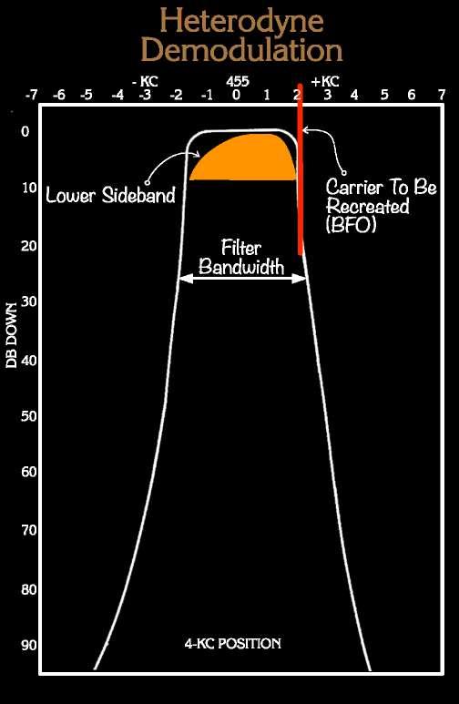
How to Tune the BFO?
A common doubt I had was: how should the BFO be set for proper SSB reception? Referring to the figure shown earlier in the book, the user has more options:
• decide which filter to use: for SSB, I think it should be the 3 or 4 kHz filter, depending on what your receiver has;
• move the received sideband so that it stays exactly in the center of the filter using the tuning control;
• move the re-created carrier with the BFO control so that it stays just above the sideband if you are receiving an LSB transmission, or below it with USB. In the case of a 4 kHz filter, it should stay about at +2 kHz, to exploit a 4 kHz audio bandwidth.
This last point shows that the best BFO position depends on the filter you are using. If you keep the SELECTIVITY control fairly wide, the BFO setting is less important because the sideband can be
The Tuning Knob Allows You to Move The Received Sideband In and Out The Filter Window
The BFO Knob Allows You to Move The Recreated Carrier Along The Filter Window

"moved" within the window filter without much difference. If you change the BFO frequency moderately, you will get a different value for the tuned frequency indicator, but reception will not be affected (again, provided the sideband is completely within the filter band). Using a spectrum analyzer to look at the IF output will help you position the BFO frequency correctly, as we will show practically.
What Selectivity to Use?
Operate your receiver with the narrowest bandwidth filter suitable for your operating mode. A wide bandwidth allows more noise and interference to enter your receiver; on the other hand; a narrower filter provides better signal-to-noise ratio, but may reduce audio quality and require a more accurate BFO setting.
What is the Frequency of an SSB Signal?
What is the frequency of an SSB signal? We can define it as the frequency of the suppressed carrier, if it were present. However, the tuning display shows the value x of the IF filter’s center, so fx, the displayed value, is wrong for an SSB signal. The suppressed carrier would stay at a frequency fy, represented by the red line in the figure. To obtain the value of fy, the signal frequency, we simply correct fx by the BFO frequency (+ for LSB, - for USB). This error can also occur with AM reception, as Collins itself points out in its 51J-4 manual: "…for AM and single-sideband reception using the 3 kc filter the 51J-4 dial reading will not necessarily correspond to the carrier frequency of the station being received. Depending upon whether the upper of lower sideband is tuned, the actual carrier frequency will be approximately 1. 5 kc lower or higher than the dial reading indicates” (see 51J-4 manual, paragraph 3.2.5, page 3.5).
Opinions
It’s interesting to look at the opinions and doubts that people had in the early years of SSB. The following text is excerpted from the US Air Force manual 100-5 “Radio Receivers”, issued on 14 December 1956.
“In a basic single sideband (SSB) system, the RF carrier frequency is amplitude modulated with an audio signal, just like in the ordinary amplitude modulation (AM) system. However, the original carrier frequency is removed by a balanced modulator and one of the sidebands is removed by a filter network. The only radiation from the transmitting antenna is one sideband. This basic system is being
used in some cases, but it has one big disadvantage. In receiving this type of signal, the carrier must be reinserted by the receiver so that there will be a resulting beat frequency, which will produce the original audio frequencies when the signal is detected or demodulated. It has been found that this reinserted carrier frequency must be accurate to within 20 cycles before the resulting audio is intelligible. It is difficult to control a generated frequency in a receiver this accurately, and therefore this system is not widely used. A more common system of SSB is to transmit one of the sidebands and a carrier that has been reduced in amplitude. This carrier must only be strong enough to operate an automatic frequency control circuit in the receiver that will hold the local oscillator within 20 cycles of the original carrier frequency. This system is called a suppressed carrier SSB system.”
Interesting however this note: “There are a number of advantages to SSB. As stated above, two audio signals can be transmitted in the place of one in the AM system, or, when only one sideband is transmitted, the channel required is only half as wide, making it possible to have many more transmitters operating in a certain communications band. Another advantage is that there is about a 9 dB improvement in signal-to-noise ratio. This is possible since a much narrower band is used in handling the same audio frequencies, and the energy required by the full carrier in the AM system is used by the sideband carrying the intelligence. A third advantage that may be possible in conjunction with a teletype system is a reduction in the effect of selective fading. In selective fading, some of the audio frequencies fade as the radiated signal passes through space. In conjunction with radio teletype, two tones may be used for the same purpose so that if selective fading reduces the amplitude of one tone, the other tone will probably be received with full strength. Still another advantage in teletype, when a twin sideband is used, is that six channels of radio teletype can be transmitted on one sideband and a full voice channel can be transmitted on the other sideband.”
Blue Pages General Culture Issues Radioteletype (RTTY)
Wired Teletype
Teletype (TTY) is a method of transmitting text over wires, originally used for point-to-point communications, similar to the classical telegraphy, but more “user friendly”, because it could be used by almost anyone and produced printed text messages, without the need of highly trained operators.
For many years, TTY systems used mechanical teleprinters, like the glorious TG-7 seen in many World War II movies, to convert typed text into electric signals, then transmit them over distances and print out what the correspondent sent.
TTY used the 5-bit Baudot code, which represented the natural evolution of Morse code to make text transmission more easily processed by a machine, with a fixed-length stream of five binary signals called mark (1, i.e., key pressed) and space (0, i.e. key released), each of the same precise duration, plus two control bits (START and STOP). It allowed 32 different characters, which were too few for a practical text. Consequently, two characters (FIGS and LTRS) were used to switch to another set of symbols, making a total of 62 (32 x 2 - 2). Some other symbols were given a special meaning and did not print, such as BELL to make the alarm bell ring (for computer use, however, these symbols were too few and the 8-bit ASCII code was introduced).
The baud rate, i.e. the number of bits per second, was mainly limited by mechanical factors of the teleprinter. The most common speed was 45.45 baud, i.e. 22 ms/bit. With some adjustments, the TG-7 could run at 50 baud. The more modern Teletype ASCII ASR 33 ran at 110 baud, which seemed astronomical to us at the time (Purists will argue that "bit rate" and "baud rate" are not the same thing; often bits/second indicate the effective transferred payload, i.e., in this case excluding the START and STOP bits).
Photo: the TG-7 teleprinter was another great love of my youth; in fact, it was precisely to see it write correctly, something I could not achieve with the unstable BC-312 receiver, that I began to work on the first microprocessors. I can't remember how many times I took it apart and put it back together to fix it; but it was an excellent training ship.

Radioteletype
RTTY (radioteletype) was the method of transmitting TTY signals over radio waves. Two encoding techniques were used: AFSK and FSK.
Audio Frequency Shift Keying (AFSK)
AFSK is the simplest method and uses two audio tones to encode the mark and the space (such as 2125 Hz for mark and 2975 Hz, i.e., with an 850 Hz shift). The tone modulates a carrier in amplitude and, at the destination, two corresponding filters decode the two tones. AFSK does not place any special requirements on receivers and their stability, but it has not been widely adopted for several reasons, mainly related to performance and technical limitations. Because the tones are audio signals, they are more susceptible to phase distortion, frequency drift, and other effects introduced by the audio circuitry or signal path. In addition, AFSK tends to be less bandwidth-efficient than direct FSK, as is intuitive (but we will return to this point).
Frequency Shift Keying (FSK)
Most of the traffic used FSK, where the same frequency shift used for AFSK was generated on the carrier and reconstructed in the receiver by heterodyning a local oscillator (typically the BFO) and using a

A photo from the 1950 manual for the AN/GRC-26 radio set. It seems impossible that they used the BC-342 for RTTY service. Its stability is light years away from what is needed.
In fact, these are the R-336/GRC-26s, i.e., modified BC-342s, with a completely different RF oscillator to reduce frequency drift. RTTY had its requirements.
demodulator with appropriate audio filters to return a zero or a one at the end. This method has advantages, such as avoiding audio-related distortions and produces a cleaner signal that is less prone to errors caused by noise or interference, but it relies on almost absolute stability of the receiver local oscillator and the BFO. I can attest to this: when I had only a BC-312 receiver, I could not receive more than a few lines of text without errors. Due to the increasing frequency congestion in the shortwave bands, an FSK receiver had to be highly precise, accurate, selective, and reliable.
FSK is therefore a frequency modulation, as the name F6 given to it by the International Telecommunication Union (ITU) confirms. Which is the frequency band it occupies? The bandwidth of a Frequency Shift Keying (FSK) signal can be estimated using the Carson's Rule approximation:
B ≅ Δf + 2 × Rb
Where Δf is the shift and Rb the baud rate. For an 850 Hz shift and 45,45 baud, we have a bandwidth of 940 Hz. The same emission in AFSK requires also to send the 2975 Hz tone, so, even forgetting the effect of the data stream, you occupy at least 6 kHz (2975 x 2).
AFSK or FSK?
So, while AFSK had its applications, especially in VHF/UHF bands and systems where FM radios were used, its susceptibility to noise, lower stability, and higher bandwidth usage made it less suitable for high-performance, long-range, or professional HF communications. FSK was superior in terms of reliability, spectral efficiency, and stability, which led to its wider adoption in critical systems like military, maritime, and HF amateur radio communication.

The Baudot code from the TG-7 manual. Note that the
Blue Pages General Culture Issues Mechanical Filters
A Great Improvement
A major improvement in receiver technology, mechanical filters were introduced by Collins Radio Company in the late 1950s. They were designed to increase the selectivity of radio receivers by providing narrow-band filtering with very steep cutoff characteristics, which were also particularly useful for applications such as single sideband (SSB) communications.
What is a Mechanical Filter?
This filter is a mechanically resonant device that receives electrical energy, converts it to mechanical vibration, and then converts the mechanical vibration back to electrical energy at the output.
Mechanical filters consist of three basic elements:
• transducers, which convert electrical vibrations into mechanical vibrations or vice versa;
• metal disks that are mechanically resonant;
• disk coupling rods.
The transducer, which converts electrical to mechanical energy, is a magnetostrictive device based on the principle that certain materials lengthen or shorten in the presence of a magnetic field. Therefore,


Filters

LSB Mechanical Filter


USB Mechanical Filter
CW Crystal Filter
51S-1 Mechanical Filters
when an electrical signal is sent through a coil containing the magnetostrictive material as a core, the electrical oscillation is converted into a mechanical oscillation. The mechanical oscillation can then be used to drive the mechanical elements of the filter. In addition to the electrical and mechanical conversion, the transducer also provides proper termination for the mechanical network.
The electrical equivalent circuit shows that the center frequency of the mechanical filter is determined by the metal disks, which are represented by a series resonant circuit, L1 C1. Since each disk represents a series resonant circuit, increasing the number of disks increases the skirt selectivity of the filter.
In the equivalent circuit, the coupling capacitors, C2, represent the rods that couple the disks. By varying the mechanical coupling between the disks, i.e., making the coupling rods larger or smaller, the bandwidth of the filter is varied. Since the bandwidth varies approximately as the total area of the coupling wires, the bandwidth can be increased by either using larger or more coupling rods.
Mechanical filters revolutionized radio communication systems at the time by providing much better performance in terms of frequency selectivity compared to traditional LC (inductor-capacitor) filters. They became widely used in high-end amateur radio transceivers and military communication equipment throughout the 1960s and 1970s.

I read that the filters were "fine-tuned" using dental drills to remove portions of the disks (outer edge increased frequency, center decreased frequency) until the series of disks resonated to create the filter, and that this operation was done mostly by women during the war, but it seems to be a fake news, because they were introduced after the war.


Blue Pages General Culture Issues Sensitivity
Vexata Quaestio
Vexata Quaestio is a Latin expression typically used for theological disputes among irreconcilable theses. In more modern contexts, I could say that sometimes the sensitivity issue is another of those minefields where experts can write tons of formulas which I no longer understand. Here I have limited myself to gathering a distillation of consolidated answers to the most common doubts (especially mine).
How is Sensitivity Defined?
According to Wikipedia, sensitivity is the minimum amount of input signal required to produce a specified output signal with a specified signal-to-noise ratio. More generally, it is the signal level required for meaningful received information. It is common to express sensitivity in µV to obtain a signalto-noise ratio of 10 dB (in power) and thus 10:1.
How Important Is it?
One might think that the sensitivity, i.e., their Signal to Noise ratio (“(S+N)/N or “S/N”) of the receivers is not as fundamental anymore, because in today's world the level of electromagnetic pollution is so high that it happens that the input stages of the receivers can become clogged by noise levels greater than the sensitivity of the receiver. Some have even theorized about this, as Telefunken did when it introduced its E863 receiver, which we will describe in this book. But we are working for the pleasure of restoring these ancient masterpieces, so we want to make them as perfect as possible. We will return to this fascinating subject in the course of the discussion of others of the receivers presented in this book.

Sensitivity Measurement
How do we measure sensitivity? It is simple in theory, but as we will see, there are many things you need to know to get meaningful results.
You need to be able to generate calibrated signals and read the output power. So you need:
• a modulated signal generator with a calibrated output, even with small signals, and 50 Ω output impedance (like, for example, the HP 8640B here on the left);
• an output level meter. I often use the wonderful TS-585D/U you see in the photo on the next page, but the receiver’s line output meter, when present, can often be used as well.
Procedure for Measurement
In short, the procedure is:
• connect the generator to the receiver antenna input, but keep its output level at zero;
• without a signal and with only the noise, set the output meter to a certain value (e.g. -10 dBm);
• increase the amplitude modulated signal until you read +10 dB (0 dBm in the example).
The generator output level is the receiver sensitivity value.
Measurement Units
Sensitivity can be expressed in RMS microvolts, dBm, or dBµV. If you know the input impedance of your receiver, you can quickly convert one unit to another using tables or calculators available on the Internet.
Impedance Matching
To make a correct measurement, you must pay attention to impedance matching, both for the receiver's output and input. An impedance mismatch will lead to incorrect measurements, and I think this kind of error can explain why you can read very different sensitivity values from different people.
Photo: the TS-585/U is an interesting passive instrument which measures audio output power, up to 5 W, in milliwatt (mW) or decibel (dB). It can also measure the output impedance of an amplifier, or, better, it can find the impedance that best matches it, among the possible 38 that it can use. Note the magnificent switch of the impedance transformer. This is the D version. The first produced (the “A” version) was completely different, being "vertical" instead of "rectangular."
The output measurement is a ratio, so within certain limits a possible impedance mismatch error has little effect. The situation is different at the input, where we want to read an absolute value. Perfect impedance matching is therefore required between the signal generator and the antenna input of the receiver.
Ambient Noise
Another area of concern is ambient noise. It is rather intuitive that a strong noise will completely change the measurements you make when you are dealing with small signals.
Basically, noise can enter your measurement setup in two ways: conducted or radiated. Conducted noise is the type that travels with the signals through power lines or other wires. Radiated noise is noise that travels through space and arrives as unwanted electromagnetic waves.
In my case, I am not entirely sure of the path it chose, but I was able to find and eliminate two strong sources of noise:
• a WiFi range extender, the kind that goes through the house wiring;
• an old 2008 MacPro that produced a lot of noise even when it was apparently turned off.
Both produced wideband noise, but the first also produced a "moving" carrier that crossed the spectrum quite quickly, causing a periodic "tic" in the receiver's speaker (incidentally, I fell for this again recently, thinking of a fault in the Siemens Pag 148 panoramic adapter described in this book).
Another source of noise is... the radio spectrum itself. At least for me, it is better to work during the day, when the propagation is shorter. In conclusion, try to eliminate any source of noise you have before trying to make adjustments.
Obviously, the noise should not enter, above all, from the generator/receiver link. Use a good and short cable, with the proper connections. Some suggest using ferrite toroids on both ends; it seems like a good suggestion.
Measurement Units
There are probably many ways to express the sensitivity value and the strength of a signal in general. Among the most common are
• voltage linear, normally microvolts or millivolts;
• power logarithmic, normally specified in dBm (decibel-milliwatts), unit of power level expressed
using a logarithmic decibel (dB) scale relative to one milliwatt (mW). It can express both very large and very small values in a short form. Don’t confuse it with the decibel (dB), a dimensionless unit, used for quantifying the ratio between two values, such as our signal-to-noise ratio.
• voltage logarithmic, dB µV. Conceptually similar to the dBm, it is the absolute level unit relative to 1 µV (microvolt). It was widely used by Collins in their meter instruments, like the 51J, the R-390, the R-390A and the 51S-1;
• the S-scale, used by radio amateurs.
Note that we can convert from one scale to the other, but for dBms we need to use Ohm's law, and therefore we need to know the input impedance.
I have prepared a conversion table from dBµV, dBm (50 Ω), dBm (125 Ω) and µV. I also added the corresponding S-meter values but I could not find a secure conversion logic, so take it with a grain of salt.
Sartorello's Method
My friend Francesco uses a different method for measuring sensitivity, which is, less scientific but very practical. He defines the sensitivity as the level at which the "beep" of the modulated signal is still audible. At first I was skeptical, but then I discovered that this method gives a value about 10 dBm lower than the real one. We could name it MAS, for Minimum Audible Signal.
If you are not interested in extreme accuracy, this method is incredibly fast and allows you to quickly check all the bands in a reasonable amount of time to see if any of them are not working well. I found one defective band in this way, and only then I went to the more accurate method.
