Introduction to Electronic Filters
Learn RC and RL Filters with Hands-On Circuits and Simulation
Academy Pro Title by Peter Dalmaris, PhD
Learn RC and RL Filters with Hands-On Circuits and Simulation
Academy Pro Title by Peter Dalmaris, PhD
Learn RC and RL Filters with Hands-On Circuits and Simulation
● Dr Peter Dalmaris
● This is an Elektor Publication. Elektor is the media brand of Elektor International Media B.V. PO Box 11, NL-6114-ZG Susteren, The Netherlands Phone: +31 46 4389444
● All rights reserved. No part of this book may be reproduced in any material form, including photocopying, or storing in any medium by electronic means and whether or not transiently or incidentally to some other use of this publication, without the written permission of the copyright holder except in accordance with the provisions of the Copyright Designs and Patents Act 1988 or under the terms of a licence issued by the Copyright Licencing Agency Ltd., 90 Tottenham Court Road, London, England W1P 9HE. Applications for the copyright holder's permission to reproduce any part of the publication should be addressed to the publishers.
● Declaration
The material in this publication is of the nature of general comment only, and does not represent professional advice. It is not intended to provide specific guidance for particular circumstances and it should not be relied on as the basis for any decision to take action or not take action on any matter which it covers. Readers should obtain professional advice where appropriate, before making any such decision. To the maximum extent permitted by law, the author and publisher disclaim all responsibility and liability to any person, arising directly or indirectly from any person taking or not taking action based on the information in this publication.
● ISBN 978-3-89576-698-5 Print
ISBN 978-3-89576-699-2 eBook
● © Copyright 2025 Elektor International Media www.elektor.com
Editor: Clemens Valens
Prepress Production: D-Vision, Julian van den Berg
Printers: Ipskamp, Enschede, The Netherlands
Elektor is the world's leading source of essential technical information and electronics products for pro engineers, electronics designers, and the companies seeking to engage them. Each day, our international team develops and delivers high-quality content - via a variety of media channels (including magazines, video, digital media, and social media) in several languages - relating to electronics design and DIY electronics. www.elektormagazine.com
5.1
5.3 Activity 1: Time constant experiment ................................
5.4 Impact of time constant on signal shape .............................
5.5 Activity 2: Impact of the Time Constant on Signal Shape
5.6 Audio tone shaping ............................................
5.7 Activity 3: Hear the effect of filtering ................................
5.8 Sensor signal conditioning .......................................
5.9 Activity 4: A noisy light sensor with a filter
5.10 Noise filtering
5.11 Activity 5: Remove mains humming noise
5.12 Debouncing switches
5.13 Activity 6: Button debouncing on the breadboard ......................
5.14 Analog smoothing of digital PWM signals ............................
5.15 Activity 7: Smoothing of a PWM signal ..............................
5.16 Power supply filtering ..........................................
5.17 Activity 8: Design a filter for a microphone ...........................
5.18 Activity 9: Design a filter for a thermistor or photoresistor ................
6.1
6.2 Cascading RC
6.3 Activity 1: Cadcading RC filters on the breadboard
6.4 Band-pass filter ...............................................
6.5 Activity 2: Band-pass filter on the breadboard .........................
6.6 Filter design constraints: loading, attenuation, bandwidth
6.7 Activity 3: Design a two-stage filter to isolate a frequency band
6.8 Activity 4: Simulate cascaded filters with varying cutoff frequencies
7.1
7.3 Python fundamentals for electronics
7.4 Essential NumPy for electronics ....................................
7.5 Visualisation with Matplotlib
7.6 Understanding and modifying electronics
7.7 Additional
8.4 Manipulating fractions
8.5 Powers and roots
8.6 Complex numbers
8.7 Frequency, angular frequency, and substitution
8.8 Quick guide to simplifying transfer functions ...........................
8.9 Formula map.................................................
The idea for this book emerged from a simple observation: students often understand basic electronic components well but struggle when asked to apply that knowledge to real-world signal control problems. Filters, though conceptually straightforward, frequently appear abstract or unnecessarily complicated when introduced solely through mathematical formalisms. Yet, filters are everywhere, quietly performing critical functions in audio equipment, communication devices, industrial sensors, and embedded systems. I wrote this book to address this gap. My goal is to teach first-order filters in a way that is both rigorous and approachable, blending theory with hands-on practice. Rather than treating first-order filters as a brief stepping stone towards more complex subjects, this book treats them as powerful tools that deserve careful attention in their own right. Throughout this book, you will find a continuous emphasis on practice. You will use Python scripts to simulate circuits, online simulators to quickly prototype designs, and realworld breadboard experiments to observe circuit behaviour with oscilloscopes and spectrum analysers. This combination of simulation and physical experimentation is intended to make the material tangible and memorable. It is through building, observing, and analysing that theory becomes truly internalised.
This book assumes that you are already familiar with the fundamentals of electronics, particularly the behaviour of resistors, capacitors, and inductors, as well as basic circuit analysis techniques. If you have completed the Introduction to Electronics course or possess similar knowledge, you are fully prepared to embark on the journey ahead. Learning about filters is not only about gaining technical skills. It is also about learning to think critically about signals, noise, and system behaviour. It is about recognising the subtle but vital roles that small circuits play in the reliability and performance of much larger systems. My hope is that, by the end of this book, you will not only know how to design and analyse first-order filters, but also appreciate their elegance and importance in the broader context of electronics. I encourage you to approach the material with curiosity and patience. Build the circuits, run the simulations, question the results, and take the time to explore the behaviour of filters beyond the examples provided. The deeper your engagement with the material, the stronger and more intuitive your understanding will become. Welcome to the study of first-order filters. I am excited to be your guide on this practical and rewarding journey.
This book is designed to be both a study guide and a practical reference. To gain the maximum benefit from the material, it is important to approach it as an active participant rather than a passive reader. Each chapter builds systematically on the knowledge and skills introduced earlier. Concepts are introduced progressively, beginning with a general understanding of filters and their classifications, and moving towards detailed analyses and practical experiments with first-order filter circuits. It is recommended that you read the chapters sequentially, as each topic prepares the foundation for the next. Wherever simulations are presented, you are encouraged to run the provided Python scripts on your own system. These simulations allow you to visualise filter behaviours that are difficult to grasp from static text alone. The scripts are designed to be clear and accessible, even for readers with only basic Python programming experience. Modifying the parameters and
observing how the results change is an excellent way to deepen your understanding. You will find all Python scripts on Github at https://github.com/futureshocked/introduction_to_ electronics_filters
In addition to Python simulations, many examples reference online circuit simulators. These simulators allow you to experiment with filter circuits interactively. It is highly recommended that you reproduce these circuits yourself, adjust component values, and observe how these changes affect circuit behaviour. This hands-on exploration will reinforce the theoretical principles discussed in the text.
Real-world experiments form another vital component of the learning experience. When possible, you should construct the simple filter circuits described in the book on a breadboard. Using basic laboratory instruments such as oscilloscopes and spectrum analysers, you will be able to observe signal behaviour directly. These experiments are chosen to be accessible with modest equipment, yet they provide invaluable experience in measurement and analysis. As you work through the material, it is important to keep a notebook or digital journal of your observations, measurements, and conclusions. Reflecting on what you observe, especially when simulation results differ from physical measurements, will build a deeper and more critical understanding of electronic behaviour.
Finally, although this book focuses specifically on first-order filters, you will occasionally encounter references to second-order filters and more advanced topics. These references are included to provide context and to prepare you for future learning. However, it is not necessary to understand higher-order filters in detail before mastering the first-order designs presented here. Your success with this book depends less on speed and more on deliberate practice. Take the time to build, test, and truly understand each circuit. By doing so, you will develop both the theoretical knowledge and the practical confidence that define an effective electronics practitioner.
If you have found an error, please let me know. Go to https://connect.techexplorations. com/bugs/introduction-to-electronics, and fill in the form. I'll get it fixed and update the book.
This book offers a practical and structured exploration of first-order filters, intended for readers who have completed the Introduction to Electronics course or possess equivalent foundational knowledge. It is designed for students, hobbyists, and professionals who wish to build a working understanding of filter circuits, both in theory and in practice.
The primary focus of this book is to bridge theoretical knowledge with practical skills. Readers will not only learn the fundamental concepts underlying first-order filters, but also how to apply these concepts through circuit simulations and hands-on experiments. The approach taken throughout the text emphasises understanding through doing. Theory is introduced progressively and supported by meaningful applications.
One of the core methods employed in this book involves the use of Python scripts. These scripts are provided to simulate various filter behaviours, allowing the reader to visualise the effect of circuit parameters on the performance of first-order filters. Python, with its powerful numerical and graphical libraries, offers an accessible and flexible environment for rapid experimentation and deep analysis. The simulations presented throughout the chapters are simple enough to run on any modern computer yet sophisticated enough to yield meaningful insights.
Alongside Python-based simulations, the book makes extensive use of online circuit simulators. These web-based tools allow readers to design, modify, and test filter circuits without the need for physical components. Using an online simulator, it is possible to quickly iterate through different configurations, examine time-domain and frequencydomain behaviours, and understand the impact of design decisions. Online simulators provide an invaluable platform for bridging the gap between theoretical design and practical implementation.
While simulation is a powerful educational tool, nothing replaces the tactile experience of building real circuits. For this reason, this book also guides readers through practical experiments on a breadboard. These experiments involve assembling basic first-order filter circuits using resistors, capacitors, and inductors, and observing their behaviour using laboratory instruments such as oscilloscopes and spectrum analysers. By directly measuring input and output signals, readers will gain an intuitive and technical understanding of key filter characteristics, such as cutoff frequency, phase shift, and roll-off.
Throughout the book, emphasis is placed on the connection between simulation and measurement. Readers are encouraged to compare simulated results with real-world measurements, to analyse any discrepancies, and to understand the reasons behind them. This process of continuous verification not only reinforces learning but also builds critical engineering habits.
The study of first-order filters in this book is not presented as a mere preliminary step towards higher-order filters. Instead, first-order filters are treated as valuable and powerful
tools in their own right. Many practical applications rely solely on first-order designs due to their simplicity, reliability, and efficiency. Readers will encounter numerous examples drawn from real-world electronics, including audio processing, sensor interfacing, power management, and communication systems.
By the end of the book, readers will have acquired a robust understanding of first-order filters. They will be able to design, simulate, build, and measure the performance of basic filter circuits with confidence. They will also be well-prepared for more advanced studies in second-order filters, active filter design, and digital signal processing, should they choose to pursue them.
This book is structured in a progressive manner, beginning with an introduction to filters and their applications, proceeding to an in-depth exploration of first-order low-pass, highpass, band-pass, and band-stop filters, and concluding with practical projects and case studies. Each chapter builds systematically on the previous one, ensuring that knowledge and skills are developed logically and thoroughly.
The objective of this book is to make the study of first-order filters accessible, practical, and engaging. Through a combination of theory, simulation, and hands-on experimentation, readers will achieve a deep and enduring understanding of this essential topic in electronics.
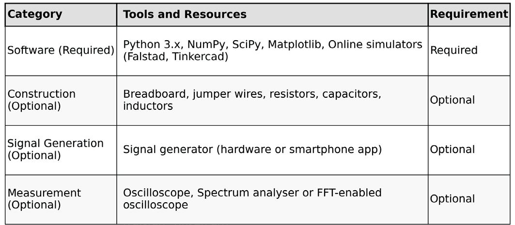
This book is designed to be practical and accessible. To gain the full educational benefit, you will need access to a small set of software tools, and optionally, basic hardware tools.
While building physical circuits can greatly enhance your understanding, it is entirely possible to complete all simulations, exercises, and projects in this book using only Python and a circuit simulation platform.
In this chapter, we review the software and hardware tools recommended for following the activities described throughout the book.
Software tools are central to the learning approach used in this book. Simulations allow you to visualise the behaviour of filters, to explore how component values affect circuit performance, and to verify theoretical predictions with practical examples. Python environment Python is used throughout the book to simulate the behaviour of first-order filters and to generate Visualisations such as time-domain plots and frequency responses.
The following software components are required:
- Python 3.x: A current version of Python is recommended (version 3.8 or newer).
- NumPy: A library for numerical operations and array handling.
- SciPy: A library that provides scientific computing tools, including signal processing functions.
- Matplotlib: A plotting library used to visualise signals and filter responses. Python can be installed directly from the official Python website, or via distributions such as Anaconda, which include all required libraries pre-installed. If necessary, libraries can be installed individually using pip.
All Python scripts presented in this book are provided with clear explanations and can be modified easily to explore different circuit parameters and signal conditions.
Online circuit simulators An online circuit simulator is the second essential tool. It enables you to construct and test filter circuits graphically, without requiring any physical components.
Recommended simulators include:
- CircuitLab: (http://circuitlab.com/):
Provides an intuitive, real-time Visualisation of voltage and current behaviours.
- Tinkercad Circuits (https://www.tinkercad.com/circuits): A comprehensive web platform that supports circuit simulation as well as Arduino integration, suitable for readers interested in embedded applications.
Using Python and an online circuit simulator, you can complete every simulation, exploration, and design exercise described in this book.
Hardware Tools (Optional)
While not required, having access to basic laboratory equipment can deepen your understanding of filter behaviour by allowing you to build real circuits and measure their performance directly. Readers who have access to these tools are encouraged to use them, but they are not necessary to complete the learning objectives of this book. The following hardware tools are considered optional:
Breadboard and components
A standard breadboard along with jumper wires, resistors (ranging from 100 Ω to 100��Ω), capacitors (from 10 nF to 10 ��F), and inductors (from 10 ��H to 10 mH) would allow you to physically build the filters studied in the book.
Analog Discovery 3 Analysis Tool I use the Analog Discovery 3 analysis tool, which combines oscilloscope, spectrum analyser, signal generator, and power supply capabilities in one compact device. You can use this or any similar multifunction equipment to perform the hands-on experiments described.
Signal Generator
A basic signal generator can provide the input signals required to test your filter circuits. In the absence of a dedicated signal generator, software applications for smartphones or computers can serve as an alternative.
Oscilloscope
An oscilloscope enables the measurement of the time-domain behaviour of input and output signals.
A simple two-channel digital oscilloscope with a bandwidth of at least 20 MHz is sufficient for the types of filters and signals discussed.
Spectrum analyser
A spectrum analyser, or an oscilloscope with an FFT mode, can be used to observe how filters attenuate or pass different frequency components.
This tool provides a frequency-domain view, complementing time-domain observations.
Although valuable for hands-on understanding, all experiments and filter characterisations in this book can be conducted fully using simulation environments.
The presence of physical hardware is therefore optional and not a barrier to successful completion of the material.
Throughout this book, all essential experiments and observations are demonstrated using Python simulations and online circuit simulators. These platforms allow you to build a complete understanding of first-order filter theory and practice without the need for additional equipment. However, if you have access to the recommended optional tools, you are encouraged to replicate experiments physically.
Hands-on construction and measurement deepen intuition and expose you to real-world phenomena such as component tolerances and parasitic effects, which cannot be fully captured in simulations. Regardless of your available tools, this book is structured to ensure that you can achieve all of its learning objectives and complete all exercises using freely available software resources.
2.1 Introduction to filters
Filters are essential building blocks in the design and analysis of electronic circuits. They allow engineers and hobbyists to control which signals pass through a system and which signals are attenuated or blocked. At their core, filters shape the flow of electrical energy, enabling the separation, enhancement, or suppression of different parts of a signal.
Filters are used across countless applications. In audio systems, filters can remove unwanted noise or adjust the tonal quality of sound. In communication systems, they are vital for selecting specific frequency bands. In power electronics, filters suppress voltage spikes and reduce electromagnetic interference. Filters are critical components of virtually all non-trivial electronic systems, and this is why a solid understanding of their behaviour is so important.
Filter applications
To give you a sense of the wide application of filters in all sorts of gadgets, I have constructed the table below (see next page).
Chapter 2 • What is a filter?
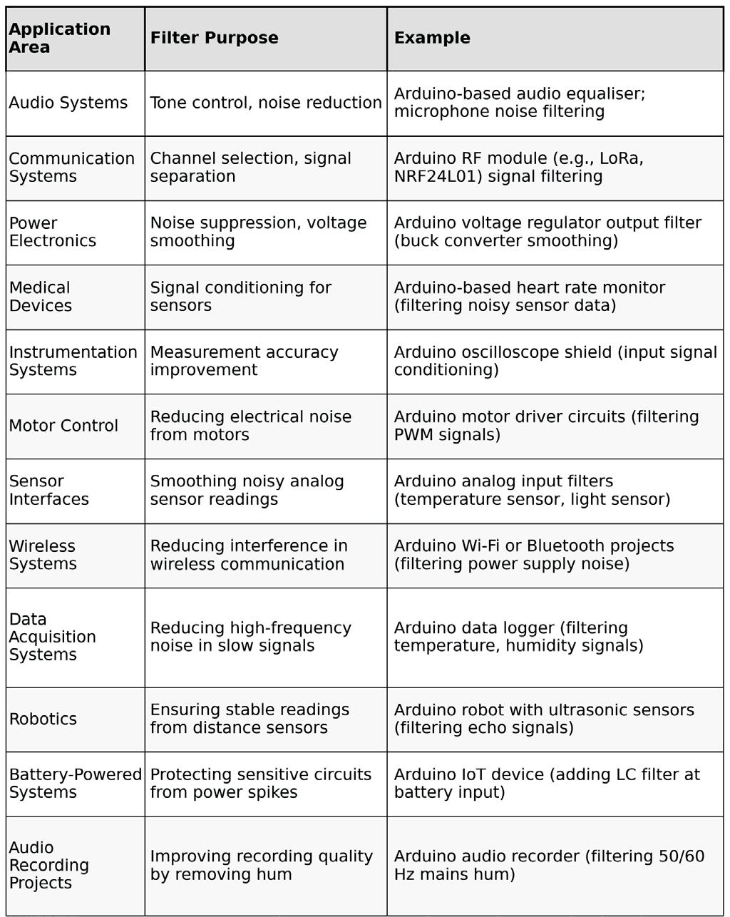
Figure 2.1: Example applications of filters
In the broadest sense, filters can be classified into two main categories:
• Analog filters operate directly on continuous-time signals using resistors, capacitors, inductors, and active components like operational amplifiers.
Chapter 2 • What is a filter?
• Digital filters work on discrete-time signals, manipulating digitized data using algorithms implemented in software or digital circuits.
Further classification is based on frequency behaviour:
• Low-pass filters allow low-frequency signals to pass while attenuating highfrequency signals.
• High-pass filters allow high-frequency signals to pass while attenuating lowfrequency signals.
• Band-pass filters allow a specific range of frequencies to pass while attenuating frequencies outside this range.
• Band-stop filters attenuate a specific range of frequencies while allowing others to pass.
The fundamental components used to build analog filters are familiar to you from the "Introduction to Electronics" course:
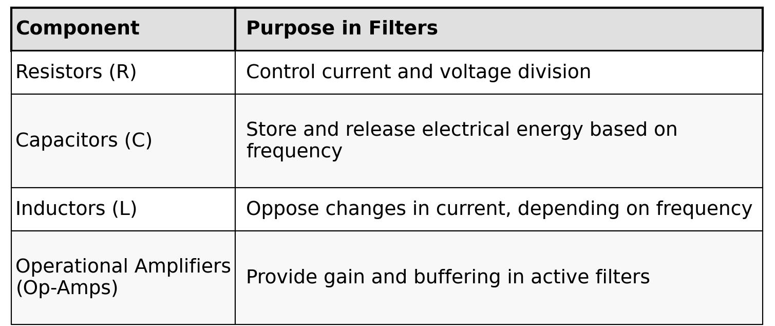
Figure 2.2: Components used in first and second order filters
First-order filters typically use one reactive component (either a capacitor or an inductor) and one resistor. These simple circuits introduce a frequency-dependent behaviour that creates a gradual transition between passband and stopband.
Second-order filters introduce a second reactive component. This addition allows for steeper transitions and more selective frequency control. For example, a second-order lowpass filter might use two capacitors and two resistors, or one inductor and one capacitor combined with resistors.
Later in the book, you will see examples of how specific combinations of these components create different types of first-order filters.
Knowledge prerequisites
If you completed my course "Introduction to Electronics", you already have a strong foundation for understanding how filters work:
• You know how resistors, capacitors, and inductors behave individually in a circuit.
• You are familiar with concepts such as voltage division, time constants, and impedance.
• You have seen how capacitors block DC signals and pass AC signals, while inductors do the opposite.
• You have used Ohm's Law, Kirchhoff's Laws, and basic circuit analysis techniques to solve practical problems.
First-order filters naturally extend these ideas. For instance:
• A simple RC low-pass filter is just a resistor and a capacitor arranged to favour low-frequency signals.
• A RL high-pass filter is a resistor and an inductor arranged to favour highfrequency signals.
Second-order filters build upon this even further, requiring you to combine what you know about how capacitors and inductors behave when they interact together in more complex networks.
Throughout this book, you will see how familiar principles are applied in new ways to design and analyse filters, and you will acquire the additional mathematical tools needed to work with more advanced concepts.
Why focus on first-order filters?
This book focuses specifically on first-order analog filters because they are the most accessible and versatile type of filter:
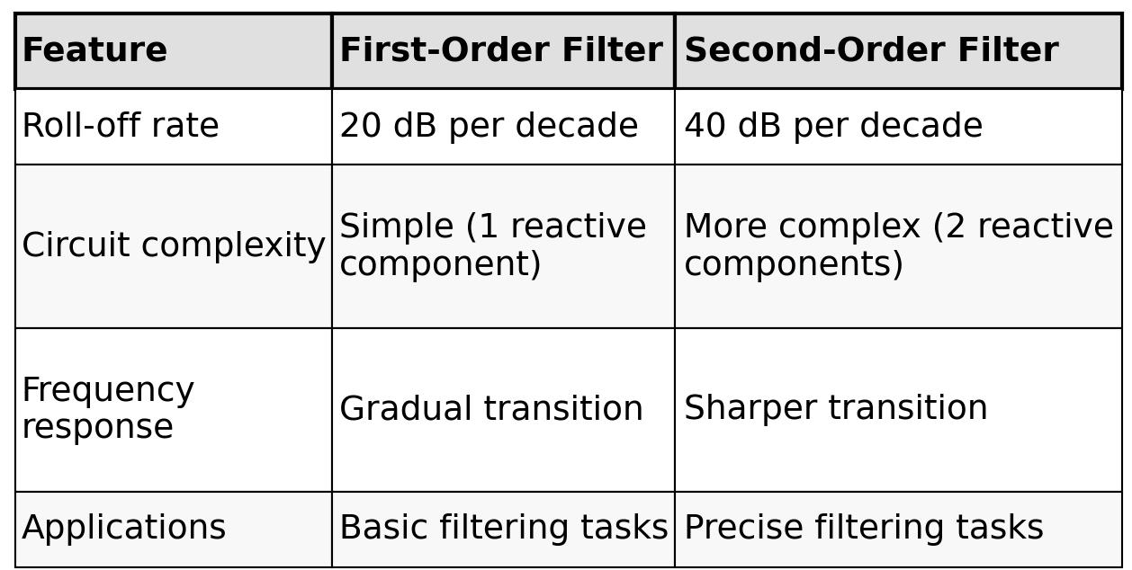
Figure 2.3: Main attributes of first and second order filters
First-order filters are easy to design, analyse, and implement. They provide a solid entry point into the world of signal filtering without requiring complex mathematics from the start.
As you move through this book, you will learn the necessary mathematics and design techniques needed to create your own first-order filters confidently. The step-by-step approach ensures that every new concept builds naturally on what you already know.
First-order and second-order filters are far more than academic exercises. They are essential tools in modern electronics, shaping signals, protecting circuits, and enabling communication, control, and precision. By mastering first-order filters, you gain practical skills that are directly useful across a wide range of real-world applications. The concepts you are about to learn will not only help you in designing circuits, but also deepen your understanding of how everyday technologies around you operate.
First-order filters, despite their simplicity, are used everywhere because of their efficiency, low cost, and reliability. In many cases, a first-order filter is the best solution: it performs the needed function with minimum components, low power consumption, and minimal design complexity.
Here are some key reasons why learning first-order filters is well worth your effort:
- Real-world relevance: Many practical circuits use first-order filters as-is, without modification.
- Foundational knowledge: Understanding first-order behaviour is essential even when designing more complex, higher-order systems.
- Efficient solutions: When size, power, and cost matter (which they almost always do), first-order filters are often preferred.
Second-order filters certainly have important applications, particularly when more precise or steeper filtering is needed. However, they build on the same ideas you are about to master in studying first-order filters.
Real-world applications of first- and second-order filters
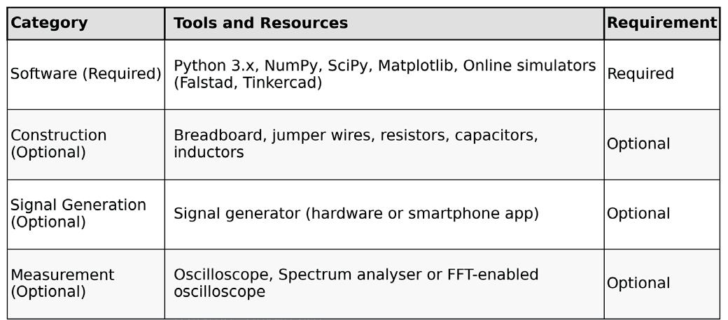
Figure 2.4: Some real-world applications of first- and second-order filters
Here's some everyday applications for these filters:
Audio applications:
When you adjust the bass or treble controls on a music player, simple first-order filters are shaping the sound. Capacitors and resistors modify the balance of low and high frequencies to match your preference.
Sensor inputs:
An Arduino reading a temperature sensor can receive noisy signals due to environmental interference. A small RC low-pass filter, using just a resistor and a capacitor, can significantly improve the quality of the sensor reading.
Motor control:
When controlling a motor's speed with PWM (Pulse Width Modulation), a first-order lowpass filter can smooth the voltage and prevent the motor from producing audible whining noises.
Wireless systems:
Before transmitting or receiving wireless signals, circuits often include filters to ensure that only the desired frequencies are used. First-order filters can remove simple spurious signals, while second-order filters are sometimes used for tighter frequency control.
While first-order filters are sufficient for many tasks, second-order filters are valuable when:
• A sharper transition between passed and blocked frequencies is required.
• Higher selectivity is needed, such as isolating a very narrow frequency band in communication systems.
• Improved stability and control over gain and phase are critical, such as in feedback control systems.
Learning second-order filters becomes natural and much easier once you are confident with the concepts and behaviours of first-order filters.
2.3 The four filters: low-pass, high-pass, band-pass, band-stop
In the study of electronic filters, four fundamental types of filters are commonly encountered. Each type plays a specific role in controlling how signals of different frequencies are treated by a circuit. Understanding these filters will give you the ability to design circuits that emphasise or suppress signals based on their frequency content.
In this chapter, we will look closely at each of these four filter types, explain what they do, and discuss how they can be realised using first-order or second-order circuits.
A low-pass filter allows signals with frequencies below a certain cutoff frequency to pass through with little attenuation, while it attenuates signals with frequencies above the cutoff.
In other words, low-pass filters "pass the lows" and "block the highs."
Everyday Example:
In an audio system, a low-pass filter can be used to send only low-frequency signals to a subwoofer, removing unwanted higher-frequency sounds.
First-Order Implementation:
A first-order low-pass filter can be built using a resistor and a capacitor (RC circuit) or a resistor and an inductor (RL circuit). The roll-off beyond the cutoff frequency is gentle, at a rate of 20 dB per decade.
Second-Order Implementation:
A second-order low-pass filter uses two reactive components (e.g., two capacitors, or one capacitor and one inductor). The roll-off is steeper, at 40 dB per decade, providing better separation between passed and blocked frequencies.
A high-pass filter does the opposite of a low-pass filter. It allows signals with frequencies above a certain cutoff frequency to pass through, while it attenuates signals with frequencies below the cutoff.
Everyday Example:
In audio systems, a high-pass filter can be used to remove deep, low-frequency rumble from a recording, preserving only the midrange and treble sounds.
First-Order Implementation:
A first-order high-pass filter can be constructed using a capacitor and a resistor (RC circuit) or an inductor and a resistor (RL circuit), but arranged differently from the low-pass configuration. The filter begins attenuating signals below the cutoff frequency at a rate of 20 dB per decade.
Second-Order Implementation:
A second-order high-pass filter uses two reactive components and achieves a steeper attenuation of 40 dB per decade.
Band-Pass Filters
A band-pass filter allows signals within a specific range of frequencies (a "band") to pass through while attenuating signals at frequencies lower or higher than this band. Band-pass filters are crucial when only a specific range of frequencies is needed.
Everyday Example:
In radio receivers, a band-pass filter selects the desired broadcast frequency while rejecting others.
First-Order Implementation:
A first-order band-pass filter can be made by cascading a first-order low-pass filter with a first-order high-pass filter. However, the frequency selection is not very sharp. The filter's bandwidth is relatively wide, and its ability to isolate a narrow frequency band is limited.
Second-Order Implementation:
A second-order band-pass filter offers much sharper selection, isolating a narrow band of frequencies with a steeper roll-off on both sides of the band. This is necessary when precise frequency targeting is required, such as in communication systems.
Band-Stop Filters
A band-stop filter (also called a notch filter) does the reverse of a band-pass filter. It attenuates signals within a certain range of frequencies while allowing signals outside this range to pass through.
Everyday Example:
In audio systems, a band-stop filter can be used to eliminate a specific unwanted frequency, such as the 50 Hz or 60 Hz hum from electrical mains interference.
First-Order Implementation:
A first-order band-stop filter can be made by combining a low-pass filter and a high-pass filter in parallel. Like the first-order band-pass filter, it offers only gentle attenuation and a wide transition band.
Chapter 2 • What is a filter?
Second-Order Implementation:
A second-order band-stop filter provides a much sharper notch, attenuating a narrow range of frequencies much more effectively. This is ideal when targeting a specific, problematic frequency for removal.
Which filters can be first-order?
These plots depict the frequency response for the four types of filters:
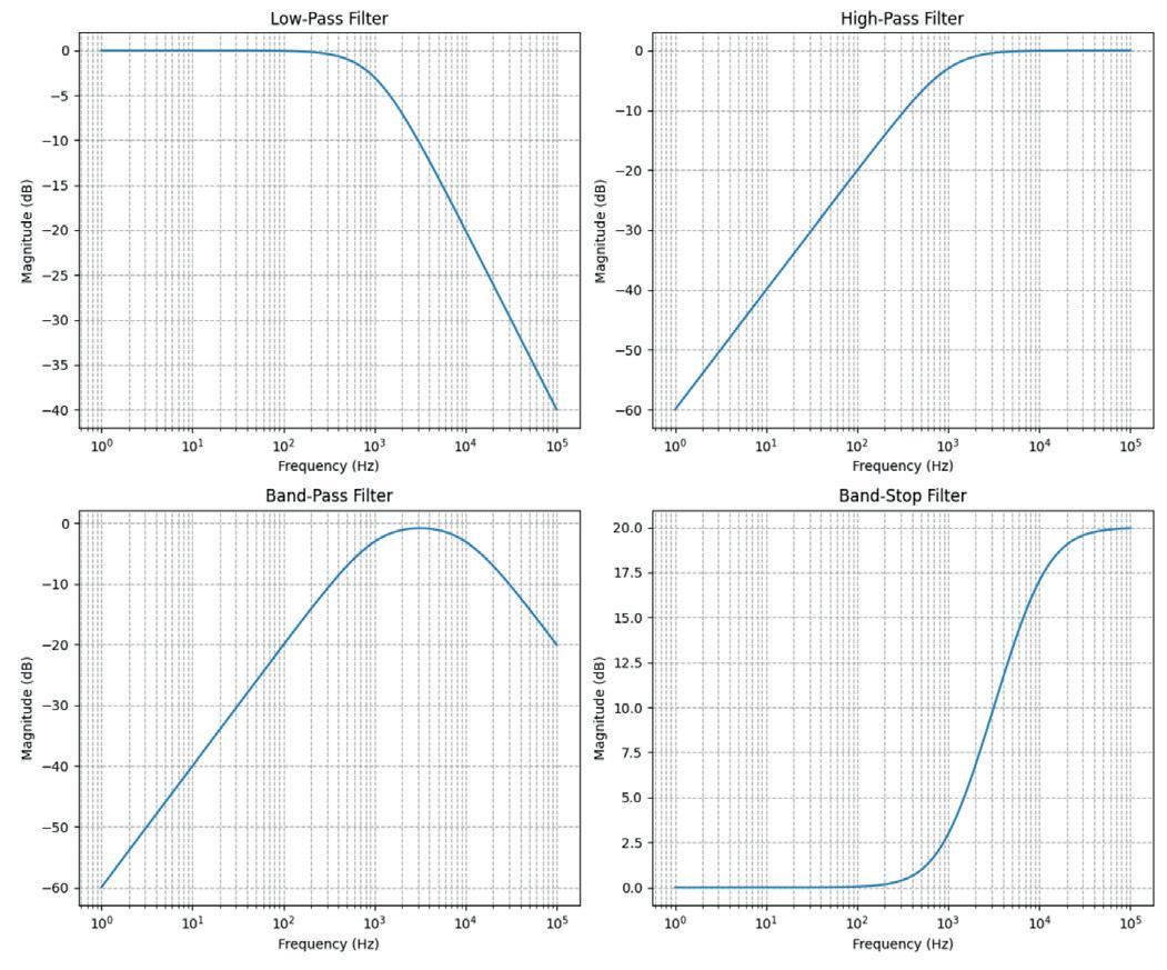
Figure 2.5: The frequency response for the four types of filters
And, this table summarises which of these filters can be implemented with a first or second order circuit:
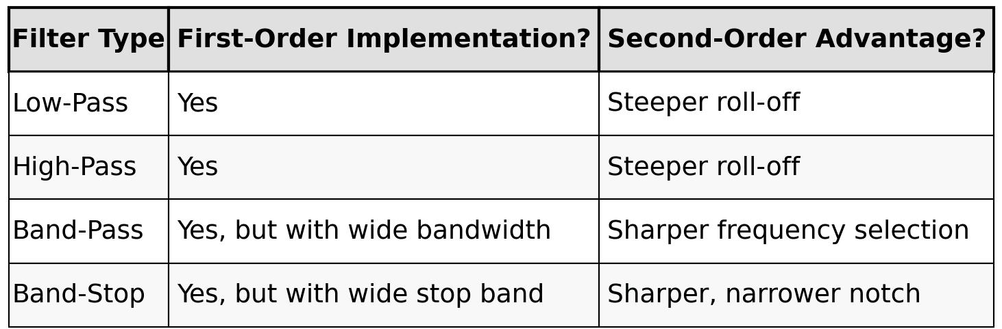
Figure 2.6: Filter type and implementation
• Low-pass and high-pass filters are very effective even as first-order filters, especially when gentle filtering is acceptable or desired.
• Band-pass and band-stop filters can be implemented using first-order techniques but perform much better when built as second-order circuits, especially when narrow frequency control is important.
If you'd like to experiment with the plots, feel free to play with this Python script:
import numpy as np
import matplotlib.pyplot as plt
def plot_filters():
# Frequency range (logarithmic)
freq = np.logspace(0, 5, 500) # 1 Hz to 100 kHz
# Define cutoff frequencies
f_low_cutoff = 1000 # 1 kHz
f_high_cutoff = 10000 # 10 kHz
# Angular frequencies
omega = 2 * np.pi * freq
omega_low = 2 * np.pi * f_low_cutoff
omega_high = 2 * np.pi * f_high_cutoff
# First-order transfer functions (magnitude)
low_pass = 1 / np.sqrt(1 + (freq / f_low_cutoff)**2)
high_pass = (freq / f_low_cutoff) / \ np.sqrt(1 + (freq / f_low_cutoff)**2)
# Band-pass and Band-stop approximations
band_pass = (freq / f_low_cutoff) / \
np.sqrt((1 + (freq / f_low_cutoff)**2) * (1 + (freq / f_high_cutoff)**2))
band_stop = np.sqrt((1 + (freq / f_low_cutoff)**2) / (1 + (freq / f_high_cutoff)**2))
# Create plots
fig, axs = plt.subplots(2, 2, figsize=(12, 10))
axs[0, 0].semilogx(freq, 20*np.log10(low_pass))
axs[0, 0].set_title('Low-Pass Filter')
axs[0, 0].set_xlabel('Frequency (Hz)')
axs[0, 0].set_ylabel('Magnitude (dB)')
axs[0, 0].grid(True, which='both', ls='--')
axs[0, 1].semilogx(freq, 20*np.log10(high_pass))
axs[0, 1].set_title('High-Pass Filter')
axs[0, 1].set_xlabel('Frequency (Hz)')
axs[0, 1].set_ylabel('Magnitude (dB)')
axs[0, 1].grid(True, which='both', ls='--')
axs[1, 0].semilogx(freq, 20*np.log10(band_pass))
axs[1, 0].set_title('Band-Pass Filter')
axs[1, 0].set_xlabel('Frequency (Hz)')
axs[1, 0].set_ylabel('Magnitude (dB)')
axs[1, 0].grid(True, which='both', ls='--')
axs[1, 1].semilogx(freq, 20*np.log10(band_stop))
axs[1, 1].set_title('Band-Stop Filter')
axs[1, 1].set_xlabel('Frequency (Hz)')
axs[1, 1].set_ylabel('Magnitude (dB)')
axs[1, 1].grid(True, which='both', ls='--')
plt.tight_layout() plt.show()
if __name__ == "__main__": plot_filters()
2.4 Example: Compare a filtered and unfiltered signal
To better understand the purpose of filters, it is very helpful to visualise the difference between an unfiltered signal and its filtered counterpart. In this chapter, we will look at a simple example using a low-pass filter. We will see, in a qualitative way, how a filter can clean up a signal by removing unwanted high-frequency noise.
We will not dive into the mathematical details yet. The goal here is to build an intuitive understanding of the effect that a filter has on a signal. You will learn the technical reasons behind this behaviour later in the book.
Example: Low-pass filter
Suppose we have a signal that consists of two components:
• A slow, low-frequency component (for example, a temperature sensor reading).
• A fast, high-frequency noise component (for example, electrical interference from nearby equipment).
In real circuits, this kind of situation is very common. Sensors often pick up unwanted noise from their environment. We can use a low-pass filter to allow the slow signal to pass through while reducing or removing the fast noise. Here is the basic structure of the firstorder RC low-pass filter we are using:
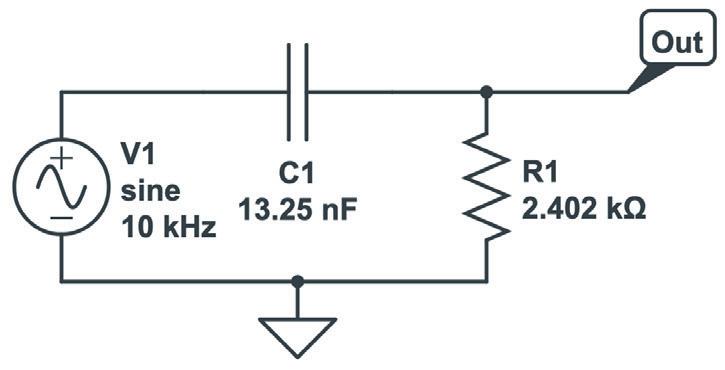
Figure 2.7: Circuit of a first-order RC low-pass filter
Below is a simple Python script that generates an unfiltered signal and its filtered version using a basic low-pass filter model:
import numpy as np import matplotlib.pyplot as plt from scipy.signal import butter, filtfilt
# Create a time array t = np.linspace(0, 1, 1000) # 1 second duration, 1000 samples
# Create a signal: low-frequency signal + high-frequency noise low_freq_signal = np.sin(2 * np.pi * 5 * t) # 5 Hz component high_freq_noise = 0.5 * np.sin(2 * np.pi * 250 * t) # 250 Hz noise signal = low_freq_signal + high_freq_noise
# Design a simple first-order Butterworth low-pass filter cutoff_frequency = 20 # 20 Hz cutoff b, a = butter(N=1, Wn=cutoff_frequency / (0.5 * 1000), btype='low') # N=1 for first-order
Chapter 2 • What is a filter?
# Apply the filter filtered_signal = filtfilt(b, a, signal)
# Plotting
plt.figure(figsize=(12, 6))
plt.plot(t, signal, label='Unfiltered Signal', alpha=0.7)
plt.plot(t, filtered_signal, label='Filtered Signal', linewidth=2)
plt.xlabel('Time (seconds)')
plt.ylabel('Amplitude')
plt.title('Unfiltered vs. Filtered Signal')
plt.legend()
plt.grid(True)
plt.show()
This script generates a signal that combines a low-frequency sine wave with high-frequency noise. It then applies a simple first-order low-pass filter with a cutoff frequency of 20 Hz. Finally, it plots both the original and the filtered signal for easy comparison.
Here is the plot:
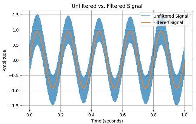
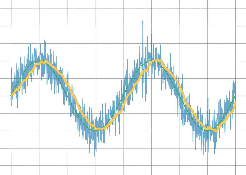
Figure 2.8: An unfiltered signal (blue) passes through a filter and emerges as a filtered signal (orange)
What do we see in the plot?
When you run this simulation, you will notice the following:
• The unfiltered signal (blue) looks very noisy and messy. It is difficult to clearly see the underlying slow movement of the signal.
• The filtered signal (orange) appears much smoother. The unwanted fast variations are greatly reduced, making it easier to see the true behaviour of the original low-frequency signal.
This is the essence of what a filter does: it improves the quality of a signal by removing unwanted parts without disturbing the useful information too much.
Later in the book, you will learn how the resistor and capacitor work together to create the filtering effect. You will also learn how to calculate the cutoff frequency and how different filters affect different types of signals. For now, it is enough to see that even a very simple circuit can have a big impact on the quality of the information that a system processes.
Introduction to Electronics: Filters is your comprehensive guide to understanding, designing, and applying first-order electronic filters using resistors, capacitors, and inductors. Whether you are a student, maker, or educator, this book demystifies the theory behind RC and RL filters and bridges the gap between concepts and real-world applications through simulation and experimentation. From the basics of frequency response and phase shift to hands-on breadboard builds and Python-based simulations, this book offers a deeply practical learning experience. You will learn to analyse filters using Bode plots and phasors, and explore applications in audio tone shaping, sensor signal conditioning, noise reduction, and power supply filtering. As you progress, you’ll build, measure, simulate, and tune filters using modern tools like CircuitLab, Python, and the Analog Discovery 3. Each chapter includes thoughtfully crafted activities that reinforce learning by doing—designing filters for specific tasks, simulating dynamic behaviour, and observing how theory translates into performance. Inside you’ll find:
> A clear introduction to the fundamentals of electronic filters
> Detailed explanations of RC and RL filters, cutoff frequency, and phase
> Guided activities using both simulation and hardware tools
> Real-life applications in audio, sensors, power supplies, and more
> A beginner-friendly primer on Python and algebra for electronics
Whether you’re working through simulations or experimenting with real components on your workbench, this book will help you develop a solid understanding of electronic filters and their role in practical circuits.
Peter Dalmaris is an educator, engineer, and lifelong learner. He is the founder of Tech Explorations, where he creates online courses and books that empower electronics enthusiasts, STEM educators, and students around the world. With a background in engineering and academic teaching, Peter is known for his hands-on, accessible approach to technical education. His work combines theory with practice, helping learners of all levels build confidence through making and experimentation.
Elektor
www.elektor.com