www.scientistlive.com
December 2024
EUROPEAN LABORATORY TECHNOLOGY
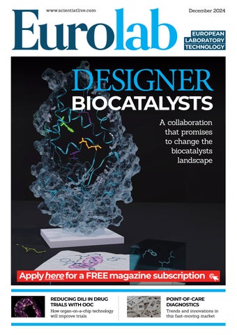
DESIGNER BIOCATALYSTS A collaboration that promises to change the biocatalysts landscape
Apply here for a FREE magazine subscription REDUCING DILI IN DRUG TRIALS WITH OOC
POINT-OF-CARE DIAGNOSTICS
How organ-on-a-chip technology will improve trials
Trends and innovations in this fast-moving market