Deta Electrical is a market leading manufacturer and distributor of wiring, lighting, cable management and electrical installation accessories, with a reputation for unrivalled quality, reliability, service and value for money.
Established in 1976, Channel is a leading manufacturer of emergency lighting, assistance products and door entry systems, and a key distributor for the UK’s leading fire detection system brands. Renowned for the breadth and depth of each product range, Channel has gained a loyal customer base driven by an excellence in technical and customer support. Proud to be affiliated with ICEL, LIA and EDA, Channel are members of the Apollo Partner Plus programme.
Deta’s mission is to use its passion and expertise to provide best-in-class products that meet and exceed ever-changing customer needs.
A brand trusted by customers, Deta is synonymous with high product quality, extensive product knowledge and exceptional customer service. Robust quality control throughout the development and manufacturing stages are key to delivering quality products.
Focused on continuous progression, Deta is committed to investment in innovation, product design and ease of installation. Digitalisation is at the heart of Deta’s strategy, supporting stakeholder requirements and maximising its value chain.
Deta is committed to protecting the environment for future generations, to building an inclusive community and to ensuring it acts in the best interests of society.


Overview
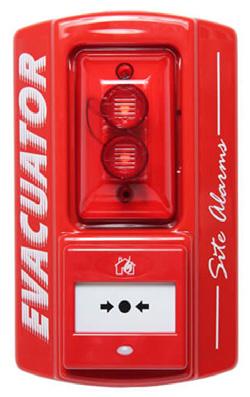
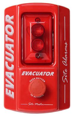
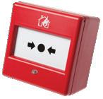
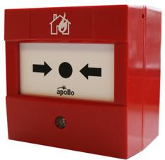
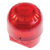
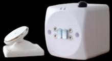
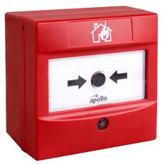
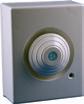
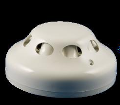
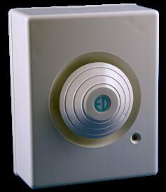
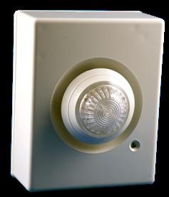
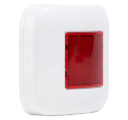
The Site Master Plus is an easily installed, simple to operate, reliable site alarm. These units require no external wiring (unless you wish to link to other Evacuator products), are manufactured using high quality components and feature an extremely loud 118dB sounder.
Features
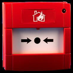
• Operated by a Manual Call Point
• Complete with reset key and resettable membrane
• Easily installed and requires no external wiring
• Link products using two core cable
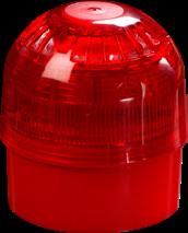
• Integrated high power flashing strobe
• Extremely loud 118dB sounder
• Powered by 9V PP3 battery
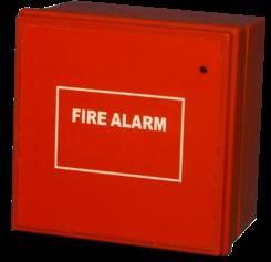
• Optional call point cover
• Can be linked to other Evacuator products
• Manufactured in the UK
Site Master Wired Standalone/Linked System
F/CHEV/BGU Stand alone break glass call point fire alarm, 118Db sounder
F/CHEV/PB Stand alone push button alarm, 118Db sounder
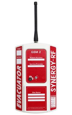
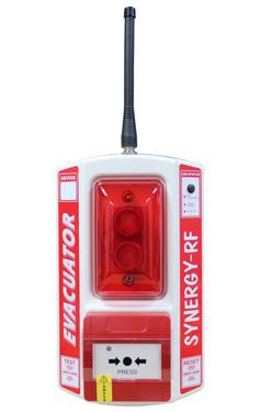
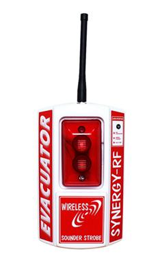
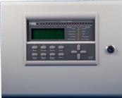
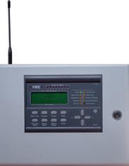
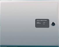
Overview
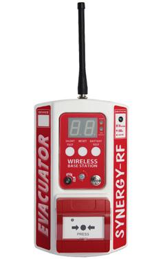
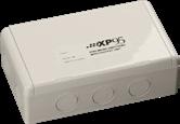
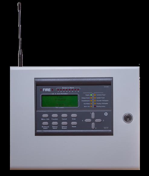
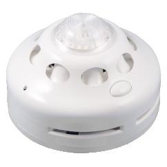
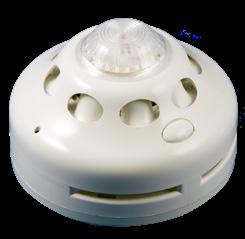
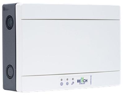
The Evacuator Synergy -RF wireless site alarm requires no cabling and can be wirelessly interconnected with up to 40 call points, sounder/strobe and detection Synergy RF devices within a single system. The base station acts as the systems control panel, featuring a screen to display when the system is in test or alarm state and monitors all linked devices in case of low battery. Each linked site alarm, including the base station, is given a numerical “address” allowing the triggered device to be easily identified.
Features
• Category 1 radio module
• 25mm bright LED display unit
• Scratch resistant UV decals
• 85dB buzzer
• 40 addressable zones
• Automatic battery low indication
• Completely wireless operation (No mains required)
• ‘Plug and play’ simple self
• Low maintenance costs
• Silent range test
• Battery Powered
F/CHEV/SYN/BS Wireless Master unit with break glass call point 85Db sounder
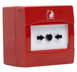
F/CHEV/SYN/BGU Wireless break glass call point fire alarm, 108Db sounder & strobe
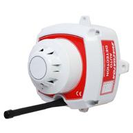
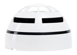
F/CHEV/SYN/SD Wireless smoke detector 108Db sounder
F/CHEV/SYN/HD Wireless heat detector, 108Db sounder
F/CHEV/SYN/SDWS Wireless smoke detector with sounder, 108Db sounder
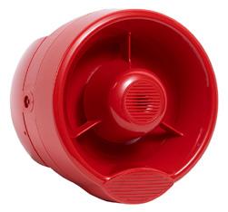
F/CHEV/SYN/SS Wireless sounder strobe
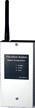
F/CHEV/SYN/GSM Wireless GSM dialer
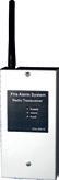
F/CHEV/SYN/INT2 Wireless relay interface
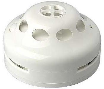
Overview
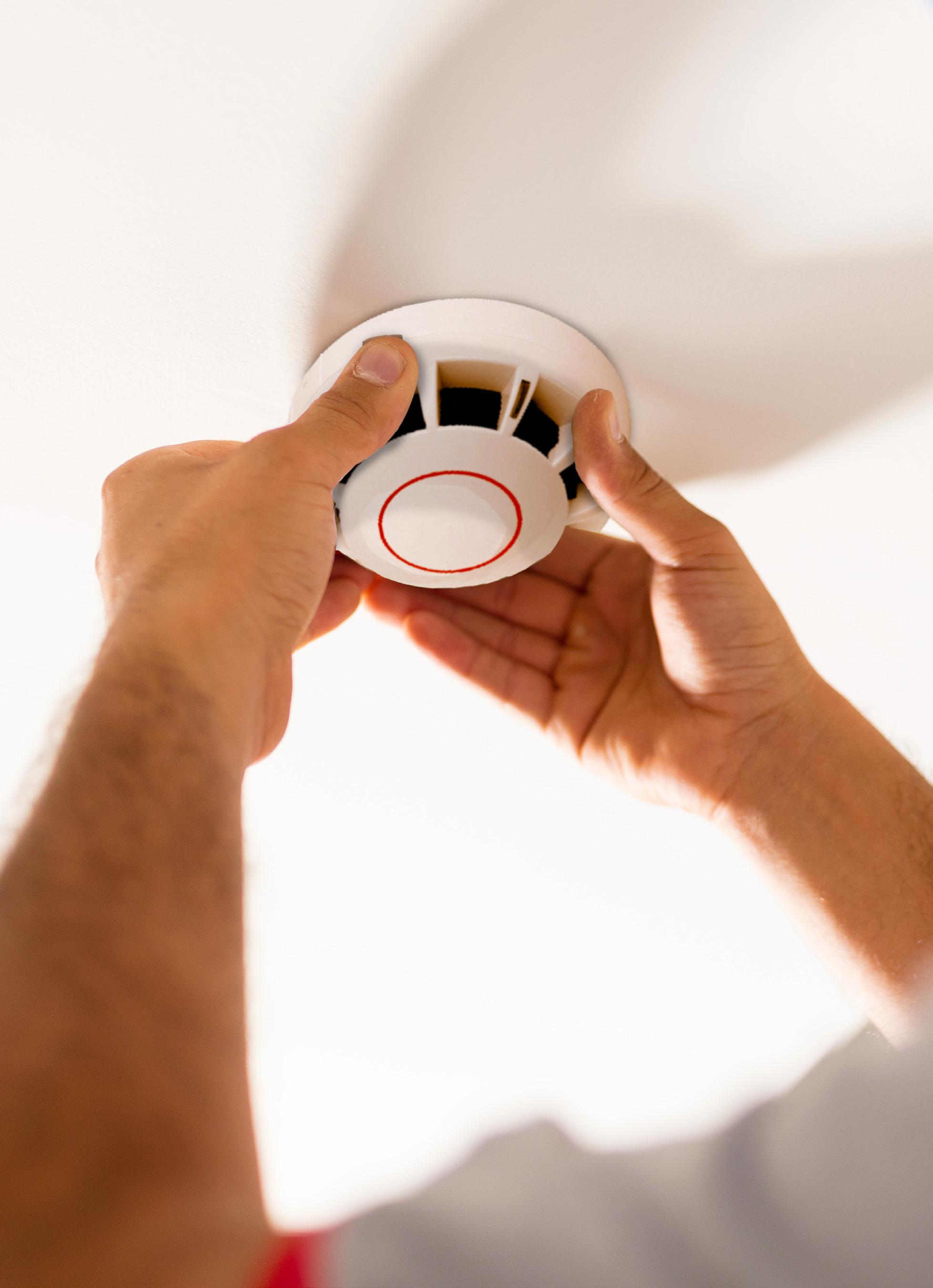
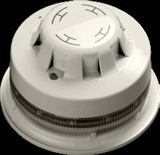
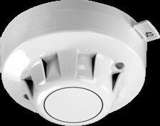
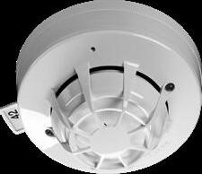
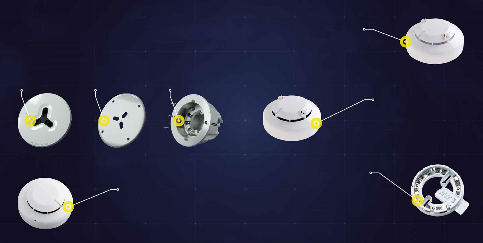
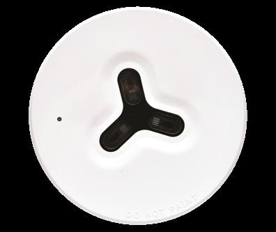
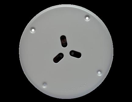
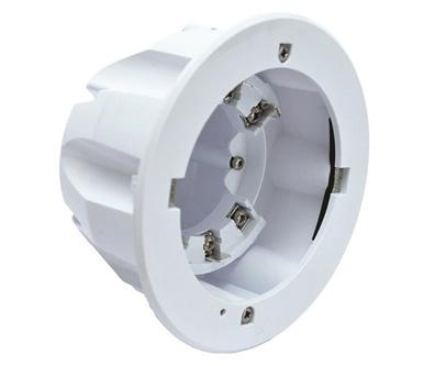
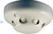
Our range of mains powered optical smoke and heat alarms with back-up power options of either 9V replaceable or 10-year sealed in non-replaceable battery, satisfying both Grade D2 and D1 domestic requirements respectively as laid down by BS 5839: Part 6 and the Building Regulations of England and Wales, Scotland and Northern Ireland.
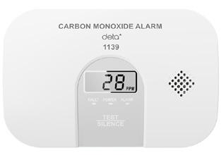
A Carbon Monoxide alarm compliments the range.
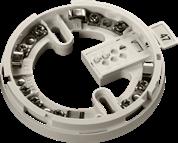
All alarms supplied with base making installation easier.
Features
• Optical alarms are suitable for all circulation areas and habitable rooms, making it ideal for hallways and landings, as well as living rooms and bedrooms
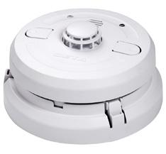
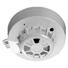
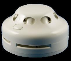
• Heat alarms are designed for areas where fumes or dust may cause nuisance alarms, making it ideal for kitchens, attics and garages
• CO alarm detect dangerous levels of Carbon Monoxide, making it ideal for installation in all rooms with fuel burning appliances
• High visibility dust covers supplied to prevent dust ingress during building works
• Linkable up to 12 optical, heat and Carbon Monoxide alarms in total for larger properties
• Alarms have missing battery indicator and mechanism that prevents installation of the alarm if the battery is missing
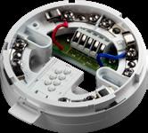
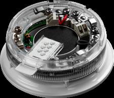
• Supplied with common mounting base that allows alarm to be pushed simply into place
• Mounting base has foam gasket built into mounting surface to prevent dust ingress
• Mounting base has large wiring space and fly lead electrical connection into alarm
• The input/output base allows interlinking to other systems
• 5 year guarantee
Domestic Detection
1163
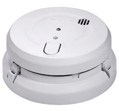
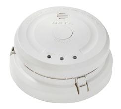
Mains Powered Optical Alarm with Replaceable 9V Battery Back-Up
1164 Mains Powered Optical Alarm with Tamper Proof Long Life Battery Back-Up
1165 Mains Powered Heat Alarm with Replaceable 9V Battery Back-Up
1166 Mains Powered Heat Alarm with Tamper Proof Long Life Battery Back-Up
1171 Mains Powered Combined Optical Smoke and Heat Alarm with Tamper Proof Long Life Battery Back-Up
1190 Wireless Alarm Controller for use with 1171 Combined Detector
1139 Battery Powered Carbon Monoxide Alarm (10 Year)
1169 Mains Powered Carbon Monoxide Alarm
1142 Carbon Dioxide & Temperature Monitor
1191 Input/Output Base
1192 Input/Output Base with Battery Back-Up - 10-Year Battery Life
Overview
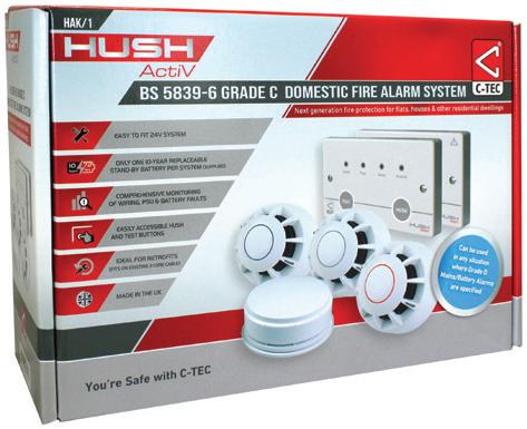
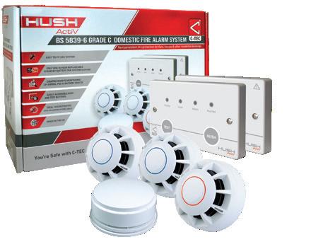
BS 5839-6 Grade C Domestic Fire Alarm Kit. Hush Activ is conventional stand-alone Grade C domestic fire detection and alarm system to BS 5839-6 (2019) ideal for use in flats, houses & other residential dwellings. Supplied as a cost-effective kit for ease of specification and ordering.
Features
• Includes all of the devices you need to create a typical LD2 dwelling system (additional ActiV detection and alarm devices available to accommodate larger systems or systems requiring LD1 coverage)
• Monitored for head removal, wiring, PSU and battery faults
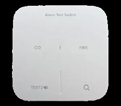
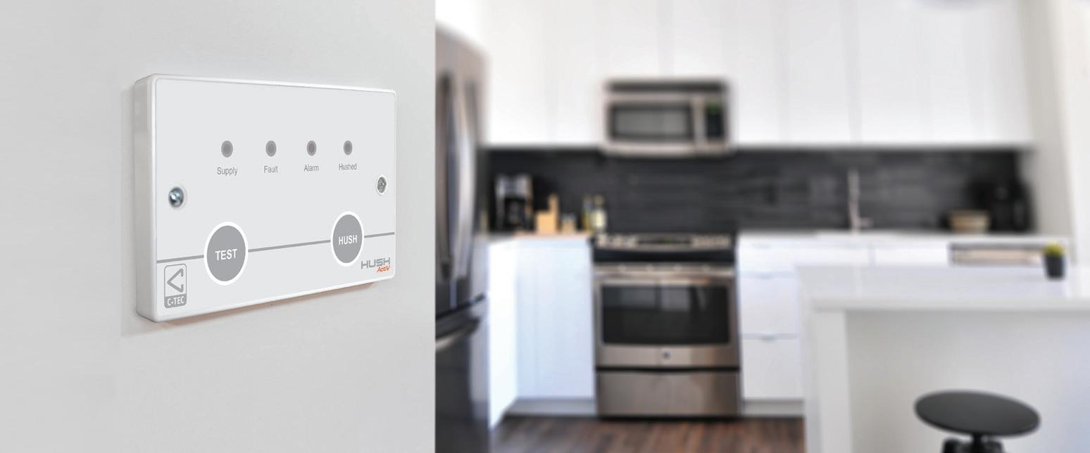
• Attractive double gang Hush-ActiV controller comes with its own rechargeable 72-hour standby battery and separate mains power supply unit
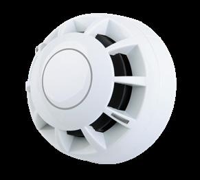
• Uses attractively designed EN54 certified detection and alarm devices
Hush ActiV Benefits
• Safer: Raises the typical level of fire protection in a dwelling from BS 5839-6 Grade D (unmonitored mains/battery alarms) to Grade C (monitored wiring and a central controller)
• Easy-To-Access User Controls: No need to stand on a chair to test or hush/silence devices
• Secure Monitored Wiring: All field wiring monitored for open and short circuit faults
• Environmentally Friendly: Up to 50% reduction in the mains power consumption of a typical grade D system, less plastic and only one replaceable lithium-ion battery per system providing over 72 hours’ standby
• Reduced Lifetime Ownership Costs: Separate fire detectors and sounders are less expensive to replace than mains/battery alarms and all smoke detectors have built-in drift compensation to increase service life expectancy
• No Intrusive BS 5839-1 Maintenance Visits: Monthly user/occupant test is sufficient
• Direct Grade D System Upgrades: Utilises the same wiring scheme as most mains/battery alarm solutions

F/CH/HAK/1
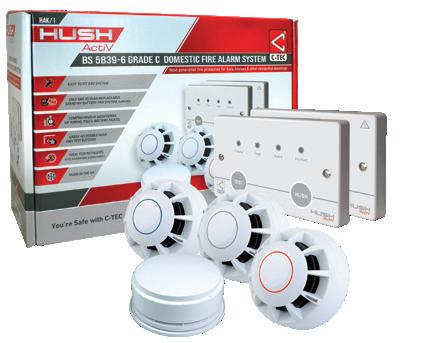
Contains:
• 1 x Hush ActiV Controller
• 1 x 230V/24V 250mA PSU
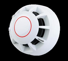
• 1 x ActiV Multi Sensor Fire Detector
• 1 x ActiV Heat Detector
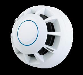
• 1 x ActiV Smoke Detector
• 3 x ActiV Detector Bases
• 1 x ActiV 96dBA Sounder
• 1 x ActiV Base Sounder Lid
Hush-ActiV Hak/1 Kit Wiring
230V/24V 250mA PSU
F/CH/HAK/2
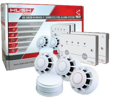
Contains:
• 1 x Hush ActiV Controller
• 1 x 230V/24V 250mA PSU
• 1 x ActiV Heat Detector
• 1 x ActiV Smoke Detector
• 3 x ActiV Detector Bases
• 1 x ActiV 96dBA Sounder
• 1 x ActiV Base Sounder Lid
Mounts on a standard UK 35mm double gang back box
Typical location: Adjacent to the dwelling’s Mains fusebox.
1-1.5mm2 twin + earth electrical cable
1-1.5mm2 standard triple + earth domestic electrical cable
ZONE +Ve COMMON -Ve
SNDR +Ve
HUSH-ACTIV CONTROLLER
c/w 72 HOUR STAND-BY BATTERY
Mounts on a standard UK 35mm double gang back box.
Typical location: In the entrance way at light switch height so its controls are accessible to dwelling occupants.
Multi Sensor (supplied)
ActiV Smoke Detector (supplied)
Optional additional ActiV alarm devices (voice sounders & visual alarm devices also available)
F/CH/HAK/3
Contains:
• 1 x Hush ActiV Controller
• 1 x 230V/24V 250mA PSU
• 1 x ActiV Multi Sensor Fire Detector
• 1 x ActiV Heat Detector
• 3 x ActiV Detector Bases
• 1 x ActiV 96dBA Sounder
• 1 x ActiV Base Sounder Lid
Optional Manual Call Point (not supplied)
Heat Detector (supplied)
Base Sounder (supplied)
Please note: HAK/2 and HAK/3 kits have a different mix of field devices. Component order on all kits can be changed to suit specific applications
BS 5839-6 Grade C Domestic Fire Alarm
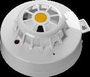
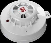
F/C4403A1R ActiV_Class A1R Rate-of-Rise Heat_Detector to EN54-5 (Needs base)
F/C4403A2 ActiV_Class A2 Standard (60ºC) Fixed Temp Heat_Detector to EN54-5 (Needs base)
F/C4416
F/C4414
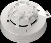
ActiV_Optical Smoke_Detector to EN54-7 (Needs base)
ActiV_Multi-Sensor Fire_Detector to EN54-5/7 (Needs base)
F/C4408D ActiV_Diode Base
F/BF431C/CC/W ActiV Base mounted sounder – White
F/BF456C/CC/W ActiV Base mounted sounder/beacon
F/CLOOM Interface loom to link to other systems
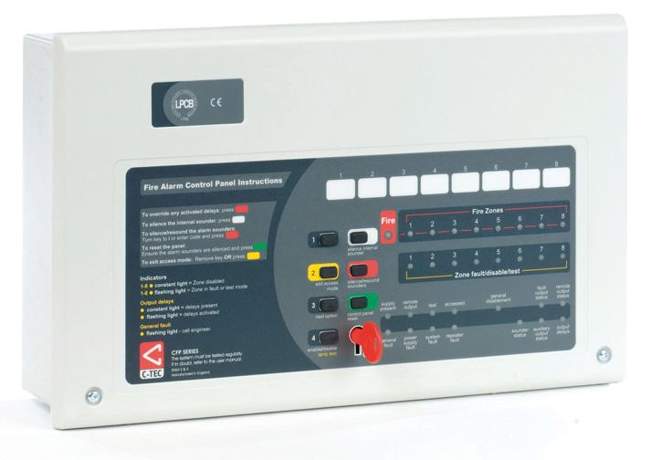
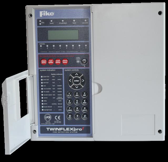
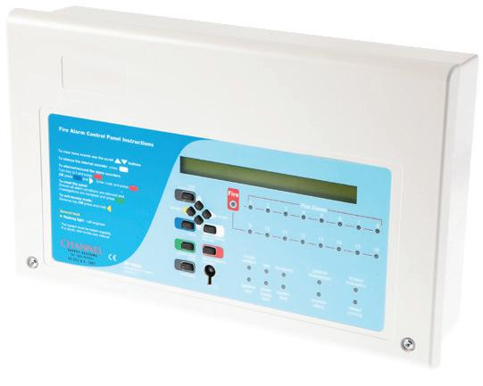
Features
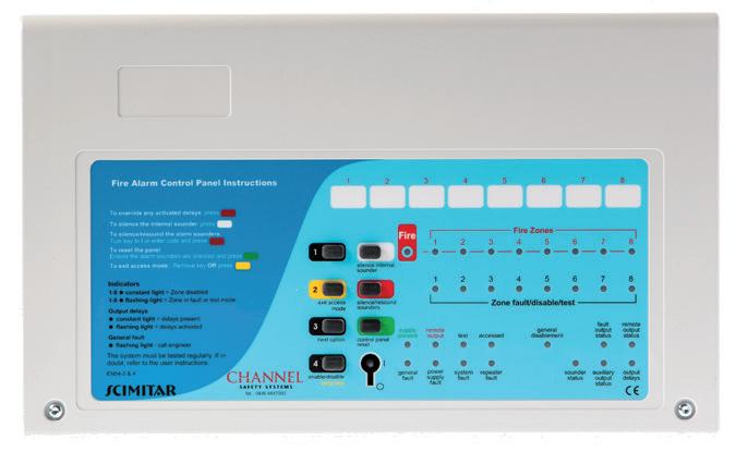
• LPCB certified to the latest versions of EN54 Parts 2 and 4
• Intuitive user-friendly interface with colour coded buttons and combined keypad/keyswitch entry to access level 2
• 2, 4 or 8 zone circuits (dependent on model purchased)
• Four conventional sounder circuits
• Integral 1.5A EN54-4/A2 compliant switch mode PSU
• Two on-board relays (Fire and Fault)
• Two open-collector outputs (Remote and Reset)
• ‘Class change’ and alert inputs
• Installer-friendly design accommodates easy first fix and straightforward maintenance
• Attractive flush or surface mountable plastic lid and enclosure – no bezel required
• Low 25mA quiescent current
• Multiple indicators
• End of line units included (one per zone)
• Ancillary system expansion connections provided for up to eight two-wire repeaters (one F/CHSC/RDC network driver card required per system)
Construction Plastic lid and base
Enclosure Finish RAL7035
IP Rating IP30
Panel Dimensions
380mm(W) x 235mm(H) x 96mm(D) 2, 4 & 8 panels have the same measurements
Weight 1.75 Kg (without batteries)
Enclosure Finish RAL7035 Textured
Requires 2x B/12V/3.2AH/SLA (Listed below)
Compatible Devices
Scimitar
Panels
F/CHSC/2
F/CHSC/4
F/CHSC/8
Batteries
Scimitar 2-zone panel requires 2 x B/12V/3.2AH/SLA battery
Scimitar 4-zone panel requires 2 x B/12V/3.2AH/SLA battery
Scimitar 8-zone panel requires 2 x B/12V/3.2AH/SLA battery
B/12V/3.2AH/SLA 12 Volt 3.2Ah sealed lead acid battery (1 block)
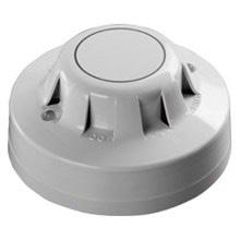
Apollo Series 65 Detectors
F/CHSM/P (55000-317) Optical smoke detector + base
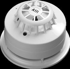
F/CHHF/A (55000-122) Rate of Rise & Fixed Temp (65oC) A1R Heat Detector + Base
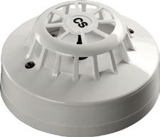
F/CHHF/A/HT (55000-137) Fixed Temp (100oC) CS Heat Detector + Base
F/CHHR/A/65 (55000-127) Rate of Rise & Fixed Temp (85oC) BR Heat Detector
F/CHHR/A/HT/65 (55000-132) Rate of Rise & Fixed Temp (100oC) CR Heat Detector
F/CHRI/60 Remote Indicator
Detectors Apollo protocol Series 65
Sounders & Visual Indicators
All compatible sounders and visual indicators are listed below.
Call Points
The most common call points are listed below.
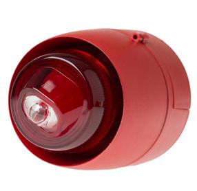
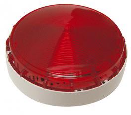
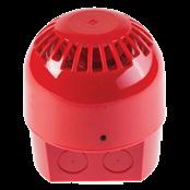
Sounders & Visual Indicators
F/CHWB/BN/RD/DB LED sounder beacon deep base
F/CHBN/RD/DB 24V Red LED beacon – deep base
F/CHBL/6/2 17-27V 6” Red fire bell
F/CHWB/R High output electronic sounder – white square
F/CHWB/RD/DB Electronic warbler/siren red – deep base
F/CHWB/D Base sounder white
F/CHBN/D/RING Beacon to fit over F/CHWB/D
F/CHWB/D/COVER/WH White cover to fit F/CHWB/
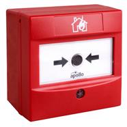
Call Points
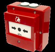
F/CHBG/S/5 Break glass – surface
F/CHBG/WP/3 Waterproof break glass
F/CHBG/S/5/CV Call Point Cover
S/BG/TESTKEY/1 Call Point Key
Repeater Panel
F/CHSC/R 8 zone repeater panel
F/CHSC/RDC Repeater driver card
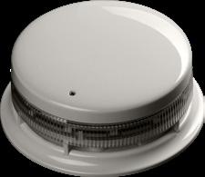
Overview
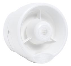
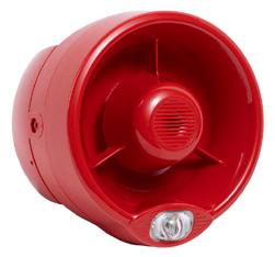
A European standard has been published to assess the performance of Visual Alarm Devices (VADs), which were often referred to as ‘beacons’ or ‘sounder beacons’.
They assist hearing impaired people or staff working in noisy environments to recognise when a fire alarm has been activated. EN54-23:2010 has been introduced to standardise the requirements, and performance of VADs to ensure that adequate light intensity is achieved where required.
There are 3 categories of VADs:
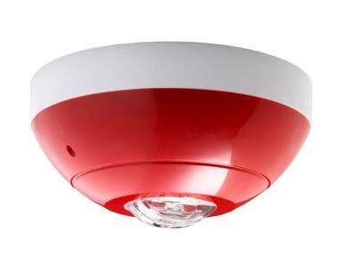
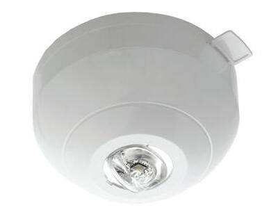
C Ceiling Mounted: When mounted on a ceiling a level of 0.4 lux is achieved over a known area
W Wall Mounted: When mounted on a wall a level of 0.4lux is achieved over a known area
O Open Category: Manufacturers specify the area coverage of the VAD.
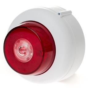
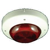
F/VAD/C/1
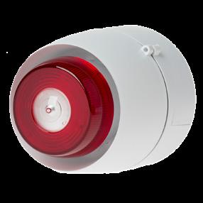
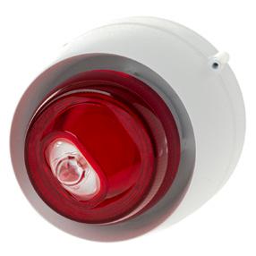
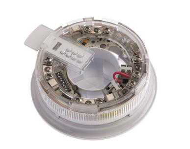
F/VAD/WB/C/2
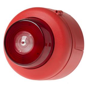
F/VAD/C/3
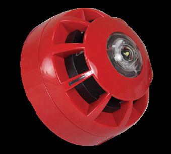
F/VAD/WB/C/4
F/VAD/WB/C/2
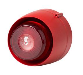
F/VAD/C/3 F/VAD/WB/C/4
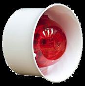
Ceiling mounted visual alarm device white body red flash. Shallow base. 25mA in alarm 7m @3m mounting height.
Ceiling mounted visual alarm device white body red flash with 98dB sounder deep base. 40mA in alarm 7m coverage @3m mounting height
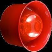
Ceiling mounted visual alarm device red body red flash. shallow base. 25mA in alarm 7m coverage @3m mounting height.
Ceiling mounted visual alarm device red body red flash with 98dB sounder. Deep base 40mA in alarm 7m coverage @3m mounting height
F/VAD/W/1
F/VAD/W/1
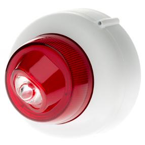
F/VAD/WB/W/2
F/VAD/W/3
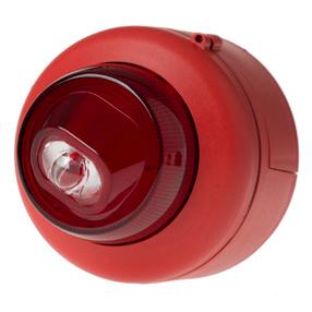
F/VAD/WB/W/4
F/VAD/WB/W/2
F/VAD/W/3
F/VAD/WB/W/4
Wall mounted visual alarm device white body red flash. Shallow base. 25mA in alarm 7m coverage @3m mouning height
Wall mounted visual alarm device white body red flash with 98dB sounder deep base. 40mA in alarm 7m coverage @3m mounting height
Wall mounted Visual alarm device red body red flash. Shallowe base. 25mA in alarm 7m coverage @3m mounting height
Wall mounted visual alarm device red body red flash with 98dB sounder. Deep base. 40mA in alarm 7m coverage @3m mounting height
Features
• A powerful C-TEC manufactured, LPCB approved EN54 compliant 2-wire fire alarm panel
• Designed to work with Apollo’s AlarmSense range of detectors, call points, sounders and beacons
• Available with 2, 4 and 8 AlarmSense zone circuits
• Installer-friendly design accommodates easy first fix and straightforward maintenance
• Attractive flush or surface mountable plastic lid and enclosure
• Auxiliary remote, fire, fault and reset outputs
• ‘Class change’ and alert inputs
• Four conventional sounder circuits (for use with non-AlarmSense sounders)
• Low quiescent current – for extended standby times with small batteries
• Intuitive user-friendly interface
• Multiple indicators provide a comprehensive overview of system status
• System expansion connections for up to eight two-wire repeater panels and a range of Relay Output Cards
• Wide range of engineering functions including zone test, coincidence, zone delay and non-latching zones
• Two on-board relays (Fire and Fault)
• Two open-collector outputs (Remote and Reset)
Panels
F/CHAS/2 AlarmSense 2-zone fire panel. Requires 2x B/12V/3.2AH/SLA batteries.
F/CHAS/4 AlarmSense 4-zone fire panel. Requires 2x B/12V/3.2AH/SLA batteries.
F/CHAS/8 AlarmSense 8-zone fire panel. Requires 2x B/12V/3.2AH/SLA batteries.
Repeater Panel
F/CHSC/R AlarmSense 8 zone repeater panel. Requires 2 x B/12V/3.2AH/SLA batteries.
F/CHSC/RDC Repeater driver card
S/E20/A Relay card for use with AlarmSense (fitted in panel)
Batteries
B/12V/3.2AH/SLA 12 Volt 3.2Ah sealed lead acid battery (1 block)
Remote Indicator
F/CHRI/AS AlarmSense remote indicator (Not for use with sounder base units)
All panels require 2x B/12V/3.2AH/SLA batteries (Listed below)
Construction
Polycarbonate enclosure
Enclosure Finish RAL7035
Panel Dimensions
380mm(W) x 235mm(H) x 96mm(D) 2, 4 & 8 panels have the same measurements Weight 1.75 Kg (without batteries)
Call Points
F/CHBG/S/AS/2 (55400-894) AlarmSense surface break glass
F/CHBG/AS/COVER Call Point Cover S/BG/TESTKEY/AS Call Point Key
Apollo Detectors & Base
F/BASE/AS (45681-244) Base for use with AlarmSense detectors
F/CHHF/A/HT/AS (55000-193) AlarmSense fixed high temperature heat detector. Requires Base.
SP/CHSM/P/AS (55000-390) AlarmSense optical detector. Requires Base.
F/CHHF/AS (55000-190) AlarmSense 55˚ rate of rise heat detector. Requires Base.
Apollo Sounders & Visual Indicators
F/CHWB/D/AS (45681-510) AlarmSense base sounder
F/CHWB/D/BN/AS (45681-509) AlarmSense base mounted electronic sounder/beacon
Overview
Two-wire AlarmSense has been developed to make the design and installation of a fire detection and alarm system easier and more economic for small to medium sized buildings. The range also allows an existing system to be extended or modified if necessary, this flexibility makes AlarmSense an excellent choice for use in Houses of Multiple Occupation (HMO’s).
Most conventional fire systems are designed to work with two pairs of wires per zone: one pair for detection devices such as smoke detectors, heat detectors and manual call points; the other for alarm devices such as bells, sounders or strobes. By using different voltage bands for quiescent and alarm states, AlarmSense components can be connected to the same pair of supply wires.
When powered and controlled by the AlarmSense two-wire fire panel, this reliable technology takes all the complexity out of fire alarm system design, leading to quicker, less expensive and more flexible installations. Research shows an AlarmSense two-wire system can achieve up to 40% reduction of labour over a standard four wire conventional system.
SP/CHSM/P/AS Optical Smoke Detector
F/CHWB/D/AS & F/CHWB/AS/CAP/WH Base sounder with white locking cap
Batteries may vary due to
F/CHHF/A/HT/AS Heat Detector
F/CHWB/BN/RD/AS Red sounder visual indicator
F/CHHF/HT/AS + F/CHWB/D/AS
Heat detector base C/W sounder base
F/CHWB/RD/AS Red sounder
Apollo products are certified in a global arena to meet the most exacting standards set by both our customers and the dynamic and challenging environments in which they are designed to operate.
Apollo holds in excess of 2500 product approvals worldwide. Their products are stringently tested to international land and marine based standards. The company is quality certified by LPCB to ISO9001:2008 and ISO14001:2004 for their Environment Management System.
SP/CHSM/P/AS + F/CHWB/D/BN/AS
Smoke detector base C/W sounder base
F/CHBG/S/AS/2 Surface mounted break glass
Features
• Complies to BS 5839 and EN54 part 4
• 32 devices per zone
• Output module available for plant shutdown or door release
• Panels are supplied without battery – options are listed
• 4 line x 20 character LCD display
• Ability to differentiate between callpoint or detector alarms
• Checkpoint alarm verification procedure
• Highlighted selection menu
• Event log storing up to 500 events
• 3 enhanced test modes
• Allows detectors & sounders to be installed on the same pair of wires
• Built-in EOL capability in all devices
• Use of Multipoint detector offers 7 modes of detection
• No extra devices needed for audible warning
• Self-calibrates every 6 hours
• Continuously monitors for dust contamination
Construction 5VB rated ABS
Battery Charger 170 mA current limiter
Battery (reverse polarity) 3.2AH F 20mm (in line with battery leads) Glass
Panel Dimensions Fascia 331mm2 – Back box 305mm – Depth 99mm
Weight
Sabre Pro -
Panels
F/CHSA/2/PRO
F/CHSA/4/PRO
F/CHSA/8/PRO
Sabre Pro 2 zone dual wire fire alarm panel (requires 2 x B/12V/3.2AH/SLA batteries)
Sabre Pro 4 zone dual wire fire alarm panel (requires 2 x B/12V/3.2AH/SLA batteries)
Sabre Pro 8 zone dual wire fire alarm panel (requires 2 x B/12V/3.2AH/SLA batteries)
F/CHSA/PRO2/R Sabre Pro repeater panel for 4 and 8 zone panels only
Remote Indicator
F/CHRI/60 Remote indicator
Batteries
B/12V/3.2AH/SLA 12 Volt 3.2Ah sealed lead acid battery - 2 required
Detectors
F/CHSA/SH/PRO Sabre combined optical smoke/heat detector
F/CHSA/SHS/PRO Sabre combined optical smoke/heat detector and sounder 90dBA
F/CHSA/SHSB/PRO Sabre combined optical smoke/heat detector and sounder/beacon 90dBA
Batteries are not included, all panels require 2x B/12V/3.2AH/SLA to operate, listed below. 2
Sounders & Visual Indicators
F/CHBN/SU/SA Sabre sounder/strobe wired on zone 90dBA
F/CHSU/I/SA Sabre industrial horn sounder 90dBA IP55
F/CHSU/SA Sabre red electronic sounder unit
Call Points
F/CHBG/S/SA/CV Sabre series break glass call point complete with cover
F/CHBG/S/SA/WP Sabre series IP65 break glass call point
S/BG/COVER/SA Call Point Cover
S/BG/TESTKEY/SA Call Point Key
Input/Output Modules
F/CHSW1/SA Sabre input/output module
Other Accessories
F/CHHRT/SA/PRO Sabre head removal tool
F/CHSA/4CONV Expansion card for 4 zone panel to add 4 conventional zones (4 zone panel only)
F/CHSA/4/PRO/CARD 4 Zone expansion PCB to add 4 x two wire zones (4 zone panel only)
F/CHSA/SH/PRO, F/CHSA/SHS/PRO & F/CHSA/SHSB/PRO
F/CHBN/SU/SA
Sounder/Strobe wired on zone
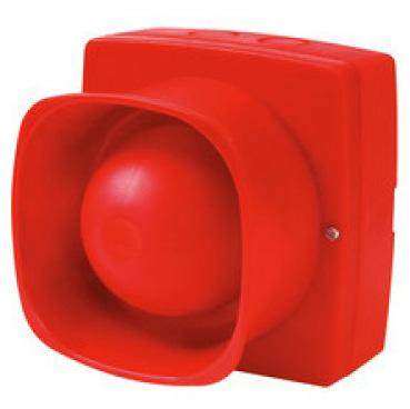
F/CHSU/I/SA Industrial Horn Sounder

F/CHSU/SA Electronic Sounder Unit
F/CHBG/S/SA/CV Break Glass Call Point
Please note: Only Sabre Pro detectors, combination detectors/sounders, call points and sounders & visual indicator devices should be used with Sabre Pro panels.
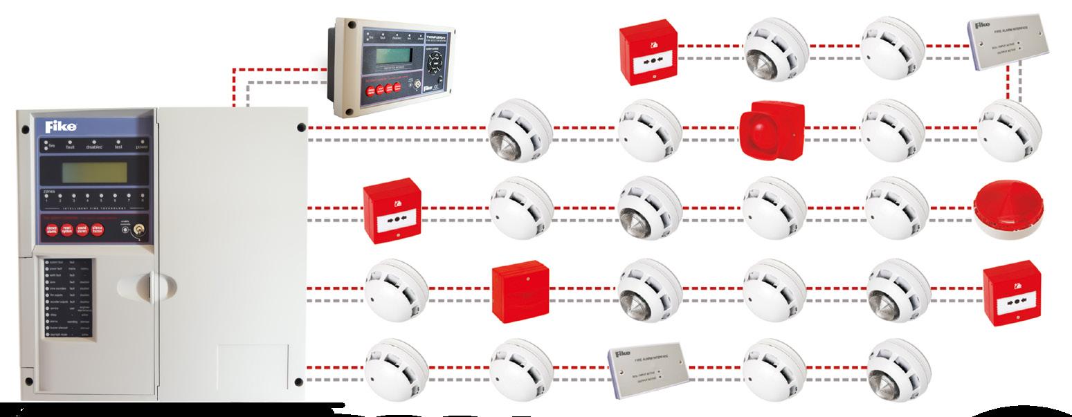
Overview
Typical system architecture diagram shows a typical installation of a 2 wire, 4/8 zone detection system.
Each fire detection system is bespoke to each premises’ – Channel Safety Systems can offer complete system designs, based on contract awarded.
Features – Cut False Alarm Costs
• Drift-compensation reduces false alarms, but this feature is not normally found in conventional or two wire systems
• The Sabre detector not only has this feature as standard, but when it reaches its upper limit there is a warning on the panel and at the detector
• The Sabre Pro system also has an in built pre alarm facility that can be programmed through the control panel. This “Alarm Confirmation” feature can significantly reduce the effect of nuisance alarms
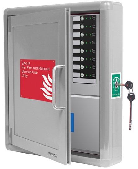
BS 8629:2019 Evacuation Alert Control & Indicating Equipment (EACIE)
Following recent fire in numerous high rise buildings, BS 8629:2019 now gives guidance on Evacuation Alert Systems which are recommended in blocks of flats to assist the Fire and Rescue Service (FRS) in evacuating part or all of a building in an emergency.
In domestic buildings with a storey more than 18m above ground level, an evacuation alert system should be provided to enable the fire and rescue services to initiate operation of fire alarm sounders within each dwelling on any single floor, multiple floors and the entire building, according to circumstances.
Separate to the fire alarm system, the EACIE system allows the fire brigade to evacuate any or all zones at the flick of a switch.
Toggle switches and LED indication will make viewing evacuation zone status and implementing evacuation strategies quick, simple and straightforward.
Each EACIE panel is housed in its own security-rated enclosure with a BS EN 1303-compliant lock and key mechanism for exclusive access by the fire and rescue service – ensuring minimal risk of unauthorised use.
The EACIE will work with hard-wired, radio and/or hybrid systems.
Is it Mandated?
As of December 1st 2022, BS 8629 was incorporated into Approved Document B (UK Building regulations) as a result any new residential building over 18m in height is required to have an Evacuation Alert system by law.
Please note: As each system needs to be individually designed, please contact us for further information
Features
• Compatible with Apollo’s XP95/Discovery and Hochiki’s ESP protocols
• The ability to interconnect up to eight Firewatch main panels (any variant) onto a two wire RS485 network. Alternatively, up to eight Firewatch repeaters can be connected to a non-networked Firewatch main panel
• Combined keypad/keyswitch entry to access levels 2 & 3
• Two independently programmable conventional sounder circuits
• Two programmable inputs
• A fault output relay and three programmable relay outputs with voltage free changeover contacts
• Three zone dependency functions (A, B & C to EN54-2 clause 7.12)
• A day/night (building occupied/unoccupied) function
• An investigation delay period function
• A phased evacuation and delays to outputs facility to EN54-2
• An alarm counter that records the number of times the panel has been in an alarm state to EN54-2
• Powerful short circuit protected loop drivers, capable of supporting up to 40 loop powered 10mA sounders per loop
• An integral EN54-4/A2 switch mode PSU rated @ 185-260V AC
• 50-60Hz (1.4A on a 16 zone panel, 3A on a 32 zone panel)
• Earth fault monitoring
• An easy to read, 80 character back-lit display
• 40 characters of custom text per device
• 999 event monitoring
• Comprehensive test facilities to EN54-2 and a wide range of functions including auto-learn loops, monitor a point, test outputs, one man walk test and loop continuity test
• An intuitive Windows based upload-download PC program that allows the system to be programmed quickly and easily
Internal Power Supply
Earth Fault Monitoring
27V DC Nominal
Yes (any conductor)
Max. No. of Addressable devices per loop 126
Max. No. of Addressable devices per loop @ 10mA 40
Firewatch Panels
FW1001 Panels
F/FW1001/1/16
F/FW1001/1/32
F/FW1001/2/32
Networkable single loop 16 zone panel (requires 2 x B/12V/3.2AH/SLA batteries)
Networkable single loop 32 zone panel (requires 2 x B/12V/3.2AH/SLA batteries)
Networkable two loop 32 zone panel (requires 2 x B/12V/7AH/SLA batteries)
F/FW1001/R/16 Networkable repeater panel – 16 zones (requires 2 x B/12V/3.2AH/SLA batteries)
F/FW1001/R/32
F/FW1001/NCC/32
F/FW1001/NCC/16
Which Protocol?
Firewatch FW1001 Panels are compatible with Apollo XP95/ Discovery and Hochiki/ESP devices – please see pages 78-83 (Hochiki panel needs to be ordered if using Hochiki devices). Batteries are not included.
Panel Batteries
B/12V/3.2AH/SLA 12 Volt 3.2Ah sealed lead acid battery (1 block)
B/12V/7AH/SLA 12 Volt 7Ah sealed lead acid battery (1 block)
Hush Buttons
F/FW1001/HB BS 5839-6 Hush button, Apollo XP95/Discovery
Networkable repeater panel – 32 zones (2 x B/12V/7AH/SLA batteries)
Network communications card for 32 zone for main panel
Network communications card for 16 zone for main panel
Please note:
• Batteries are not included
• Please state when ordering whether you require Apollo or Hochiki protocol
• Batteries may vary due to stand-by times and number of devices on your system. or email technical@channelsafety.co.uk


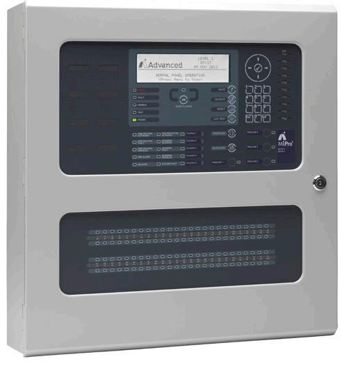
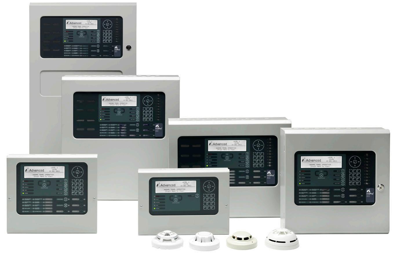
Overview
Whether you want to minimise false alarms, integrate with building management systems or remotely monitor networked sites, MxPro 5’s high-performance solutions bring you peace of mind that your fire system is actively protecting people and property.
Its intuitive programming, powerful networking, comprehensive cause and effect and unique diagnostic features put you in complete control of your fire protection.
Available in a range of flexible formats and supporting four leading detector protocols, MxPro delivers performance, quality and ease of use.
Every MxPro 5 features Advanced’s unbeatable networking capabilities and Dynamix Tools fire panel software making it is easy to use and configure, from the smallest to the largest of sites and with complicated cause-and effect.
Features
• 1, 2, 4 or 8 loop formats
• Up to 254 devices per loop (protocol dependent)
• Up to 200,000 devices per network
• Networkable up to 200 nodes
• Built in voltage and current meters
• On board or optional remote battery temperature sensor
• Advanced’s simple select and click programming and configuration
• Quick start and protect
– A working system after an Auto learn is performed
• 20 built-in, fully programmable LEDs
• 5000 event log entries
• 201 programmable false alarm management areas per panel
• Timed enablement of isolated zones, input and output devices
• Backward compatibility with MxPro 4 network
• Approved to EN54 Parts 2, 4 and 13
• Certified by FM Approvals to EN54 Parts 2 and 4
• Autolearn and loop detection
• Up to 2000 fire detection zones
• True peer-to-peer networking
• Supports intelligent/programmable remote terminals, BMS interface, IP Gateway and I/O Drivers
• Circuit monitoring from any panel or repeater
• Direct USB and RS232 PC connections
• Peripheral expansion built in
• 4 programmable push buttons
• Complete device history from each panel
• Programmable screen logo
• Advanced logic delivering huge configuration opportunities
• Compatible with Apollo, Argus, Hochiki and Nittan protocols

F/CH/MX-5101 1-Loop fire panel in small enc. (Comes with 20 zone LED indicators)
F/CH/MX-5201 1-2 Loop fire panel C/W 1 Loop card in Medium enc. (Comes with 20 zone LED indicators)
F/CH/MX-5202 1-2 Loop fire panel C/W 2 loop cards in Medium enc. (Comes with 20 zone LED indicators)
F/CH/MX-5401 1-4 Loop fire panel C/W 1 Loop card in Large enc. (Comes with 20 zone LED indicators)
F/CH/MX-5402 1-4 Loop fire panel C/W 2 Loop cards in Large enc. (Comes with 20 zone LED indicators)
F/CH/MX-5403 1-4 Loop fire panel C/W 3 Loop cards in Large enc. (Comes with 20 zone LED indicators)
F/CH/MX-5404 1-4 Loop fire panel C/W 4 Loop cards in Large enc. (Comes with 20 zone LED indicators)
F/CH/MX-5802 2-8 Loop fire panel C/W 2 Loop cards. Standard network (Comes with 20 zone LED indicators)
F/CH/MX-5803 2-8 Loop fire panel C/W 3 Loop cards. Standard network (Comes with 20 zone LED indicators)
F/CH/MX-5804 2-8 Loop fire panel C/W 4 Loop cards. Standard network (Comes with 20 zone LED indicators)
F/CH/MX-5805 2-8 Loop fire panel C/W 5 Loop cards. Standard network (Comes with 20 zone LED indicators)
F/CH/MX-5806 2-8 Loop fire panel C/W 6 Loop cards. Standard network (Comes with 20 zone LED indicators)
F/CH/MX-5807 2-8 Loop fire panel C/W 7 Loop cards. Standard network (Comes with 20 zone LED indicators)
F/CH/MX-5808 2-8 Loop fire panel C/W 8 Loop cards. Standard network (Comes with 20 zone LED indicators)
F/CH/MXP-503 Standard Network card. Used for repeater panels & networking main panels
F/CH/MXP-903 Fault tolerant Network card. Used for repeater panels & networking main panels
F/CH/MX-5010 Remote Display only
F/CH/MX-5020 Remote Display with controls
F/CH/MXP-513M-050RD 50 Zone LED card
Larger zone cards available
Overview
The XP95 range of analogue addressable fire detectors is advanced in design, improved in performance and has unique features that benefit the installer and the end user.
The detectors have been carefully researched and developed by the Apollo design team and the range has ndergone rigorous testing to ensure that it meets not only European and other standards but also the demands of today’s high technology environments.
XP95 detectors provide an alarm facility that automatically puts an alarm flag on the data stream and reports its address when the pre-set EN54 thresholds are exceeded.
F/CHBG/IS/95/2 F/CHBG/WP/95/1
Cell Points
S/BG/TESTKEY/AS Call Point Test Key
F/CHBG/IS/95/2 (TP SA5900-908) Analogue addressable break glass – complete with isolator and flexible element
F/CHBG/AS/COVER Call Point Cover
F/CHBG/WP/95/1 (58200-950) XP95 weatherproof break glass
F/CHWB/BN/95/AP
F/CHBN/95 (55000-877) XP95 loop powered beacon – requires F/BASE/95
F/CHBN/BASE/95 (45681-339) Beacon with detector base
F/CHWB/95/AP (55000-001) Open area XP95 sounder red IP65 complete with isolator
F/CHWB/BN/95/A (45681-331) Loop powered base sounder beacon – incorporates detector mounting base
F/CHWB/BN/95/AP (55000-005) Open area XP95 sounder beacon red IP65
F/CHWB/BN/95/IS (45681-330) Loop powered base sounder beacon – complete with loop isolator and detector mounting base
F/CHWB/IS/IN/95A (45681-277) Loop powered intelligent base sounder – incorporates detector mounting base
F/COVER/RD/1 (45681-293) Red cover for CHWB/BN/95/A
F/COVER/WH/1 (45681-292) White cover for CHWB/BN/95/A
Features
• Digital Protocol for error-free transmission
• Alarm Flag for fast alarm reporting
• Alarm Address for fast location of alarm
• Automatic addressing with the patented XPERT card
• Electronics-free, easy fit base
• Ease of installation
• Wide range of compatible interface units
• Wide range of compatible panels
• Compatible with Series 90 and Discovery
• Elegant, unobtrusive design
• Wide range of products
• Great flexibility in system design
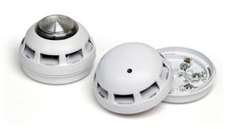
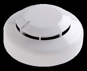
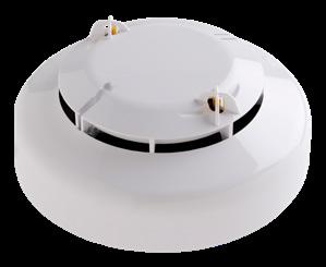
Top Row: F/CHSM/P/95, F/CHHM/95, F/CHHM/HT/95
Bottom Row: F/BASE/95, F/CHSM/M/95
XP95 Detectors
F/CHHM/95 (55000-400) Temperature monitor less base
F/CHHM/HT/95 (55000-401) High temperature H D less base
F/CHSM/M/95 (55000-885) Multi-sensor detector
F/CHSM/P/95 (55000-600) Optical smoke monitor less base
Interfaces & Isolators
F/CHIO/1/95 (SA4700-102) Single channel input/ output unit complete with isolator. Contacts rated 30V 1Amp
F/CHIO/1/95/240 (SA4700-103) Single channel input/ output unit 230V contacts 1A complete with surface mounting enclosure
F/CHIO/2/95 (SA4700-104) Twin channel input/output unit complete with isolator
F/CHSN/95 (55000-852) Sounder circuit controller complete with isolator
F/CHSW/95/P (SA4700-100) Switch monitor complete with isolator
F/CHZM/IS/95 55000-845 Zone monitor
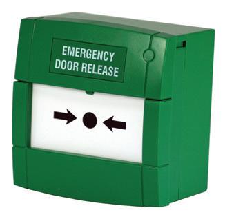
F/CHDR/95
Loop Powered Door Release
F/CHDR/95 (55000-982) XP95/Discovery Loop Powered Door retainer
Overview
A European standard has been published to assess the performance of Visual Alarm Devices (VADs), which were often referred to as ‘beacons’ or ‘sounder beacons’.
They assist hearing impaired people or staff working in noisy environments to recognise when a fire alarm has been activated. EN54-23:2010 has been introduced to standardise the requirements, and performance of VADs to ensure that adequate light intensity is achieved where required.
There are 3 categories of VADs:
C Ceiling Mounted: When mounted on a ceiling a level of 0.4 lux is achieved over a known area
W Wall Mounted: When mounted on a wall a level of 0.4lux is achieved over a known area
O Open Category: Manufacturers specify the area coverage of the VAD.
F/55000-742
F/55000-745
F/55000-741
F/55000-744
F/BF451A/CX/SRC
Ceiling Mounted 55000-742 XP95/Discovery Red body, White flash
9.4mA in alarm 8.5m coverage @3m mounting height
Ceiling Mounted 55000-745 XP95/Discovery White body, White flash 9.4mA in alarm 8.5m coverage @3m mounting height
F/45681-709
F/45681-705
Wall Mounted 55000-741 XP95/Discovery Red body, White flash.
9.4mA in alarm 6m³ coverage @2.4m mounting height
Wall Mounted 55000-744 XP95/Discovery White body, Red flash.
9.4mA in alarm 6m³ coverage @2.4m mounting height
Wall Mounted Sounder/VAD W-3-3.1 VAD C/W 91dB(A) Sounder
Open Category 45681-709 XP95/Discovery
BASE MOUNTED VAD – White flash
9.4mA in alarm. Approx coverage 3m Dia @ 3m mounting height
Ceiling Mounted 45681-705 XP95/Discovery
BASE MOUNTED SOUNDER/VAD – White flash. 14mA in alarm. Approx coverage 3m Dia @ 3m mounting height
Overview
Discovery is a range of high specification analogue addressable fire detectors. The Discovery range is designed to meet specifications for detectors incorporated in sophisticated systems, Discovery provides engineers with an additional dimension in fire protection capability.
The Discovery communications protocol is a development of the proven XP95 protocol, making both ranges of detector compatible.
Features
• Rejection of transient signals
• Flashing LED option
• Five response modes for ease of optimisation to changing environments
• Drift compensation to ensure constant sensitivity
• Four bytes of user programmable non-volatile memory
• Alarm flag for fast alarm reporting
• Conventional alarm facility during CIE processor fault
• 360° visibility in alarm
• Compatible with XP95 systems
Compatible Products
All Discovery smoke detectors include compensation for sensor drift caused, for example, by dust in the chamber, and will hold the sensitivity at a constant level even with severe chamber contamination.
Drift Compensation
Access to the Discovery range of audio visual signalling equipment with advanced features such as choice of volume, tones, including class change.
Sensitivity Selection
Access to the Discovery range of audio visual signalling equipment with advanced features such as choice of volume, tones, including class change.
F/CHBG/IS/DISC Break Glass complete with isolator
F/CHWB/BN/DISC/AP/R Open-Area Sounder Indicator – Red Lens
Sounders & Visual Indicators
F/CHSM/P/DISC Optical Detector less Base
F/CHWB/BN/DISC/A Sounder Visual Indicator Base
F/CHHM/DISC Heat Monitor less Base
F/CHSM/M/DISC Smoke/Heat Detector less Base
Apollo Detectors
F/CHSM/P/DISC (58000-600) Discovery Optical Detector Less Base
F/CHHM/DISC (58000-400) Discovery Heat Monitor Less Base
F/CHSM/M/DISC (58000-700) Discovery Smoke/Heat Detector Less Base
Apollo Sounders & Visual Indicators
F/CHWB/BN/DISC/A (45681-393) Discovery Sounder Visual Indicator Base
F/CHWB/BN/DISC/AP/R Open Area Sounder Indicator - Red Lens
Break Glass Call Points
F/CHBG/IS/DISC Break Glass Complete with Isolator
Please note:
• We have portrayed the most commonly used Discovery devices here – yet for further options please contact us.
• For interface units – XP95 interfaces on the previous page can be used. Contact our technical team at technical@deta.co.uk to check compatibility prior to ordering.
Overview
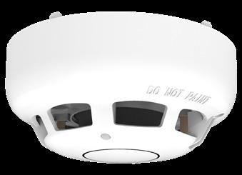
Hochiki’s Intelligent range of automatic fire detection and alarm equipment is designed and manufactured to the highest international standards, offering life safety products and systems of incomparable reliability. This extensive range of products includes high performance sensors, a wide selection of input and output modules, and ancillaries. All products use Hochiki’s high integrity communications link, ENHANCED SYSTEM PROTOCOL (ESP) that is fundamental to the range.
Specified in many prestigious buildings, ESP is a secure, expandable digital protocol that, together with Hochiki’s Intelligent range of devices, is the premier choice for system designers.
The protocol can support up to 240 different codes, ensuring that future products can be accommodated with ease.
Features
• Removable, high performance chamber
• Twin fire LEDs allow 360 viewing
• Locking mechanism (sensor to base)
• Variable sensitivity – Electronically addressed
• All base fixing centres are 48 – 74mm
• Approved by LPCB & VdS
Hochiki ESP Protocol
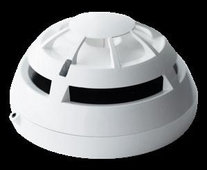
Detectors
F/ALN-EN WHT
Photoelectric smoke sensor – White
F/ACC-EN WHT Multi-sensor – photoelectric and heat – White
F/ATJ-EN WHT Analogue heat sensor – White
Detector Bases For Above
F/YBN/R/3 WHT Sensor mounting base
F/YBN/R/3/SCI Sensor mounting base with isolator
Base Sounders & Visual Indicators
F/YBO-BS WHT Addressable base mounted sounder – White
F/YBO-BS B2WHTRL Addressable white base mounted sounder/indicator – Red LED
F/SI/CAP2WHT Base sounder cover white
Base Sounder Bases For Above
F/YBO-R/3/WHT Sounder mounting base – White
F/YBO-R/SCIWHT Sounder mounting base with circuit isolator – White
Wall Sounders & Visual Indicators
F/CHQ-WS2 Wall sounder red
F/CHQ-WSB2/RL Wall sounder indicator red LED – Red
F/CHQ-WPK Weatherproof kit for CHQ above – Red
F/CH/ATJ-EN(WHT)
Analogue heat sensor – White
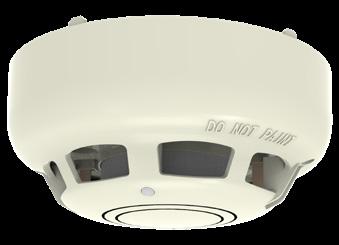
F/CH/ACC-EN Multi-sensor – photoelectric and heat – Ivory

Top Row: F/CH/CHQ-WS2, F/CH/CHQ-WSB(WHT), F/CH/CHQ-WSB2
Bottom Row: F/CHYBO-BS, F/CH/YBO-BS B2, F/CH/CHQ-AB
Wall Sounder Bases For Above
F/YBO-R/3 RED Mounting sounder base – Red
F/YBO-R/SCI RED Short circuit isolator base – Red
Call Points
F/HCP-E/SCI Addressable call point with SCI – Red
F/HCP-W/SCI Weatherproof addressable call point with SCI – Red
F/CH/PS200 Call point cover
Modules & Controllers
F/CHQ-DSC2/SCI Dual sounder controller with SCI
F/CHQ-DZM/SCI Dual zone monitor with SCI
F/CHQ-MRC2/SCI Mains relay controller with SCI
F/CHQ-SZM2/SCI Single zone monitor with SCI
F/CHQ-SIM Single input module
F/CHQ-POM Powered output module
Accessories
F/CHQ-ADAPTER Adapter for new CHQ modules
F/SR/MOUNTING Surface mounting box – Red
F/TCH-B200 ESP programmer & PL-3 lead
Overview
The new collection of SOTERIA® addressable fire detectors are the next generation in fire recognition technology. Powered by CoreProtocol® – Apollo’s fire loop communication protocol – SOTERIA® enhances detection, reduces false alarms and improves reliability. SOTERIA® detectors are user-programmable and can be set to a sensitivity mode best suited for the application. This provides total reassurance in installations where adaptability to changing conditions is paramount. By applying the latest developments in electronics, Apollo’s SOTERIA® detector range meets the demand for ever-more sophisticated alarm systems. These detectors have been designed for use in commercial, industrial, financial, government, IT/telecoms and healthcare sectors, where there is a demand for integration with Building Management Systems (BMS) and more sophisticated functionality.
Features
Currently covering heat and optical detection areas – either individually or in innovative combinations – the exclusive technology incorporated into the Soteria range offers an unrivalled host of benefits, including:
• Enhanced reliability of smoke detection
• Reduction in false alarms
• PureLight® technology
Soteria Level Detectors with Isolator
F/SA5100-600APO Soteria Optical Smoke Detector with Isolator
F/SA5100-400APO Soteria Heat Detector with Isolator
• Simple installation with a new easy-fit base and an isolator located in the head.
• A sleek and stylish low profile design
• Compatible with XP95 & Discovery protocols
• Comprehensively tested to exceed EN54 standards
• Extensively tested at Apollo’s state of the art in-house testing facilities
F/SA5100-700APO Soteria Optical/Heat Multisensor Detector without Isolator
F/SA5100-810APO Soteria Tri-Sensor Detector (Dual Optical/Heat/CO)
Soteria Level Detectors without Isolator
F/SA5000-600APO Soteria Optical Smoke Detector without Isolator
F/SA5000-400APO Soteria Heat Detector without Isolator
F/SA5000-700APO Soteria Optical/Heat Multisensor Detector without Isolator
F/SA5000-200APO Xpert8 Intelligent Mounting Base
FL5100-600APO
Measurements
140mm Diameter x 71mm Depth (with Backbox)
FL5100-600APO
Measurements
170mm Diameter x 71mm Depth (with Backbox)
Dimension Backbox
FL5100-600APO
Measurements 113mm x 71mm Depth
Optical Smoke Detector
SA5000-600 (Non Isolated)
SA500-600 (Isolated)
Measurements 100mm Diameter x 36mm Height
Heat Backbox
SA5000-400 (Non Isolated)
SA5100-400 (Isolated)
Measurements
100mm x 38.5mm Height
Optical/Heat Backbox
SA5000-700 (Non Isolated)
SA500-700 (Isolated)
Measurements
100mm x 38.5mm Height
Xpert 8 Intelligent
Mounting Base
SA5000-200
XPERT 8 Card
38532-064
Measurements 100mm x 12mm Depth
Overview
The ultra low profile smoke detector. The innovative design of the Soteria Dimension Optical Detector differs from standard fire detectors, having no chamber and being flush mounted. A new optical sensing technology is used to detect smoke particles outside the detector housing. A combination of Infra-Red (IR) LEDs and photo-diodes identify smoke particles, detected just below the detector housing and initiates an alarm. Soteria Dimension Optical Detector is designed to be flush mounted, with a very low profile, only 4.55mm below the ceiling. The Soteria Dimension Specialist Optical Detector is independently certified to DHF TS001 for anti-ligature use in specialist areas.
Features
• Comprehensively tested to exceed EN 54–7 standard
• With the intelligence of CoreProtocol
• Backwards compatible with XP95 and Discovery systems
• Unique chamberless fire detection technology
• Intelligent sensing of foreign and transient objects to reduce false alarms
• Integrated Switchable Isolator as standard
• Virtual chamber eliminates dust and insect ingress
• External light rejection
• Drift compensation
• Tri-Coloured LED status indicator
• Custom finishes available
Operation
The Soteria Dimension Optical Detector contains two daylight filtered photo-diodes and three IR emitters in different positions and angles. Different combinations of these are used to act as smoke sensors and proximity sensors to measure the smoke level at the detector and to detect any physical oBS truction or interference of the detector.
F/FL5100-600APO Soteria Dimension Optical Detector
F/FL6100-600APO Soteria Dimension Specialist Optical Detector
F/FL5000-200APO Soteria Dimension Mounting Box
Overview
With 240 devices across a maximum of 100 zones, the Zerio Plus system offers the perfect solution for small domestic buildings up to large commercial premises. System programming. Each device is programmed onto the system using a simple user friendly menu.
Each device is logged on to the system using a wireless link.
Location descriptions can be added by using a PC or simply programmed using a standard PC keyboard plugged into the panel or for a single device the in-built keypad. With analogue detector functionality and complex multi-path fault tolerant signalling, the system minimizes false alarms whilst providing maximum protection for the occupants of a building. In order to ensure wireless coverage either wired or radio booster panels can be installed at appropriate positions. During the automatic set-up the system will configure this equipment to ensure the most effective operation is achieved.
The system complies in full with EN54 Part 25.
Features
• EN54 Compliant
• 240 Fully addressable devices
• Sophisticated cause and effects
• In-built HMO options
• Plugable memory module for back-up
• USB keyboard to program
• Intuitive menu structure
• Configuration reporting via USB memory stick
• 5 access levels
• Compatible with full range of Zerio Plus devices
• Simple to set-up
Typical Applications
• Large office blocks
• Hotels
• Small shops
• Restaurants


F/EDA-D6000
F/EDA-R6000

F/EDA-T6080
Panels
F/EDA-R06030
F/EDA-T5100
F/EDA-D6030 – White
F/EDA-D6030 – Ivory
F/EDA-Z5008 8 zone Zerio Plus control panel (requires 1x 12/7 battery – listed to right)
F/EDA-Z5020 20 zone Zerio Plus control panel (requires 1x 12/7 battery – listed to right)
F/EDA-Z5100 100zone Zerio Plus control panel (requires 1x 12/7 battery – listed to right)
Devices
F/EDA-R5000 Zerio Plus optical smoke detector
F/EDA-R6000 Zerio Plus optical smoke detector complete with sounder
F/EDA-R6030 Zerio Plus optical smoke detector complete with sounder visual indicator
F/EDA-D6000 Zerio Plus heat detector complete with sounder
F/EDA-D5000 Zerio Plus heat detector
Call Point
F/EDA-C5000 Zerio Plus call point
F/EDA-Q585 Call Point Cover
Sounders & Visual Indicators
F/EDA-A6000 Zerio Plus radio sounder
F/EDA-A6060 Zerio Plus radio beacon
F/EDA-A6030 Zerio Plus Radio sounder C/W LED beacon
F/EDA-R6030 Zerio Plus optical smoke detector radio beacon C/W LED beacon
F/EDA-Z6000 & F/EDA-Y5000
Interface Units
F/EDA-T6080 Zerio Plus radio clean contact input/output unit
F/EDA-A6040 Output only unit (Contacts rated at 30d DC 1A)
F/EDA-A6041 Input/Output unit (Contacts rated at 30d DC 1A)
F/EDA-Z6011 Wireless interface for networked systems
Boosters & Aerials
F/EDA-Z6000 Zerio Plus booster panel (requires 240v Supply and 1x 12/7 battery)
F/EDA-Z6010 Zerio Plus hard wired booster panel
F/EDA-Y5000 High gain antenna for use with Zerio Plus
Accessories
F/EDA-Z5000 Zerio Plus survey kit
Batteries
B/12V/7AH/SLA 12 Volt 7Ah sealed lead acid battery (1 block)
S/BATT/EDA-Q690 Replacement batteries for detectors

Overview
REACH is a hybrid wireless solution, enabling units to be connected to our hard-wired loop systems via a loopinterface, just like any other device. This makes REACH ideally suited to buildings and structures with restricted or complex access and installation conditions - such as listed buildings, out-buildings, temporary structures and limited downtime sites such as offices.
Detectors are often installed in buildings where wiring presents a challenge. This could be because the fabric of the building or its design will be negatively affected by the use of cables. It is sometimes very difficult to introduce cable runs into buildings which were not designed for the modern age. It is for these architecturally sensitive buildings that REACH has been developed.
REACH is a system in which individual detectors, call points and alarm devices communicate with the XP95 loop by radio signals. An interface is connected to the loop in the same way as any other interface, such as an input/ output unit.
Every REACH device is assigned an address and this address is recognised by the control panel in the same way as is the address of any device connected directly to the loop wiring.
The REACH range consists of:
• Loop interface module (Max 32 devices)
• Optical smoke detector
• Heat detector
• Multi detector (optical/heat)
• Manual call point
• Sounder base
• Sounder VAD bases
• Open area Sounders
• Open area sounder/VADs
• Input module
• Output module
• Remote Indicator
• Survey kit
The inclusion of alarm devices such as the sounder/VADs help make REACH systems compliant with the Disability Discrimination Act.
Features
• Easy to install
• Soft addressing
• Self-monitoring
• Proven technology
• No special control panel needed
• 868MHz radio channels
• Up to 32 devices per interface
• Up to 10 interfaces per loop (panel dependent)
• Analogue addressable system expansion
• Wireless
• Eliminates cabling difficulties
• Minimises building disruption
• Enables rapid retro-fit
• Preserves aesthetics
• All detectors within the REACH range are sold with mounting bases

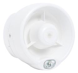
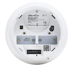
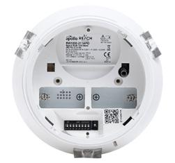
F/RW1000-600APO REACH Optical Smoke Detector
F/RW1000-400APO REACH Heat Detector
F/RW1000-700APO REACH Multi-Sensor Detector (Optical/Heat)
F/RW1500-210APO REACH Open-Area Sounder VAD Cat. W – White Body (White-Flash) (W-2.5-7)
F/RW1500-220APO REACH Open-Area Sounder VAD Cat. W – Red Body (White Flash) (W-2.5-7)
F/RW1300-110APO REACH Sounder Base
F/RW1300-210APO REACH Sounder VAD Base (White Flash) (C-3-15)
F/RW1300-211APO REACH Sounder VAD Base (Red Flash) (C-3-10)
F/RW1500-110APO REACH Open-Area Sounder – White Body
F/RW1500-120APO REACH Open-Area Sounder – Red Body
F/RW1300-010 REACH AV Base Cap - White
F/RW1300-020 REACH AV Base Cap - Red
F/RW1900-901APO REACH Manual Call Point
F/RW1500-800APO REACH Remote Indicator Module
F/RW1700-030APO REACH XP95 Loop Interface Module
F/RW1700-051APO REACH Input Module
F/RW1700-052APO REACH Output Module
F/RW1800-060APO REACH Survey Kit Lite

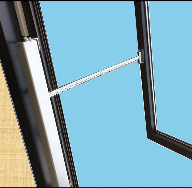
The VESDA range of pipes and fittings have been specially developed to provide fully matched components for the optimal performance of your whole Vesda aspirating system.
They are also manufactured to comply with the requirements of BS 5391 Part 1, EN 61386-1 and the new EN54 Part 20 guaranteeing you quality.
The pipes are a metric standard of 25mm external diameter with suitable adapters available for imperial to metric conversions and are designed for use with any make of low pressure aspirating type smoke detection system.
Unlike some metal pipes, Vesda ABS pipework is very light in weight. This makes it easy to handle in high and difficult places where systems are often installed.
How does Vesda work?
A Vesda detector is much like a vacuum cleaner. It sucks air from the protected environment via purpose built aspirating pipe and fittings and samples the quality of air passing through the Vesda detection laser chamber. Vesda detectors are available in a variety of models to accommodate a broad range of environments and applications. From small to very large, open spaces and from the cleanest to the dirtiest environments, Vesda provides reliable, high-sensitivity, very early warning smoke detection.
Vesda delivers aBS olute protection across a wide range of industries and applications:apartments, Hotels, Shops, Offices (and other accommodation), Correctional Facilities, Clean Rooms, Cold Storage, Hospitals and Health care, Insurance, Nuclear Facilities, Portable Switch Rooms, Power Generation, Records Storage, Transportation, Wind Power Generation & Warehousing.
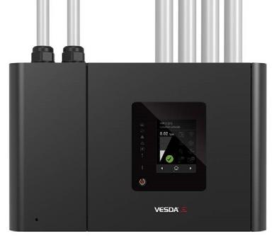
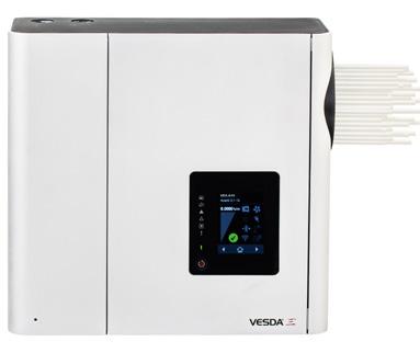
Vesda - VES-A00-P & VES-A10-P
The VESDA-E VES is similar to the flagship VESDA-E VEP aspirating smoke detector but also includes a valve mechanism in the inlet manifold and software to control the airflow from the four Sectors (pipes). This configuration enables a single zone to be divided into four separate sectors, for example, distinguishing between separate aisles within a data room. The VES-A10-P has an LED display while the VES-A10-P benefits from a 3.5” display.
Vesda-E Vea
The VESDA-E VEA series of detectors combine VESDA reliability and early warning smoke detection with pinpoint addressability and a variety of annunciation options that truly surpass traditional spot detectors. VEA uses patented sampling points and multi-channel microbore air-sampling with enhanced or standard alarm sensitivity setting for the sampling points. As a multi-channel addressable system, the VEA detector is able to divide a protected space into sampling locations, enabling the localization of a fire for a faster incident response. VEA is suitable for the protection of area where pinpoint location of fire events is essential, thus providing ideal fire detection solutions for offices, hospitals, schools, prisons, multi-storey dwellings, cabinets in data centres and warehouse racks. A wide range of features provide flexibility, enhanced connectivity and reduced total cost of ownership.
The VEU series of aspirating smoke detectors are the premium detectors of the VESDA-E range. An ultra-wide sensitivity range; 15 times greater than the VESDA VLP, and provision for more sampling holes provide and increased coverage in high airflow applications by at least 40%. Considerably longer linear pipe runs and extended branched pipe network configurations cater perfectly to applications with higher ceilings providing an increased coverage by up to 80% whilst allowing convenient detector mounting for ease of service and maintainance. A range of revolutionary new features provide unsurpassed detection performance, flexibility, field programmability, connectivity and reduced total cost of ownership.
Vesda-E
Vep
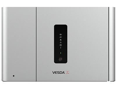
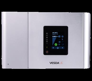
The VESDA-E VEP series of smoke detectors bring the latest and most advanced detection technology to provide very early warning and the best nuisance alarm rejection to a wide range of applications. Built on the Flair detection technology and years of application experience, VEP detectors deliver aBS olute calibration for lifetime performance and a range of revolutionary new features that deliver user value.
Features
• Reliable early detection warning
• Assured performance in challenging environments
• Superior suppression actuation
• Easy & low maintenance
• Reliable detection in large open spaces
• Flexible solution in any facility type
• Wide coverage
• Action before suppression
• Provides time for orderly evacuation
• Avoids risks to precious assets
• Business continuity
• Active air sampling
• Where smoke detection is a challenge
• Tolerant of harsh environments
• Detects smoke in a varied range of conditions and applications
• Prevents nuisance alarms
• Overcomes the effects of smoke dilution
• Security and inmate safety
• Vandalism prevention
• EN 54-20 compliant
Aspirating Equipment
VESDA-E VEA
F/VEA-040-A00
F/VEA-040-A10
VESDA-E VEU
F/VEU-A00
F/VEU-A10
VESDA-E VEP
F/VEP-A00-P
F/VEP-A10-P
VESDA-VES
F/VES-A00-P
F/VES/A00-P
Piping
F/VEA-040-A00
VESDA-E VEA-40 Detector with LEDs. Max pipe length 40 x 100m
VESDA-E VEA-40 Detector with 3.5” Display Max pipe length 40 x 100m
VESDA-E VEU with LED’s. Max pipe length 4 x 100m or 800m with branches
VESDA-E VEU with 3.5” Display. Max pipe length 4 x 100m or 800m with branches
VESDA-E VEP with LEDs, 4 pipe. Max pipe length 4 x 70m or 560m with branches
VESDA-E VEPwith 3.5” Display, 4 pipe. Max pipe length 4 x 70m or 560m with branches
VESDA VES Scanner with LED Display, 4 Pipe, Max pipe length 280m linear or 560m branched (No. of holes dependent)
VESDA VES Scanner with 3.5” Display, 4 pipe, Max pip length 280m linear or 560m branched (No. of holes dependent)
F/CH/PIP-001 1 x 3m length of pipe
Accessories
F/CH/PIP-002 25mm jointing socket
F/CH/PIP-003 25mm socket union-screw tight-unit price (comes in pack x 10)
F/CH/PIP-005 90 degree bend
F/CH/PIP-006 45 degree bend 25mm
F/CH/PIP-007 End cap 25mm
F/CH/PIP-008 T piece 25mm
F/CH/PIP-009 Pipe clip
F/CH/PIP-012 Solvent cement
F/CH/PIP-014 Pipe cutters
F/CH/PIP-015 Flush sample point – head only
F/CH/PIP-016 Trunk adaptor
F/CH/PIP-059-001 Flush sample point assembly
F/CH/PIP-059-007 Conical sampling point
F/CH/PIP-221-035 10mm capillary pipe x 30m
F/CH/PIP-222-059 Discrete end cap
F/CH/VSP-005 Filter for all Vesda detectors
PSU's
F/CH/VPS-215 1.5A PSU – Vesda (requires 2x B/12V/7AH/SLA batteries)
F/CH/VPS-220 2A PSU – Vesda (requires 2x B/12V/12AH/SLA batteries)
Batteries
B/12V/7AH/SLA 12 Volt 7Ah sealed lead acid battery (1 block)
B/12V/12AH/SLA 12 Volt 12Ah sealed lead acid battery (1 block)
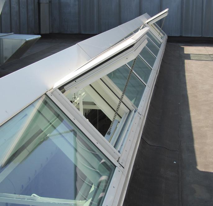
What is an AOV?
AOV is simply an abbreviation for “Automatic Opening Vent”. An AOV system is a control system designed to vent air or smoke for use in natural & smoke ventilation.
So Why Do I Need An AOV System?
AOV control systems are used mainly to control the ventilation of smoke in a fire. Changes to building regulations were made due to the results of investigations into smoke inhalation.
When a detector or call point is triggered an AOV control system will open actuators, windows or vents to create ventilation. This clears smoke for people leaving the building and vents smoke out of the area that has been triggered. The provisional standard that is now available for reference is EN:12101.
Smoke Control Systems are required in multi-storey residential buildings, hotels, student accommodation and principally to protect the stairs to assist escape in the event of a fire, in compliance with the recommendations of Approved Document B and BS 9991:2015.
In multi-storey residential buildings, the main escape route is always via common corridors and/or lobbies into the stairs. That aim is to keep stairs reasonably free of smoke and to improve conditions in corridors and lobbies opening onto the stairs.
How Do I Decide Which AOV System To Fit?
You first need to decide what items you need to control on your system. You should work out how many items will need to open separately & then class each one as a zone. See the following examples:
Example 1:
You have one roof vent or window which must open when the fire alarm is triggered...
In this situation you have 1 zone. You need to first see how the roof vent or window operates. If it is manual opening then you will need to add an AOV actuator which can be triggered to open or close. If there is already a fire system in place there may be smoke detectors fitted. In this situation you can link an AOV single zone to your fire system which will trigger when smoke is detected in that area. The AOV actuator when triggered will open, when reset it will close. Yellow call points can be added for override or system test. (If there is no fire system in place a detector can be fitted to trigger the system.)
Example 2:
You have 4 floors, a window on each, and a vent for a shaft on the roof...
This situation would leave you with 5 zones. Here you would use an AOV multi zone panel which will be able to open/close each zone independently. Under this condition it may be that the vent should open together with any zone that is triggered. (A roof vent will be on a smoke shaft or stairwell. Opening it together with a window will then create a chimney effect clearing smoke.)
In this case you can set the AOV multi zone with zone 1 as a “master”. A simple solution that will then trigger zone 1 together with any of the zones 2–5.
Again you would then need to add an actuator to each window/vent and either link to your existing fire system or add call points & smoke detectors to the AOV multi zone system to trigger.
System Layout & Wiring
The diagram below shows the typical system architecture for a single zone panel system. The AOV can be triggered by an input from a fire alarm system or dedicated smoke detectors.
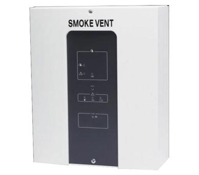
Control Panels
F/SVM/24V-5A/BASIC Smoke control panel 1-zone 24V-5A
F/SVM/24V-8A/BASIC Smoke control panel 1-zone 24V-8A
F/SVL/MULTI/2-6 2-6 Channel AOV control panel 24V
F/SVL/ZC 15A Additional Zone card for above
Chain Drives
F/HCV500/0350 Chain drive 24Vdc, 500N, 350mm
F/HCV500/0600 Chain drive 24Vdc-500N-600mm
F/HCV500/0800 Chain drive 24Vdc, 500N, 800mm
F/HCV500/1000 Chain drive 24Vdc, 500N, 1000mm
F/HCVSS/BKT Bracket for above
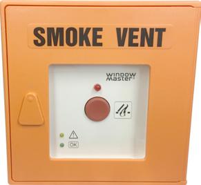
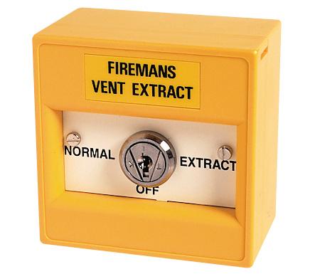
Fireman’s Controls
F/WSK/321/0005/61 Break glass, SVM, orange
F/IMCP Break glass for SVL Multi
Smoke Detectors
F/CHSM/P (55000-317) Optical smoke detector with base
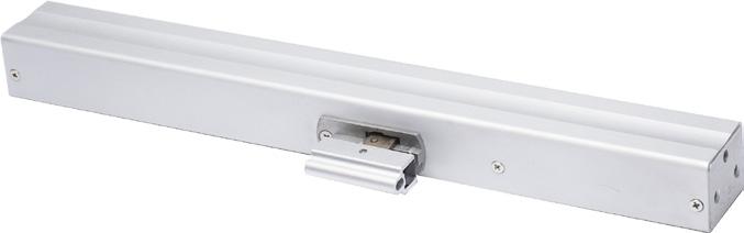
F/HCV500/0350
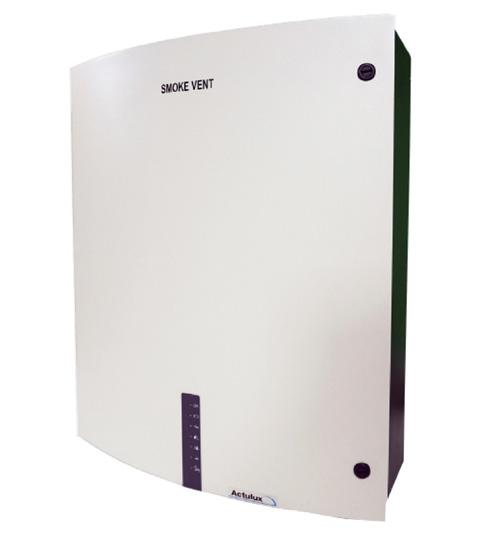
F/SVM/24V-8A/BASIC
1st Floor
Features
The firebeam specialist detection system is reliable and easy to maintain, and more importantly it will reduce the risk of expensive false alarms and misalignment faults. Beam detectors offer a cost effective solution for protecting large open spaces. One single unit installed on a wall can detect smoke over areas far greater than that of traditional point detectors.
Ideal For Protecting Areas Such As:
• Warehouses
• Theatres
• Sport centres
• Places of worship
• Atriums
• Supermarkets
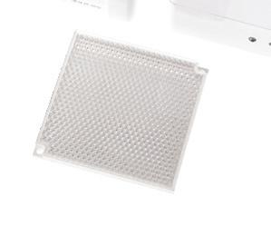
Mid Range Distance Kits (70-140 Metres)
Designed to cover distances between 70 and 140 metres, the Fire Beam Mid Range Kit is a clear acrylic plate with 3 extra reflectors attached.
Long Range Distance Kit (140-160 Metres)
Designed to cover distances between 140 and 160 metres, the Fire Beam Long Range Kit is a clear acrylic plate with 8 extra reflectors attached.
Simply add the single reflector that is provided with the standard Fire Beam into the spare space on the plate using the screws provided. Firebeam is designed to fully comply with EN 54 part 12. and exceeds European standards, in particular BS 5839 part 1.
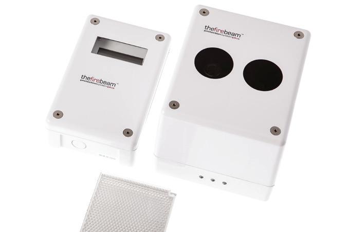
Self Adjusting Beams
F/CHBM/SA/2 Self adjusting beam detector 7 – 70m range
F/CHBM/70/KIT/2 70 – 140m range kit for CHBM/SA/2
F/CHBM/140/KIT/2 140 -160m range kit for CHBM/SA/2
F/CHBM/ADAPTER Unistrut Adapter for CHBM/SA/2
F/PSU24/1.5/BMEN54 Power supply
Anti-Fog Kits
SP/CHBM/70KIT Anti-Fog 70-140m range kit for CHBM/SA/2
SP/CHBM/140/KIT Anti-Fog 140-160m range kit for CHBM/SA/2
Addressable Beam Detectors
F/CHBM/SA/95 SA7100-100 Apollo Self Adjusting Beam 8-50M
F/CHBM/R/95/EXT/KIT 29600-526 50-100M Extension Kit
Distance & Position Guidelines
A roof is considered flat unless the height of the apex is greater then 0.6m. If the roof is fl at fi rebeam system can be placed anywhere under the roof between 0.3m and 0.6m below the roof, up to a maximum height of 40m from the floor. Firebeam has a detection area of 7.5m either side of the beam. If the roof is considered to have an apex, place the firebeam system 0.3m to 0.6m down from the top of the apex, up to a maximum height of 40m from the floor. The maximum protected area either side of the beam can be extended by 1% for every degree of roof pitch, see the example.
You should always position the
at least 0.5m away from any protrusion
Features
The Alarmline cable is designed to detect at fixed temperature along its entire length. Upon operation, the cable gives a short circuit signal which can be linked very simply to your existing fire alarm system. Fully monitored by use of an end of line resistor, Alarmline cable offers detection in areas previously unprotected.
• Environmental -65˚C to +200˚C
• 5 detection temperature ranges from 61˚C to 238˚C
• Simple interface to any BS 5839 system, FM approved
• Fully monitored
• Twin-conductor switching heat sensing cable
• Effective monitoring at precise point of risk
• Economical, reliable and durable detection
• Simple and easy to install
• Applied where other types of fire detection are unsuitable
• Ideal for dirty or harsh environments such as: Escalator pits, Pipe and cable tunnels/trays, Conveyor belts, Petro chemical, Freezers cold rooms, Within racking

Cable
F/AD68-0100 63˚-70˚C Alarmline cable (68˚C nominal) * Supplied in 100m,
500m & 1000m lengths only
F/AD88-0100 79˚-95˚C Alarmline cable (88˚C nominal) * Supplied in 100m, 200m, 500m & 1000m lengths only
F/AD105-0100 101˚-108˚C Alarmline cable (105˚C nominal) * Supplied in 100m, 200m, 500m & 1000m lengths only
F/AD185-0100 177˚-189˚C Alarmine cable (185˚C nominal) * Supplied in 100m, 200m, 500m & 1000m lengths only
Accessories
F/ACAC-CP-025 P clip for use with Alarmline cable – Pack of 25
F/ACA-CT-025 T clip for use with Alarmline cable – Pack of 25
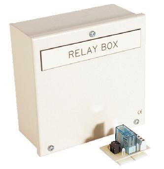
Features
• Our heavy duty relay units are designed for interfacing heavy loads such as door release units or plant shut down equipment with fire alarm systems
Interface Relays
S/E15/A 24V 5A double pole relay
S/E60/A 12Vdc 5A double pole
S/E55/A 230V 5A double pole relay
F/CH/HDR/5 24 V 5A double pole relay in heavy duty box
S/CH/BF376 24V 5A Relay on single gang plate
Please note: The plate is about 1/2 the size of the box in the current picture.
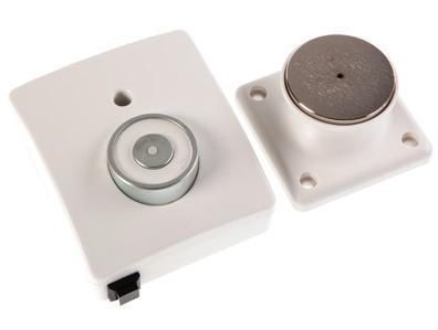
Features
• Reduced installation cost – no mains supply or PSU required
• No batteries to replace
• Complies with BS 7273-4
• Allows phased evacuation
• Fully monitored by the fire alarm control panel
• 200N Holding force
(55000-982)
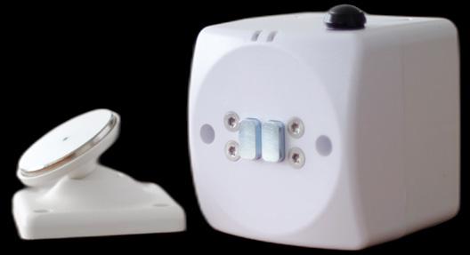
Features
• With a flame retardant, low profile ABS plastic body, installation is made simple, with knockouts provided for entry of surface mount conduit, there is ample room to connect external wiring to the 4.0mm terminals. Each door retainer is fitted with a spring loaded release pin mounted centrally within the electro-magnet. On power off, the release pin then ensures that the fire door is pushed away from the electro-magnet.
• Additional accessories are available, including floor brackets, chains and additional keeper plates
• Flame retardant, low profile ABS plastic body
• All door retainers are designed to comply to the latest requirements of EN 61000-3-2, EN 50081-1, EN 60950 and EN 1155


F/CHDR/24 24V magnetic door release
F/CHDR/240 240V magnetic door release
F/CHDR/BK Door release mounting bracket
F/CHDR/CHAIN 1m chain for magnetic door release plates
Features
• 27V DC nominal output
• Remote control of output
• Choice of switching options: Closing of normally open contact
• Application of an external 24V DC supply
• LED Indication: mains status/output fuse failure
• Mains transient protection
• Fail safe operation
Alarmline Cable
Typical Applications
• Opening of a normally closed volt-free contact
• Closing of a normally open volt-free contact
• Application of an external 24V DC supply such as a sounder circuit
F/CHDR/PSU/2 PSU 24V 2A in enclosure
F/CHDR/PSU/4 PSU 24V 4A
Features
• Unique ‘Plug & Go’ installation concept
• Total ‘Flex-Ability’ in the choice of operating element
• Anti-Tamper facility
• Enhanced aesthetics
• Backward compatibility
• Proven design approved and certified to EN54-11
• Use of glass or resettable plastic element
• Alarm indicator and 240v changeover contacts
• Back box with fixing screws
F/CH/PC
F/CH/EDR/FLEX
F/CH/ER
Overview
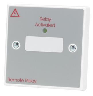
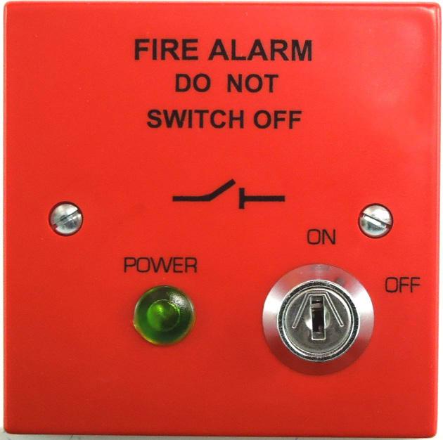
This product provides a secure method for safely isolating the mains voltage supply to fire systems in accordance with BS 5839: Part 1 (2002).
Features
• Both the Live and Neutral supply is switched
• Integral fuse, which cannot be removed without taking the cover off
• The supply can only be isolated by means of a keylock switch
• The key is removable in both ON/OFF positions
• A Green LED is used to indicate mains present at the switched outputs
Fire Alarm Switched Fused Spur
F/CHFA/SFS Key operated double pole switched fused spur
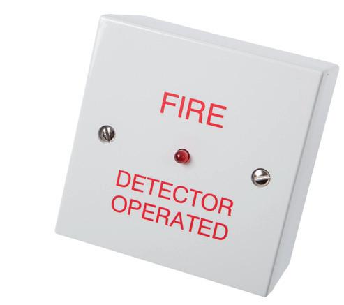
Features
• Used to show operation of hidden smoke detectors
• Supply voltage range – 5-28Vdc
• IP Rating – F/CHRI/60 – IP 42 & F/CHRI/AS – IP66
• Current – 24mA
• Weight – F/CHRI/60 – 38g & F/CHRI/AS – 117g
• It can be used to link into either addressable, conventional, 2-wire & 4-wire fire detection system arrangements
Remote Indicators
F/CHRI/60 Remote indicator
F/CHRI/AS AlarmSense remote indicator (round)
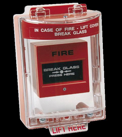
Call Point Cover Features
• Constructed from tough clear polycarbonate
• Easy to install, can retrofit over existing devices
• Includes integral sounder, powered by a 9V PP3 battery (included)
• Protects equipment from accidental operation, vandalism, product misuse, dust and weather
• Flush and surface mounted versions available
Key Point Cover Features
• Sturdy ABS plastic key holder secures and provides visible storage of emergency keys
• Supplied with printed glass (perspex) that reads “BREAK GLASS FOR KEY”
• Constructed from robust ABS plastic casing with a crystal styrene window to protect your emergency keys until needed
Call Point & Key Point Covers
Call Point Cover
F/CHBGC/KIT Heavy duty flush and surface Break Glass Cover Kit
F/CHBGC/KIT/S Heavy duty flush and surface Break Glass Cover Kit with Sounder
Accessories
F/CHSG 10 pack spare glass
Key Point Cover
F/KEY BOX Break glass key box
F/KEY BOX GLASS Spare glass for key box

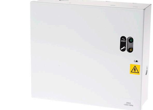
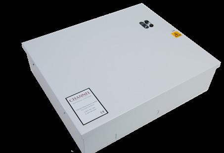
Overview
We supply a high efficiency, cost effective range of switch mode power supplies featuring mains and battery monitoring. The modular construction enables easy maintenance and upgrade capability.
Encapsulated units are class II double insulated.
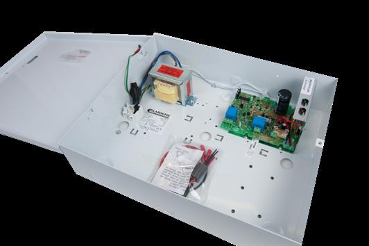
EN54 Compliant 1.5A PSU Features
• 24V 1.5A EN54-4/A2 Boxed PSU
• VdS certified to EN54-4/A2
• Batteries: 2x 12V Min. 2Ah, Max. 3.4Ah
• 380 x 235 x 96mm plastic enclosure
EN54 Compliant 1.5A PSU Features
• 24V 3A EN54-4/A2 Boxed PSU
• LPCB certified to EN54-4/A2
• Batteries: 2x 12V Min. 7Ah, Max. 12Ah
• 404 x 404 x 110mm metal enclosure
Non EN54 Compliant Power Supply Units
F/PSU/12/1/BM 12V 1A power supply unit – battery monitored (Max. 1x B/12V/7AH/SLA)
F/PSU/12/2/BM 12V 2A power supply unit – battery monitored (Max. 1x B/12V/7AH/SLA)
F/PSU/12/3/BM 12V 3A power supply unit – battery monitored (Max. 1x B/12V/7AH/SLA)
F/PSU/12/5/BM 12V 5A power supply unit – battery monitored (Max. 1x B/12V/7AH/SLA)
F/PSU/24/1/BM 24V 1A power supply unit – battery monitored (Max. 2x B/12V/7AH/SLA)
F/PSU/24/2/BM 24V 2A power supply unit – battery monitored (Max. 2x B/12V/7AH/SLA)
F/PSU/24/3/BM 24V 3A power supply unit – battery monitored (Max. 2x B/12V/7AH/SLA)
F/PSU/24/5/BM 24V 5A power supply unit – battery monitored (Max. 2x B/12V/7AH/SLA)
EN54 Compliant Power Supply Units
F/PSU24/1.5/BMEN54 EN54 compliant 24V 1.5A power supply unit – battery monitored (Min. 2x B/12V/3.2AH/SLA – 12V 3.2AH)
F/PSU24/3/EN54/1 EN54 compliant 24V 3A power supply unit – battery monitored (Min. 2x B/12V/12AH/SLA – 12V 12AH)
Batteries
B/12V/2.1AH/SLA 12 Volt 2.1Ah sealed lead acid battery (1 block)
B/12V/2.3AH/SLA 12 Volt 2.3Ah sealed lead acid battery (1 block)
B/12V/2.8AH/SLA 12 Volt 2.8Ah sealed lead acid battery (1 block)
B/12V/7AH/SLA 12 Volt 7Ah sealed lead acid battery (1 block)
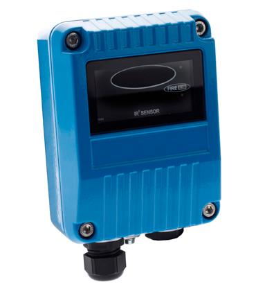
Overview
Talentum® is perfect for environments and industries where steam, smoke and dust are commonplace.
Using infra-red (IR) sensing technology flames can be detected through such elements as dust, steam and smoke; they are also immune to the effects of wind or draughts of air. With the addition of an ultra-violet (UV) sensor a flame detector becomes highly immune to false signals such as sunlight. The optical sensors within the detector receive the IR and/or UV radiation emitted by the flames. The processor within the detector analyses the optical sensor signal waveforms and determines if they represent flames and if so accepts them. If the signals do not match the internal algorithms for flames then they are considered to be false sources and rejected.
Features
• Available for indoor and outdoor areas
• Flame-proof, explosion-proof and high ambient temperature options
• Internal self-test capability giving the highest immunity to false-flame sources
• Detects invisible flames from fuels such as Hydrogen and other inorganic fuels
• Immune to the effects of wind, draughts and sunlight
Where Talentum® Performs
Agriculture | Automotive | Aircraft Hangers | Aeronautical Repair | Bed Fillings | Biomass Storage & Handling | Chemical Plants | Coal Racks | Generators | High Voltage Equipment | LNG/LPG Production | Military & Marine | Nuclear and Non-Nuclear Power Plants | Petrochemical | Pharmaceutical Production | Printing | Refineries | Spray Booths | Storage Tanks | Tunnels | Waste Recycling | Woodworking
F/FFE-16581
F/FFE-16571
F/FFE-16511
F/FFE-16589
F/FFE-16579
F/FFE-16519
F/FFE-16591
F/FFE-16521
Talentum Dual IR. High immunity to flase sources. Suitable for indoor areas only
Talentum Dual IR. Intrinsically safe (IS) for hazardous areas. High immunity to false sources. Suitable for indoor areas only
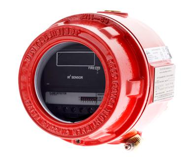
Talentum Dual IR. Flameproof (Exd) for hazardous areas. High immunity to false sources. Suitable for indoor areas only
Talentum Triple IR. Excellent immunity to false sources. Suitable for indoor or outdoor areas.
Talentum Triple IS IR, Intrinsically Safe (IS) for hazardous area excellent immunity to false sources. Suitable for indoor or outdoor areas.
Talentum Triple IR, Flameproof (Exd) for hazardous areas. Excellent immunity to false sources. Suitable for indoor or outdoor areas.
Talentum UV/IR2. Highest immunity to false sources.
Suitable for indoor or outdoor areas.
Talentum UV/IR2 Flame Detector. Flameproof (ExD). Highest immunity to false sources. Suitable for indoor or outdoor areas.
Fire detector test and service equipment must be safe both for engineer and system. As a minimum it must comply with international codes and standards and be approved/endorsed by detector manufacturers and third party listing agencies but it also needs to be cost-effective, portable and versatile.
The Solo range meets and exceeds all of these requirements and more!
Functional checking is accomplished by introducing a smoke, or simulated smoke, stimulus from the protected area through the vents of a detector to the sensor(s). It is required by all national standards around the world and testing by electronic means that do not involve this test is not sufficient to comply.
Functional checking of heat detectors, with a genuine heat source, is now required by major national standards around the world. Testing with heat sources not designed for the purpose can be both dangerous and damaging. The Solo range of heat detector testing equipment is designed specifically for purpose and provides a professional solution.
Many multi-sensor fire detectors detect carbon monoxide (CO) as well as smoke and/or heat. Under international codes and standards the CO cell needs to be functionally tested with a CO stimulus from the protected area through the detector vents to the sensor.
Solo CO – used in conjunction with Solo 330/332 dispensers – provides a safe way of achieving this with CO concentration levels high enough to activate an alarm, but low enough not to pose danger to user health.
Detectors need removal and replacement for various reasons. The vast majority are fitted on bayonet mountings and the task can be done using specialist tools fitted to appropriate access poles. Using such specialist devices saves the time, cost, disruption and risk to safety that ladders, scaffolding or access gear represents. Faced with a vast array of different models shapes and sizes the professional needs a universal tool. Compatible with an astonishingly wide range of detectors, the colour-coded heads of the Solo 200 rotate to provide a combination of sizes and settings for just about every detector.
Solo Telescopic Poles are required for detectors out of normal reach. Their use saves the time, cost, disruption and risk to safety that ladders, scaffolding or access gear represents.
The contents of each Testing Kit are determined according to your individual testing needs – see the next page for our Kit Selector and Product Range Selector to help you choose the solution right for you.
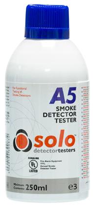
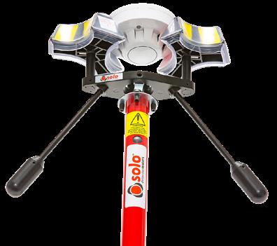
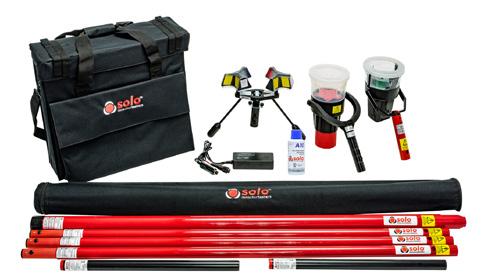
Kit Selector
F/CH/SOLO/808
F/CH/SOLO/809
Solo A5 Smoke Detector Tester Aerosol
F/CH/SOLO/808
F/CH/SOLO/809
(x2)
F/CH/SOLO/822
Solo Detector Testing
Channel Economy Option For Detector Testing
F/CH/SMOKESABRE-01-001 Handheld spray for generic detector testing 150ml
Solo Smoke Testing
F/CH/SOLO/330 Smoke dispenser
F/CH/SOLOA5 Solo test smoke aerosol 250ml
Solo Heat Testing
F/CH/SOLO/423 Mains heat tester (110V)
F/CH/SOLO/424 Mains heat tester (220V)
F/CH/SOLO/461 Cordless heat tester kit
F/CH/SOLO/460 Cordless heat tester (head unit only)
Solo CO Testing
F/CH/SOLO/CO Solo CO fire detector tester aerosol
Solo Removal & Cleaning
F/CH/SOLO/200 Removal tool
Solo Telescopic Poles
F/CH/SOLO/100 Telescopic pole (6m reach)
F/CH/SOLO/101 Extension pole (1.13m length)
F/CH/SOLO/108 Telescopic pole (3.5m reach)
Solo Accessories
F/CH/SOLO/610 Carrybag (including pole bag)
Solo Testing Kits
F/CH/SOLO/811 Smoke kit 6m for testing and removing
F/CH/SOLO/812 Smoke kit 8.2m for testing and removing
F/CH/SOLO/814 Smoke/mains heat kit 6m for testing
F/CH/SOLO/822 Cordless – Smoke/heat kit 6m for testing
F/CH/SOLO/823 Cordless – Smoke/heat kit 9m for testing

Fire Detection & Fire Alarm Systems for Buildings
The Regulatory Reform (Fire Safety) Order (FSO) Became Law On 1 October 2006
Legally You Must Comply! What Is The FSO?
Fire authorities no longer issue fire certificates and those previously in force now have no legal status. The Regulatory Reform (Fire Safety) Order (FSO) replaced most fire safety legislation with one new Order.
It means that any person who has some level of control in premises (normally the employer) must take steps to reduce the risk from fire, consider how to contain a fire should one break out and then also make sure people can safely escape if there is a fire.
• All fire alarm designs should be based on an assessment of the risk
• All Fire Risk Assessments should be carried out by a competent person
• Fire Risk assessments must be reviewed regularly
What Constitutes a Fire Risk Assessment and Its Outcome?
• Identifying fire hazards such as sources of ignition, fuel or oxygen
• Identifying all people at risk in and around the premises
• Evaluating the risk of a fire starting and the risk to people from a fire
• Removing or reducing fire hazards or risks to people from a fire
• Protecting people by providing fire precautions
• Recording the significant findings
• Preparing an emergency plan
• Informing and instructing any relevant people, including visitors
• Providing training for staff
• Reviewing the fire risk assessment regularly and make changes where necessary
• Keeping accurate fire risk assessment records
Where Does The Order Apply?
Virtually all premises and nearly every type of building structure and certain open spaces.
If you would like to find out more about how Apollo products can help you comply with the FSO please contact us on 023 9249 2412 or visit our weBS ite on www.apollo-fire.co.uk
This guide is intended to be an aid to designers and dnstallers of Fire Detection Systems. It is not to be used as a suBS titute for BS 5839-1 which should be read in full. In order to help identify the relevant sections, each diagram includes a reference to BS 5839-1
Designer Responsibilities
Notes:
(1) BS 5839-1 recommends that a fire detection system is designed by a competent person, who takes responsibility for completing the design and signing off a ‘Design certificate’. This should not be confused with other certificates relating to Installation.
(2) If the contract allows, it is suggested that the Designer witnesses testing of the completed system to ensure the original design is still appropriate; the Design certificate can then be completed after any amendments are included.
The following recommendations should be followed when designing a fire detection system:
• Establish the level of fire protection suitable to the premises type in agreement with the owner/occupier and relevant interested parties
• Document any reasons to justify variation of design
• Identify detection and alarm zones
• Raise specification document and building plan to show location of:
- All manual call points
- All types of detector
- All sounders and visual alarms
- Any other items of detection
• Cable specification for each circuit
• State the System and equipment to be used
• Details of other equipment that may be linked into the system to be specified
• Measures incorporated to limit false alarms
• Provide a fire plan or cause and effect chart
• Design certificate signed
• Fire Risk assessments must be reviewed regularly
Fire Alarm and Detection Systems are categorised in the following way:
Property Protection Fire Systems
P AFD designed primarily to protect property
P1 AFD installed throughout all areas
P2 AFD installed only in defined areas
Life Protection Fire Systems
L AFD designed to primarily protect human life
L1
L2
L3
L4
L5
AFD installed throughout all areas
AFD installed in defined areas in addition to L3
AFD installed in escape routes and rooms or areas opening onto these routes
AFD installed in escape routes comprising circulation area and spaces such as corridors and stairways
A non-prescriptive system in which protected area(s) and/or the location of detectors is designed to satisfy a specific fire risk objective (other than that of L1 to L4)
M System design to be operated manually (no AFD)
AFD - Automatic Fire Detection
A detection zone should cover no more than 1 storey, unless total floor area is less than 300m2. Voids in the same fire compartment should be included in the same floor zone. The maximum floor area of a zone should not be greater than 2,000m2, except for some large open plan areas that incorporate manual call points only, which can be extended to 10,000m2.
The maximum search distance for the fire fighters to see the seat of the fire within a zone should not exceed 60m assuming the route taken is the worst possible option. Vertical structures like stairwells, lift shafts etc., should be considered as separate zones.
A manual call point within a staircase should be connected to the zone associated with that floor and ideally be mounted on the accommodation side of the corridor exit. Automatic sensors on the stairwell remain as part of the stairwell detection zone.
An alarm zone is clearly defined within the standard but generally is an area of the building coinciding with the fire compartment boundaries. There must be a clear break between these alarm zones to ensure alert and evacuation messages are not overheard from adjacent areas.
The only other criteria is that an alarm zone may consist of a number of detection zones but not vice versa.
Alarm zones are required when phased or staged evacuation is required. It is therefore important that care should be taken to ensure only one message is heard at any one time particularly where two alarm zones are attached.
Section 2
Clause 13.2.3
The sensing element of a smoke detection device (optical smoke or ionisation chamber) should not be less than 25mm below ceiling, and not greater than 600mm below ceiling.
Clause 22.3
The sensing element of a smoke detection device (optical smoke or ionisation chamber) should not be less than 25mm below ceiling, and not greater than 600mm below ceiling.
X X <25mm
detector
The sensing element of a heat detection device should not be less than 25mm below ceiling, and not greater than 150mm below ceiling.
Clause 35.2.3
The minimum static response to heat devices should not be less than 29°C above the average ambient temperature, or less than 4°C above the highest temperature the device can expect to experience.
Clause 22.3
When mounted on a flat ceiling, smoke detection devices have an individual coverage of 7.5m radius. However these radii must overlap to ensure there are no ‘blind spots’. Therefore individual coverage can be represented by a square measuring 10.6m x 10.6m giving an actual area coverage of 112m2 per device.
When mounted on a flat ceiling, heat detection devices have an individual coverage of 5.3m radius. However these radii must overlap to ensure there are no ‘blind spots’. Therefore individual coverage can be represented by a square measuring 7.5m x 7.5m giving an actual area coverage of 56.3m2 per device.
Treat as a flat ceiling Ceiling with an apex
For ceilings that feature an apex: as long as the height of the apex from the rest of the ceiling is less than 150mm for heat detectors or less than 600mm for smoke detectors, then these can be treated the same as flat ceilings. For higher apexes, a device should be installed at the highest point. The distance to adjacent devices can be increased by 1% per degree of angle of the roof up to a maximum of 25%.
In corridors less than 2m wide the horizontal spacing of detectors may be increased, the areas of coverage need not overlap as in the case of a room. Any corridor over 2m wide is deemed a room and device spacing should follow the standard for rooms.
Do not site detectors less than 1m from air supply points or air conditioning units.
A device should not be mounted within 500mm of any oBS truction. If the top of a solid partition is less than 300mm from ceiling then treat it as a wall. Similarly, ceiling oBS tructions such as beams should be treated as walls if deeper than 10% of the ceiling height.
Never mount devices closer than twice the depth of light fittings or other oBS tructions on the ceiling.
Voids less than 800mm in height need not have independent coverage, unless fire or smoke is able to spread from one area to another through the void or risk assessment shows AFD (Automatic Fire Detection) to be necessary. 1.5m
Vertical shafts like lifts and open stairways should have a device mounted within 1.5m of any opening. (This is not necessary for enclosed stairways, because as noted below, there are detectors on every landing within the stairway).
Enclosed stairways should have a detector at the top of the stairway and on each main landing.
Clause 20.2
Route to travel 30m max. (undefined) at design stage
Route to travel 45m max. (defined) at design stage
A person should not have to travel more than 45m to reach a Manual Call Point, for a defined escape route (25m if significant proportion of occupants have limited mobility or rapid fire development is likely).
For an undefined route a person should not have to travel more than 30m to reach a Manual Call Point (16m if significant proportion of occupants have limited mobility or rapid fire development is likely).
1.4m (+/–300mm)
The centre of the element of the manual call point should be positioned 1.4m (+/-300mm) from floor level. Unless a wheelchair user is likely to be the first person to raise the alarm. (Between 800-1200mm according to Doc. M. + Equality Act). BS 5839 states transparent hinged covers should be fitted to all manual call points.
Clause 16.2.1
The minimum sound level should be 65dB(A) or 5dB(A) above a background noise which is louder than 60dB(A) (if lasting more than 30 seconds) and at a frequency of between 500Hz and 1000Hz. The maximum sound level should not be greater than 120dB(A) at any normally accessible point. May be reduced to 60dB(A) in stairways, enclosures up to 60m2 and specific points of limited extent.
Clause 17
Sounder device cabling should be arranged so that in the event of a fault at least one sounder will remain operational during a fire condition.
The coverage volume code is presented as W-x-y.
If the wall mounted Visual Alarm Device (VAD) is installed at the height of 2.5m from floor level, and the coverage is 7m x 7m square, then it would be referred to as W-2.5-7.
For areas where people are sleeping, sounder devices should produce a minimum 75dB(A) at the bed-head with all doors shut. In buildings providing sleeping accommodation for deaf or people with impaired hearing, bedrooms should have both audible and visual alarms. (Note: Visual Alarm Devices are not intended to wake sleeping persons).
The coverage volume code is presented as C-x-y.
If the ceiling mounted Visual Alarm Device (VAD) is installed at the height of 3m from floor level, and the coverage diameter is 8.5m, then it would be referred to as C-3-8.5.
Clause 26
Mains supply
Fire resistant cabling is now required within the whole fire alarm system including the mains supply cables. The use of non-fire resisting cables whether mechanically protected by fire-resisting construction or not, will no longer comply with BS 5839-1.
Clause 12.2.2
Decibel loss occurs through doors: approximately –20dB(A) through a normal door, and approximately –30dB(A) through a fire door. Unless a sounder is installed in a bedroom, it is unlikely that 75dB(A) will be achieved.
Short circuit isolators limit the effect of one fault to 2000m2 and to a single storey of the building. ‘2 simultaneous faults on a circuit should not disable protection within an
Clause 16.2.1
Suitable means of local safe isolation of the low voltage supply circuit for the power supply and control equipment must be provided (see Section 2 Clause 25.2c & f).
All cables to be fire resistant with a minimum cross-sectional area of 1mm² (see Section 2 Clause 26.2j).
All joints ‘other than those within the system components’ to be fire resistant. Junction boxes to be labelled ‘FIRE ALARM’ (see Section 2 Clause 26.2g).
Enhanced cable to be used where more than 4 zones of phased evacuation required, in multi storey systems, hospitals (un-sprinklered over 30m) or risk assessment requires enhanced cable (see Section 2 Clause 26.2c).
Cable using trunking as a means of containment must be clipped using fire resistant supports WITHIN THE TRUNKING (see Section 2 Clause 26.2h).
Fire Alarm control panel(s) are installed at a location appropriate for staff and firefighters (see Section 2 Clause 23.2).
Manual call points are required at all exits to the open air – whether or not the exits are specifically designed to be fire exits unless, for example, the exits lead to an enclosed courtyard from which there is no escape (see Section 2 Clause 20.2c).
CO fire detectors should be spaced as per smoke detectors, but cannot be used without smoke detectors on escape routes (see Section 2 Clause 22.4).
Multi-sensors, incorporating smoke detection should be spaced as smoke detectors, if used as individual types, for example heat in the day & smoke at night then detectors are spaced in this case as per heat detectors (see Section 2 Clause 21.1.6).
Linear heat detection cable should be spaced as a point heat detector (see Section 2 Clause 22.3).
Unusual ceilings: Cellular ceiling, perforated ceilings or ceilings with closely spaced beams have special spacing & installation requirements (see Section 2 Clause 22.3 including Tables 1 & 2).
Bells and Electronic Sounders cannot be mixed (see Section 2 Clause 16.2.1c).
Sound levels can be reduced to 60dB(A) in stairs, small cellular rooms or enclosures of no more than APPROXIMATELY 60m2. Bedhead levels remains 75dB(A) (see Section 2 Clause 16.2.1a).
Where applicable, all areas of the building have been fitted with Sounders and Visual Alarm/Tactile Devices in areas of high ambient noise, or where deaf people or people with impaired hearing may be alone or isolated from others i.e. bedrooms and sanitary facilities (see Sections 2 Clause 17 & 18).
A minimum of one sounder is required in each fire compartment (see Section 2 Clause 16.2.1i).
Full documentation required, test results as fitted drawings etc. (see Section 5 Clause 40).
An installation certificate will be required (Section 5 Clause 41.2).
Ensure that the installation wiring complies with the BS 5839-1 requirements and the latest edition of the IET Electrical Regulations If an insulation resistance test is carried out, ensure that the field devices are disconnected. Make sure that the loop cables are grounded before field devices are reconnected.
Once a detector has been fitted, ensure that the dust cap stays on until the system has been commissioned and the environment is clean.
On completion of commissioning and user training all documentation will have to be collected and handed to the client or their representative.
This will include:
• Design, Installation and Commissioning certificates.
• Cable and insulation resistance test records.
• “As fitted” drawings of the final installation, including cable run details
• Product manuals and user instructions System log book.
• A copy of the fire plan documentation against which the commissioning engineer programmed the system
• The designer’s specification and a written list of agreed Variations
1. The system complies with the original specification/design.
2. Any changes to original specification/design have been referred to the system designer for approval.
3. System has been installed to meet recommendations of category L1, L2, L3, L4, L5, P1, P2, M.
4. Variations to the defined category have been identified and the schedule of variations agreed with the client.
5. Cables meet requirements for standard/enhanced/mixed.
6. Cables are segregated as required and suitably supported. (No plastic clips, cable ties or trunking used as sole means of support.)
7. Cables are mechanically protected as required.
8. Junction boxes are correctly labelled and identified on drawings. Connector blocks are fire resistant.
9. All cable insulation and continuity resistance measurements are logged.
10. All cable penetrations are sleeved and fire stopped.
11. Mains supply is dedicated, non-switched, correctly fused and labelled.
12. Mains supply is correctly identified at all distribution boards.
13. Standby battery verification has been carried out for all power supplies.
14. All batteries are clearly marked and labelled with date of installation.
15. Field wiring is labelled and correctly terminated in all control and ancillary equipment.
16. Isolators are fitted as appropriate, operate correctly and are marked on drawings.
17. There are a minimum of two sounder circuits installed.
18. Sound pressure levels have been checked and recorded and meet the minimum requirements.
19. Detector type and spacing is appropriate to the system category.
20. MCPs are located correctly and travel distance is appropriate to the system category.
21. Remote signalling has been checked for correct operation to Alarm Receiving Centre.
22. Zone plans have been fitted in all appropriate locations (adjacent to control equipment and repeaters) this must be a plan, a list does not suffice.
23. As fitted drawings are complete and have been updated where required, including cable size and routing.
24. Log book and operating instructions have been issued to the responsible person.
25. The premises management have been adequately trained in the use of the fire alarm system.
Building Regulations
To ensure specified luminaires meet the requirements of the current building regulations it is important to consider the legislation contained within the Building Regulations. The most relevant of these are:
Approved Document B
• Approved Document B (Fire safety) – Volume 1: Dwellinghouses (2006 Edition)
• Approved Document B– Volume 2: Buildings other than dwellinghouses (2006 Edition)
Part B deals with the fire safety requirements for emergency lights and the use of thermoplastic materials.
It is our recommendation that reference be made to the latest version of the Approved Documents. Full details can be found on: www.planningportal.gov.uk
IP
Approved Document L
• Approved Document L1A: Conservation of fuel and power (New Dwellings) (2006 Edition)
• Approved Document L1B: Conservation of fuel and power (Existing Dwellings) (2006 Edition)
• Approved Document L2A: Conservation of fuel and power (New buildings other than dwellings) (2006 Edition)
• Approved Document L2B: Conservation of fuel and power (Existing buildings other than dwellings) (2006 Edition)
Part L requires that energy efficient lighting is installed in both domestic and non-domestic dwellings, existing, new & refurbished (over 100m2).
Part L gives design information for the following (non-domestic dwellings):
• Selection of lamp types
• Effective use of daylight
• Control gear & power factor correction
• Use of lighting controls
• Luminaire efficiency
The International Protection code, commonly known as the Ingress Protection code (IP) indicates the protection afforded by an enclosure against the ingress of foreign (solid) bodies and ingress of moisture and liquids. The IP rating also classifies the protection given by an enclosure against touching live or moving parts.
The IP rating is given by the use of two numbers.
First Digit - Protection Against Ingress of Solid Objects
0 No protection
1 Protection against large sized bodies such as hands
2 Protection against medium sized bodies such as fingers
3 Protection against small sized bodies 2.5mm dia. or larger such as tools & wires
4 Protection against very small sized bodies 1mm dia. or greater
5 Protection against harmful deposits of dust (Dust proof)
6 Complete protection against deposits of dust (Dust tight)
Second Digit - Protection Against Ingress of Liquids
0 No protection
1 Protection against vertically falling drops of water
2 Protection against drops of water up to 15° from the vertical
3 Protection against rain falling up to 60° from the vertical
4 Protection against splashed water from any angle
5 Protection against jets of water from any angle
6 Protection against water from heavy seas
7 Protection against immersion for a defined period
8 Protection against immersion for an indefinite period
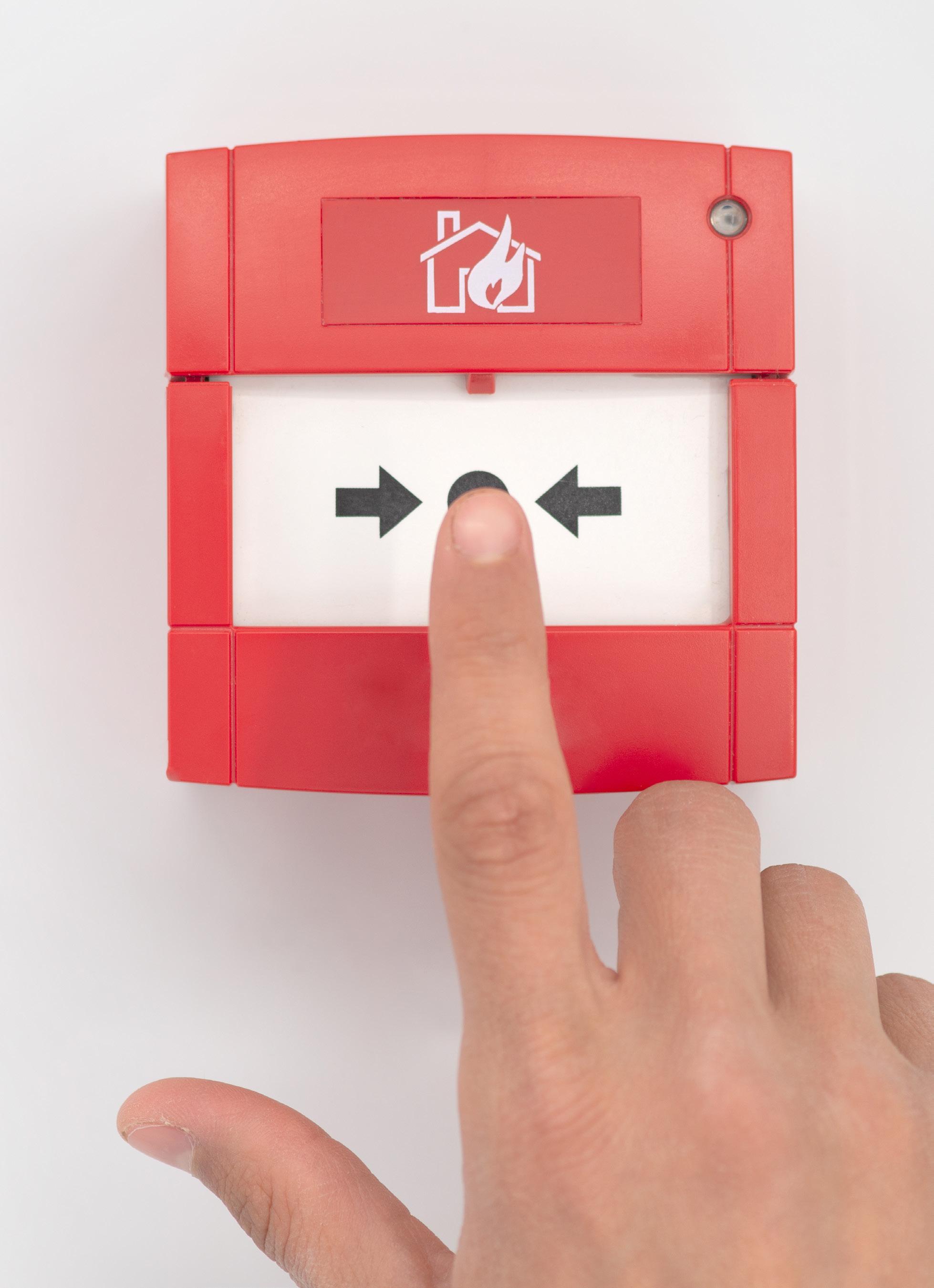
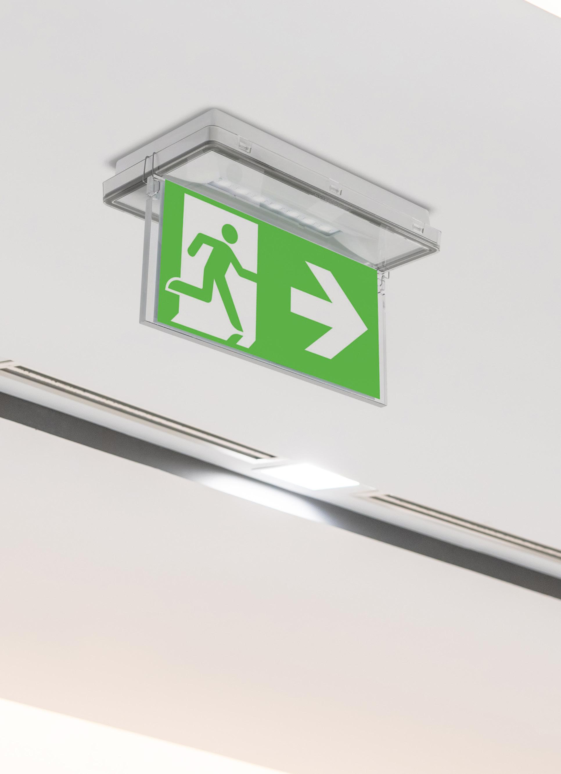
Emergency light remote testing at the touch of a button.
At Channel, we’re constantly working to give our customers the edge. With our unique system, any number of our compatible emergency lights can be individually tested with just one universal remote tester, saving time and money.
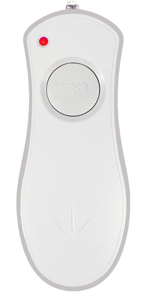
SIMPLE AS... 2 3 1 Point the Remote Tester at the compatible emergency fitting.
1 click for the monthly 5-second test.
2 clicks for the Annual 3 hour test. (One further click aborts test if necessary)
Any issues will be indicated by a flashing red LED until the fault is rectified and the light retested.
No need to switch off local lighting circuit during monthly 5-second and annual 3-hour tests
No hanging around for test to finish
Any faults indicated by flashing red LED
Fitting tested from up to 7m
Saves time and money
No need for a key switch
LOOK FOR THE SYMBOL
Overview

This popular fitting is now available with a self-test option and now benefits from a LiFePo4 long life lithium battery.
Weighing in at only 360g and measuring 260x100x61mm the Meteor LED fitting has a lumen output of 105lm in emergency mode from a 10 LED array, a hinged gear tray allows for easy installation.
The unit boasts an aesthetically pleasing design and is virtually maintenance free. The biggest success, as with the majority of our LED products, is that it operates on 20% of the power that a standard 8W fluorescent would consume.
Convert your Meteor Bulkhead fitting into an attractive emergency exit sign with a blade and diffuser kit.
Features
• Dimensions: 100mm (W) 260mm (L) 61mm (D)
• Cut out dimensions: 230mm (L) 85mm (W)
• Light source: LED
• Power consumption: 3W
• Uses typically 80% less power than that of an 8W fluorescent
• Maintained or non-maintained 3 hour emergency backup
• Weight: 0.36Kg
• Compliance: BS EN 60598-2-22 and other relevant standards
• Other accessories: Semi-recessing kit and diffuser with legend
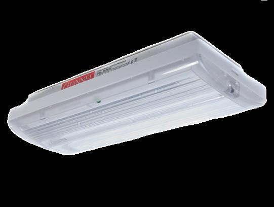
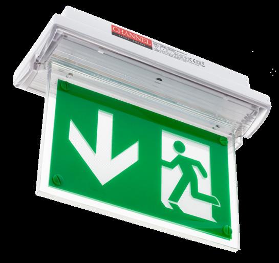
Photometric Spacing Data
Meteor
E/ME/M3/LED/IP65/LI Meteor low profile LED bulkhead complete with 10 LED array, IP65 version
E/ME/M3/LED/IP65/ST/LI Meteor IP65 low profile LED Bulkhead complete with 10 LED array, self test version
Accessories
E/ME/LED/SRK/1 Meteor LED semi-recessing kit
E/PIC/ME/LED/PACK Meteor LED sticker pictogram pack – (AD, AL, AR & AU) – Viewing distance 20m
E/PIC/ME/LED/BLADE Meteor LED Blade and Diffuser kit (Achieving IP65 rating) Light fitting not included – Viewing distance 20m
Replacement Parts
B/BATT/METEOR/LED Meteor LED battery – 3 cell stick AA NiCd 0.Ah – For use with NiCd Version
B/BATT/LI/Type1 LiFePo4 3.2v 1000mAh
Overview

The Meteor Maxi benefits from higher lumen output and a larger housing, making it a true 8W replacement.
Now with optional remote control and now benefits from a LiFePo4 long life lithium battery.
Measuring 110mm (W) 352mm (L) 64mm (D) the Meteor Maxi LED fitting has a lumen output of 140lm in emergency mode from a 10 LED array, a hinged gear tray allows for easy installation.
The unit boasts an aesthetically pleasing design and is virtually maintenance free. The biggest success, as with the majority of our LED products, is that it operates on 20% of the power that a standard 8W fluorescent would consume.
Features
• Dimensions: 110mm (W) 352mm (L) 64mm (D)
• Dimensions: Blade 160mm (H) + fitting
• Light source: LED
• Power consumption: 5W
• Uses typically 80% less power than that of an 8W fluorescent
• Maintained or non-maintained 3 hour emergency backup
• Compliance: BS EN 60598-2-22 and other relevant standards
• Other accessories: Semi-recessing kit and diffuser with legend
• Now with optional remote control
• Complete with exit legend kit
• Incorporates remote control testing facility
• Allows testing without disruption
• Universal remote control with approx range of 10m
• 31m viewing distance
Photometric Spacing Data (1 Lux)
E/MM/M3/LED/LI Meteor Maxi LED 3 Hour Maintained Emergency Light
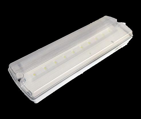
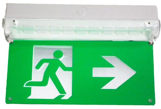
Maxi Pictogram Pack – (AD, AL, AR & AU)
– LiFePo4 3.2v 1500mAh
Features
• Now with increased light output, LiFeP04 long life lithium battery
• Dimensions: 115mm (W) 350mm (L) 75mm (D)
• Cut out dimensions for bezel: 100mm – 337mm
• Light source: LED (20 in unit)
• Power consumption: 7.3W
• Uses typically 80% less power than that of an 8W fluorescent
• Lumen output: 372lm (244lm emergency mode)
• Material: Polycarbonate diffuser and body
• IP65
• Maintained or non-maintained 3 hour emergency backup
• Weight: 0.95Kg
• Compliance: BS EN 60598-2-22 and other relevant standards
• Other accessories: Semi-recessing bezel available
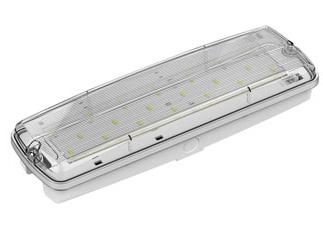
E/BK/M3/LED/3/LI Brook self contained, 3 hour maintained emergency LED light (Comes with remote control option)
E/BK/M3/LED/3/ST/LI Brook self contained, self-test 3 hour maintained emergency LED light
E/BEZ/BK/1 Brook semi-recessing bezel
E/PIC/ME/LED/PACK Brook pictogram pack – AD/AL/AR/AU
E/EM/RC Optional Remote Control
Replacement Parts
B/BATT/BROOK/2 Brook battery – 3 cell NiCd – For use with NiCd Version
B/BATT/LI/TYPE2 LiFePo4 3.2v 3000mAh
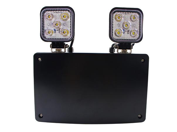
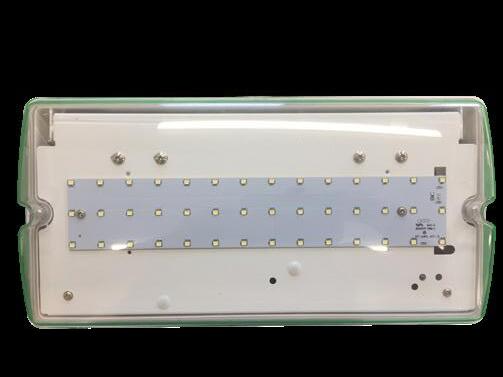
Overview
IP65 weatherproof rated and suitable for both internal & external environments. The SOLENT LED Bulkhead is designed to provide high light output in the event of a lighting power failure.
Features
• Long life LED technology
• Long life lithium battery
• Maintained/Non-maintained operation
• Can be ceiling or wall mounted
• Comes with Pictogram Pack
• Sleek and minimalistic design
• Polycarbonate construction
• Lightweight and easy to install
• Semi-recessing kit available
• Low environmental impact & running costs
• Meets BS EN 60598-1:2008 and other relevant standards
• IP65 weatherproof
• 154lm emergency output
• Hinged screwless gear tray
• 16mm or 20mm conduit entry
Photometric Spacing Data
Brook 3
Light Source White LED
IP Rating IP65
Emergency Duration 3 hours (minimum)
Lumen Output 154lm Maintained & Emergency output (6000K)
Mains Current (max.) 50mA (max) 35mA quiescent (3W)
Recharge Period Less than 24 Hours
Charge Indicator Integral green LED Red LED fault indicator
Changeover Voltage As per requirements of BS EN 60598-1:2008
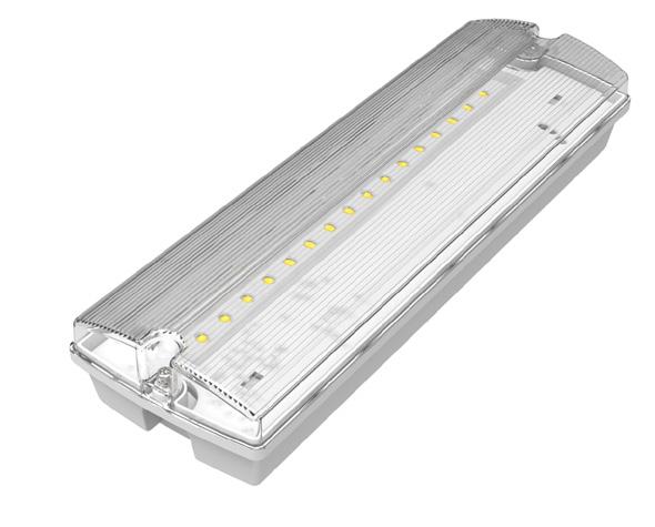
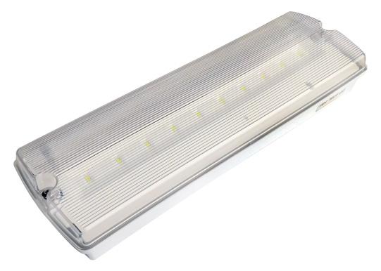
E/SOLENT/M3/LI Solent LED 3 Hour maintained emergency light with Pictogram Pack
E/BEZ/SOL Solent Semi Flushing Bezel
B/BATT/SOL Solent Battery – 3.6v 1.5Ah Ni-Cd - For use with NiCd Version
B/BATT/SOL/LI Lithium 3.2v 1500mAh Solent
Overview
The Stratos range of slave fittings for central battery & static inverter units is available in 24V, 50V, 110V & 230V AC/DC versions. The Stratos range offers a slimline profile in a contemporary design. Each light benefits from an IP65 housing and comes with a legend pack as standard.
Features
• Light source: LED
• Dimensions: 145mm (W) 265mm (L) 40mm (D), Blade 145mm (H)
• Power consumption: 1-2W
• Uses typically 80% less power than that of an 8W fluorescent
• Lumen output: 193-235lm
• IP65
• Maintained or non-maintained 3 hour emergency backup
• Compliance: BS EN 60598-2-22 and other relevant standards
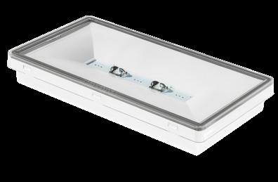
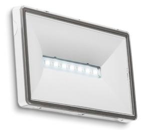
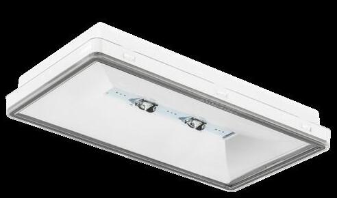
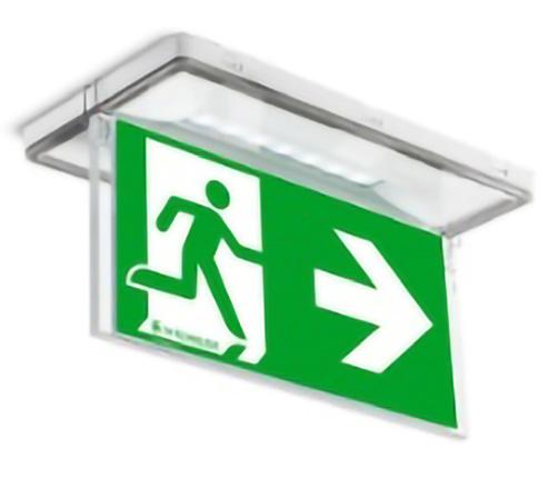
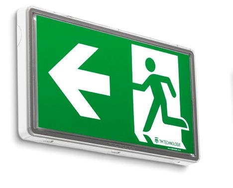
E/STRATOS/24
E/STRATOS/50
E/STRATOS/110
E/STRATOS/230
E/STRATOS/M3
E/STRATOS/M3/2W
Stratos 7x LED – 1W, IP65, 24V AC/DC slave bulkhead C/W exit sign pictogram (1W 198lm IP65)
Stratos 7x LED – 1W, IP65, 50V AC/DC slave bulkhead C/W exit sign pictogram (1W 198lm IP65)
Stratos 7x LED – 1W, IP65, 110V AC/DC slave bulkhead C/W exit sign pictogram (1W 198lm IP65)
Stratos 7x LED – 1W, IP65, 230V AC/DC slave bulkhead C/W exit sign pictogram (1W 198lm IP65)
Stratos 7x LED – 1W, IP65, 3 hr maintained bulkhead C/W exit sign pictogram (1W 198lm maintained/129lm Emergency IP65)
Stratos 7x LED – 2W, IP65, 3 hr maintained bulkhead C/W exit sign pictogram (2W 235lm maintained/238lm Emergency IP65)
E/STRATOS/HI Stratos High output 2xLED – 5W 210/250V AC 50/60hz (522lm)
E/STRATOS/COLD Stratos for temp range -20 °C to +40 °C – 214 LED, 2W, 210/25V AC, 50/60hz; 186/254 V DC
E/STRATOS/REC/KIT Stratos Semi Recessing Kit
E/STRATOS/PIC/KIT Stratos Hanging Blade legend C/W exit sign pictogram
Overview
Ultra High output (1500lm) Emergency light Ideal for high risk task lighting or high level mounting applications, the STRATOS-ULTRA offers a stylish solution to meet the higher lighting level required in BS 5266:2016. The Stratos Ultra gives amazing spacing even at very high mounting heights.
Features
• Approximately 15x the light output of a typical LED bulkhead
• Long life LED technology
• Maintained or non-maintained operation
• Polycarbonate construction with clear diffuser
• Hinged gear tray for easy installation
• Cable entry: rear, end & side of fitting
• Easy to install
• Low environmental impact
• Low running costs
• Low maintenance
• Meets BS EN 60598-2-22 and other relevant standards
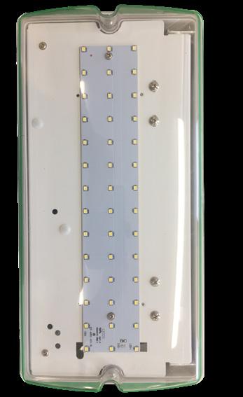
Photometric Spacing Data
Brook 3
Light Source 42x SMD 2835 White LED
IP Rating IP65
Emergency Duration 3 hours (minimum)
Lumen Output 1500lm Maintained & Emergency output (6000K)
Mains Current (Max.) 100mA (max.) 78mA quiescent (18W)
Recharge Period Less than 24 Hours
Charge Indicator
Integral green LED
Changeover Voltage As per requirements of BS EN 60598-1:2008
9.6V 4.5Ah Ni-Cd
Stratos Ultra
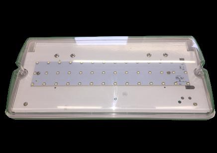
Overview
The athletic younger brother of our Alpine fitting, this is a streamlined LED Emergency exit sign which like the original is IP20 rated and compatible with our unique Remote Control Testing system and this iteration is supplied complete with a full legend set and now benefits from a LiFePo4 long life lithium battery.
Features
• Dimensions: 185mm (H) 317mm (W) 29mm (D)
• IP20
• Maintained or Non-maintained 3 hour emergency back-up
• 5 downward pointing LEDs to illuminate exit door.
• Low environmental impact
• Minimal maintenance
• Meets BS EN 60598-2-22 and other relevant standards
• Lightweight & easy to install
• Minimal maintenance
• Light Source – SMT LED 4W
E/AL/M3/SL/RC/LI Alpine Slim LED exit sign C/W full legend set
E/EM/RC Optional Remote Control
B/BATT/TYPE4 LiFePo4 3.2v 1500mAh
Features
• Dimensions: 210mm (H) 405mm (W) 55mm (D)
• Light source: LED
• Power consumption: 1.9W
• Uses typically 80% less power than that of an 8W fluorescent
• 1.9 LED equivalent to 8W fluorescent
• Material: White polycarbonate
• IP20
• Maintained or non-maintained 3 hour emergency backup
• Viewing distance: 32m
• Compliance: BS EN 60598-2-22 and other relevant standards
• Incorporates remote control testing facility
• Allows testing without disruption
• Unit tests for seconds or 3 hours
• Universal remote control with approx range of 10m
E/AL/M3/LED/LI Alpine LED exit sign (Comes complete with Arrow Up legend)
E/EM/RC Optional Remote Control
Additional Legends
E/PIC/AL/AD Alpine pictogram – arrow down
E/PIC/AL/AL Alpine pictogram – arrow left
E/PIC/AL/AR Alpine pictogram – arrow right
E/PIC/AL/AU Alpine pictogram – arrow up
Replacement Parts
B/BATT/ALPINE Alpine battery – 3 cell NiCd - For use with NiCd Version
B/BATT/TYPE1 LiFePo4 3.2v 1000mAh

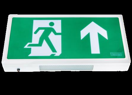
Overview
The Alpine Large offers the option of self test emergency exit signs for larger areas. With viewing distances up to 60m the Alpine large is suitable for almost any application where longer viewing distances are required.
Features
• Brushed Stainless Steel Housing
• Dimensions: 334mm (H) 622mm (W) 39mm (D)
• IP20
• Long life LED technology
• Maintained operation
• Metal body – Polycarbonate legend plate
• Self test technology
• Cable entry: rear, end & side of back box
• Low environmental impact
• Low running costs
• Low maintenance
• Meets BS EN 60598-2-22 and other relevant standards
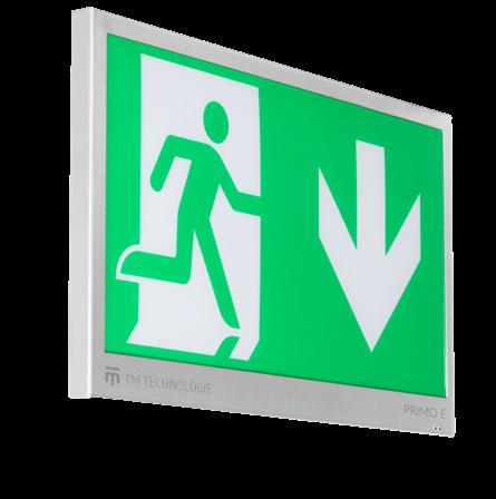
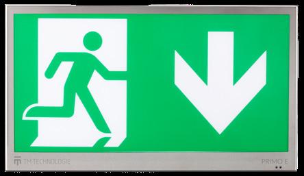
Light Source SMT LED
IP Rating IP20
Emergency Duration 3 hours (minimum)
Lumen Output 368lm
Mains Current (Max.) 150mA (max.) 40mA quiescent (3W)
Recharge Period Less than 24 hours
Charge Indicator Integral green charge & Red fault LED
Changeover Voltage As per requirements of BS EN 60598-1:2008
Battery 3.6V 3000mAh Nickel Cadmium
E/ALPINE/LARGE/60M Alpine Large maintained self-test exit sign 60m viewing distance
E/AL/LEG/LARGE/AU Alpine Large – legend – Arrow UP
E/AL/LEG/LARGE/AD Alpine Large – legend – Arrow DOWN
E/AL/LEG/LARGE/AL Alpine Large – legend – Arrow LEFT
E/AL/LEG/LARGE/AR Alpine Large – legend – Arrow RIGHT
Overview
The Exitor utilises LED technology for low cost, high output, emergency illumination.
Features
• Maintained or Non-maintained 3 hour emergency back-up
• LiFePo4 long life lithium battery
• Down light panel LEDs to illuminate exit door
• Low environmental impact
• Minimal maintenance
• Meets BS EN 60598-2-22 and other relevant standards
• Lightweight & easy to install, hinged cover
• Supplied with full legend set
Light Source SMT LED 3W
Colour Temperature 5500K
IP Rating IP20
Emergency Duration 3 hours (minimum)
Mains Voltage 230V 50Hz ± 10%
Mains Current CHARGING 55-90MA – 35mA quiescent (3W)
Recharge Period Less than 24 hour
Charge Indicator Integral green LED
Changeover Voltage As per the requirements of BS EN 60598-2-22
Temperature Range 5°C to 40°C
Weight 690gm
Battery 3.2v 1500mAh LiFePo4
Material & Finish Polycarbonate construction, white/opal finish
Exitor
E/EX/M3/LI EXITOR LED exit sign C/W full legend set
B/BATT/EX/LI LiFePo4 3.2v 1500mAh
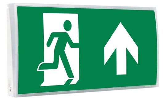
Overview
The ultra slim-line Razor LED emergency exit sign range offering hanging, recessed, flush mounted and wall/ceiling mounted versions. This compact range of LED exit signs comes complete with universal legend pack (other arrow options available).
Features
• Light source: LED 2W
• LiFePo4 long life lithium battery
• Uses typically 80% less power than that of an 8W fluorescent
• Material: Polycarbonate/Aluminium
• IP20
• Maintained 3 hour emergency backup
• Weight: 0.8Kg
• Compliance: BS EN 60598-2-22 and other relevant standards
• Viewing Distance 28 metres
• Comes complete with universal legend pack
• Comes with blank legend for single siding

E/RZ/M3/LED/W – Wall/Ceiling
E/RZ/M3/LED/H/LI
E/RZ/M3/LED/R/LI
E/RZ/M3/LED/F/LI
E/RZ/M3/LED/W/LI
Replacement Parts
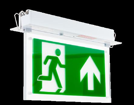
E/RZ/M3/LED/F – Recessed
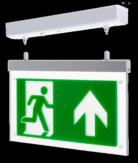
E/RZ/M3/LED/H – Hanging
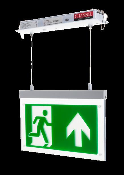
E/RZ/M3/LED/R – Hanging Recessed
Razor 3 hour maintained LED exit sign hanging – Maintained only Comes complete with universal legend pack (arrows left/right, up/down, blank)
Razor 3 hour maintained LED exit sign hanging recessed – Maintained only Comes complete with universal legend pack (arrows left/right, up/down, blank)
Razor 3 hour maintained LED exit sign flush recessed – Maintained only Comes complete with universal legend pack (arrows left/right, up/down, blank)
Razor 3 hour maintained LED exit sign wall/ceiling fitting – Maintained Comes complete with universal legend pack (arrows left/right, up/down, blank)
E/PIC/RZ/PACK Razor Pictogram Set
B/BATT/RZ/LI LiFePo4 3.2v 1500mAh - For use in Wall, Recessed & Flush
B/BATT/RZ/H/LI LiFePo4 3.2v 1500mAh - For use in Hanging Version (C/W Mounting Plate)
Overview
The 5-in-1 emergency exit sign means you will always have the correct mounting method. The 5-in-1 is supplied with a full legend set and is further enhanced by our unique remote control testing option. It can be installed in both switchable maintained or nonmaintained option.
Features
• Maintained or Non-maintained 3 hour emergency back-up
• LiFePo4 long life lithium battery
• Incorporates 3.6V 1.5Ah NiCd battery
• 30m viewing distance
• Low environmental impact
• Minimal maintenance
• Meets BS EN 60598-2-22 and other relevant standards
• Full legend set included
• IP20
5 Mounting options supplied as standard:
• Wall
• Ceiling
• Flag
• Recessed
• Suspended
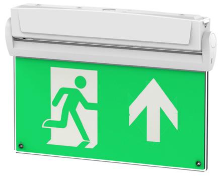
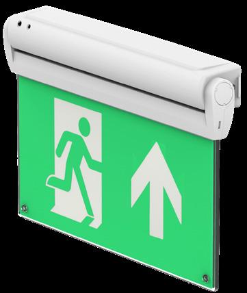

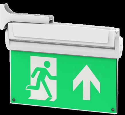
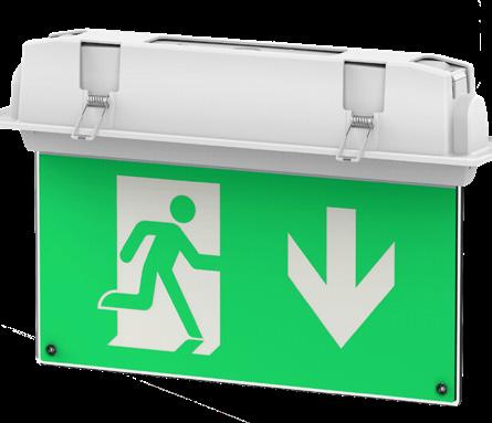
E/5in1/LI 5-in-1 LED exit sign C/W full legend set and five mounting option brackets
E/5IN1/ST/LI 5-in-1 LED exit sign - Self Test C/W full legend set and five mounting option brackets
E/EM/RC Remote Control Test Unit (Optional)
B/BATT/TYPE4
Overview
Our Forest self-test range offers an LED exit sign in white, brass, chrome & satin chrome finishes.Our Forest self-test range offers an LED exit sign in white, brass, chrome & satin chrome finishes. The Forest comes with 1M chains which can be shortened or extended to suit the installation requirements.
Other mounting options are available using the wall or flag mounting brackets.
Features
• Light source: LED 2W
• LiFePo4 long life lithium battery
• Uses typically 80% less power than that of an 8W fluorescent
• Material: Polycarbonate/Aluminium
• IP20
• Maintained 3 hour emergency backup
• Weight: 0.8Kg
• Compliance: BS EN 60598-2-22 and other relevant standards
• Viewing Distance 32m
• Comes complete with universal legend pack
• Comes with legend blank for single siding
• Self test as standard
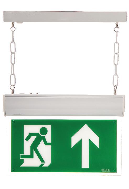
E/CHFO/M3/L/WHST Forest LED 3 hour maintained in white (Self-test complete with arrow up legend)
E/CHFO/M3/L/BRST Forest LED 3 hour maintained in brass (Self-test complete with arrow up legend)
E/CHFO/M3/L/CHST Forest LED 3 hour maintained in chrome (Self-test complete with arrow up legend)
E/CHFO/M3/L/SAST Forest LED 3 hour maintained in satin (Self-test complete with arrow up legend)
Additional Legends
S/LEG/FO/AU Double sided arrow up legend for Forest (insert only)
S/LEG/FO/ALR Double sided arrow left/right for Forest (insert only)
S/LEG/FO/AD Double sided arrow down legend for Forest (insert only)
Mounting Brackets
E/CHFO/WMB/SI Forest Satin Silver Wall Mounting Bracket
E/CHFO/WMB/WH Forest White Wall Mounting Bracket
E/CHFO/WMB/BR Forest Brass Wall Mounting Bracket
Flag Mounting Brackets
E/CHFO/FMB/WH Forest white flag mounting bracket
E/CHFO/FMB/SI Forest satin silver flag mounting bracket
E/CHFO/FMB/BR Forest brass flag mounting bracket
Replacement Parts
Please contact Channel
Features
• Dimensions: 230mm (H) 355mm (W) 115mm
• Cut out dimensions: (L) 335mm (W) 95mm (D) 60mm
• Light source: LED
• Power consumption: 2.1W
• LiFePo4 long life lithium battery
• Uses typically 80% less power than that of an 8W fluorescent
• Material: White, brass and chrome
• IP20
• Self test as standard
• Can be switched internally to maintained or non-maintained operation
• Viewing distance: 25m
• Weight: 1.5Kg
• Compliance: BS EN 60598-2-22 and other relevant standards
• Other accessories: Double sided pictograms available
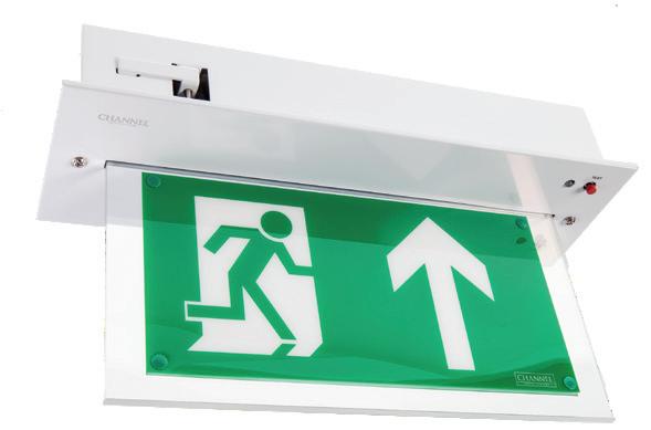
E/CHVL/M3/L/WHST Vale LED 3 hour maintained white (Self-test complete with legend arrow up)
E/CHVL/M3/L/BRST Vale LED 3 hour maintained brass (Self-test complete with legend arrow up)
E/CHVL/M3/L/CHST Vale LED 3 hour maintained chrome (Self-test complete with legend arrow up)
Additional Legends
S/LEG/VL/AD Vale double sided pictograms arrow down legend (insert only)
S/LEG/VL/ALR Vale double sided arrow pictograms left/right (insert only)
S/LEG/VL/AU Vale legend arrow up insert pictograms only (insert only)
Features
• Dimensions: 175mm (H) 335mm (W) 38mm (D)
• Light source: LED
• Power consumption: 2.1W
• LiFePo4 long life lithium battery
• Uses typically 80% less power than that of an 8W fluorescent
• Material: White mild steel
• IP20
• Self test as standard
• Can be switched internally to maintained or non-maintained operation
• Viewing distance: 32m
• Weight: 1.0Kg
• Compliance: BS EN 60598-2-22 and other relevant standards
• Other accessories: Pictograms available

E/DA/M3/LED/3/ST Dale LED 3 hour maintained self-test complete with arrow up legend
Additional Legends
S/LEG/DA/AL/3 Pictogram arrow left
S/LEG/DA/AR/3 Pictogram arrow right
S/LEG/DA/AD/3 Pictogram arrow down
S/LEG/DA/AU/3 Pictogram arrow up
Overview No power needed! With its self-luminous tritium power, easy installation and sleek design, the Betalux exit sign is revolutionizing the emergency exit industry.
The Betalux is vandal resistant, waterproof, explosion proof and incapable of generating sparks, making it ideal in harsh and dangerous environments such as offshore oil rigs, mines, refineries, munitions plants and chemical factories.
Having no wires it is an ideal choice where architectural integrity is a priority, such as heritage sites, hotels, office buildings, theatres and restaurants.
Features
• Dimensions: 218mm (H) 396mm (W) 28mm (D)
• Last up to 20 years based on initial brightness option
• Aluminum frame in polycarbonate window
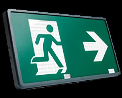
Illumination Source: Betalux tubes manufactured from borosilicate (hard) glass internally coated with zinc sulfide phosphor and filled with tritium gas. No electrical energy source required.
Brightness: Minimum initial brightness at time of manufacture of 0.15 foot lambert. Brightness variation between letters does not exceed ratio of 3 to 2.
Construction: Cased in high impact ABS fire-retardant plastic. Legend covers: red, green, or black. Frame colors: Aluminum, white or black.
Betalux
SP/BX/AU/DG/EN Self Powered Exit Sign C/W Arrow Up Legend
SP/BX/AD/DG/EN Self Powered Exit Sign C/W Arrow Down Legend
SP/BX/AL/DG/EN Self Powered Exit Sign C/W Arrow Left Legend
SP/BX/AR/DG/EN Self Powered Exit Sign C/W Arrow Right Legend
Overview
We are excited to bring you vastly improved lumen outputs with our new generation Grove twinspot fittings! Both fittings now boast an impressive 720lm output!
The Grove range has new & improved head design and is also available as an IP65 Self Test Version.
Features
• Dimensions:250mm (H) 300mm (W) 70mm (D),
• No of LEDs per head: 30 – Low maintenance
• Power consumption: 15W (emergency mode)
• Uses 50% power than that of a Tungsten halogen
• Lumen output: 720lm (emergency mode)
• Material: White metal body/polycarbonate lamps & lenses
• IP20 – Non-maintained mode only
• Weight: 2.20Kg
• Compliance: BS EN 60598-2-22 and other relevant standards
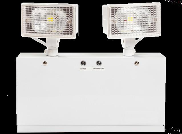
Photometric Spacing Data
Features
• Dimensions: 279mm (H) 292mm (W) 68mm (D)
• No of LEDs per head: 30 – Low maintenance
• Power consumption: 3W (emergency mode)
• Uses 50% power than that of a Tungsten halogen
• Lumen output: 368lm (emergency mode)
• Material: White polycarbonate body, lamps & lenses
• IP65
• Weight: 1.08Kg
• Compliance: BS EN 60598-2-22 and other relevant standards
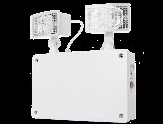
Photometric Spacing Data E/GR/NM3/LED/LI
Parts
E/GR/NM3/IP65/RC/LI
E/GR/NM3/LED/IP65/ST/LI
Parts
Twin
floodlight 3 hour non-maintained with white lamps. Remote control test version.
Twin 2x LED floodlight 3 hour non-maintained with white lamps. Self-test version.
Overview
Ultra High Output Emergency Twinspot. The Grove Ultra LED twinspot is ideal for use in areas with high ceilings or areas requiring high emergency lux levels – The Grove Ultra gives 1800 lumen output in the emergency mode! It also offers a maintained operation!
Features
• Approximately 3x the light output of a typical LED twinspot
• Long life LED technology
• Maintained or non-maintained operation
• Polycarbonate body with metal lamps
• May be mounted in any orientation
• Cable entry: rear, end & side of fitting
• Easy to install
• Low environmental impact
• Low running costs
• Low maintenance
• Meets BS EN 60598-2-22 and other relevant standards
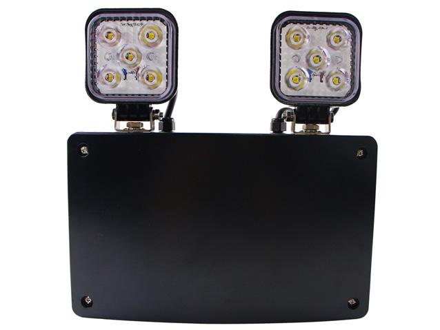
Photometric Spacing Data
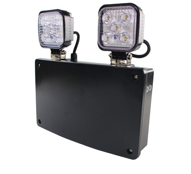
Light Source 2(5x3W) Osram
IP Rating IP65
Emergency Duration 3 hours (minimum)
Mains Voltage 230V 50Hz ± 10%
Mains Current (Max.) 90mA (18W)
Recharge Period Less than 24 hours
Charge Indicator Integral green LED
Changeover Voltage As per the requirements of BS EN 60598-2-22
Parts
Overview
Our new GU32 IP65 twinflood offers a high performance, cost-effective emergency lighting in warehouses, factories, atriums, exterior escape routes & large open areas.
The GU32 IP65 gives 368lm in the emergency mode.
High specification optic design and performance allows increased spacing providing reduced cost.
Supplied with hanging kit for downward pointing installation & integral driver and LiFePo4 battery pack.
Features
• Self test
• Versatile multi-functional use, interior & exterior
• LiFePo4 long life lithium battery
• May be mounted in any orientation
• Tough polycarbonate housing
• Carrying handle for portability
• Non-maintained
• Minimal maintenance
• Easy installation
• IP65 ingress protection
• RoHS compliant
• Excellent luminaire spacings
• 3 Watt power consumption
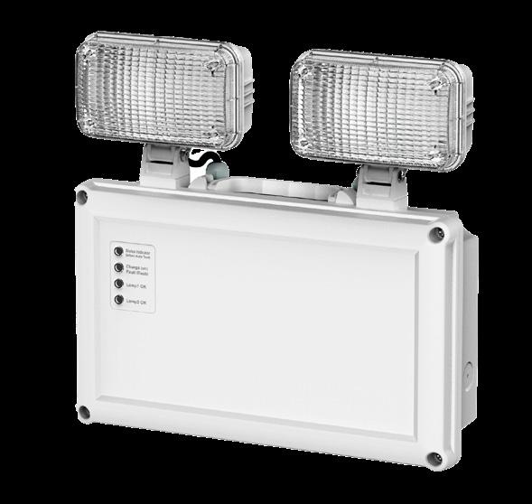
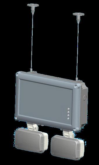
Spacing Data
E/GU32/IP65/ST/LI IP65 3 Hour Non-Maintained emergency twinflood with self test
Replacement Parts
Overview
The GU32 LED twinspot offers a Non-Maintained IP20 LED Twin Spot for interior installations provides up to three hours of emergency lighting thanks to the 1 x 3.6V, 4.5Ah battery. The polycarbonate body, in a white finish provides the ideal choice for warehouses, factories, open areas & corridors.
Features
• IP20
• Long life LED technology
• LiFePo4 long life lithium battery
• Non-maintained operation
• Polycarbonate construction
• May be mounted in any orientation
• Cable entry: rear, end & side of fitting
• Easy to install
• Low environmental impact
• Low running costs
• Low maintenance
• Meets BS EN 60598-2-22 and other relevant standards
Photometric Spacing Data
GU32
Transverse to Wall Transverse to Transverse
Light Source SMT LED 2 x 30pcs
IP Rating IP20
Emergency Duration 3 hours (minimum)
Lumen Output 368lm
Mains Current (max) 150mA (max) 40mA quiescent (3W)
Recharge Period Less than 24 hours
Charge Indicator Integral green charge & lamp healthy LEDs
Changeover Voltage As per requirements of BS EN 60598-1:2008
Battery 3.2V 5500mAh LiFePO4
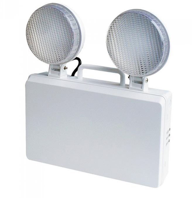
E/GU32/LI 3 Hour Non-Maintained emergency twinflood
Replacement Parts
B/BATT/GU32/LI LiFePO4 3.2V 5500mAh
Overview
Azelio Surface is a compact, high specification surface mounted emergency LED downlight supplied with both open area and escape route lenses, our new Azelio Surface emergency downlight offers a high performance, cost-effective emergency lighting downlight for indoor use where aesthetics are of prime importance.
The Azelio Surface comes with two lens options, open area (150lm) & corridor (137lm), it is further enhanced by the addition of a remotecontrol testing option, which ensures simple & cost-effective testing.
High specification optic design and performance allows increased spacing providing reduced cost, with up to 15m spacing between fittings (3m mounting height).
Supplied with integral driver and LiFePo4 Lithium Battery.
Features
• Versatile multi-functional use (escape and open area anti-panic)
• LiFePo4 long life lithium battery
• Supplied with both open area & corridor lenses
• Remote Control test facility (Additional control unit required)
• Tough polycarbonate housing
• Suitable for surface mounting
• Two types of high performance
• lenses for escape route or open area illumination
• Non-maintained
• Minimal maintenance
• Easy installation
• IP20 ingress protection
• RoHS compliant
• Excellent luminaire spacings of up to 15m for corridor version
• BESA Box fixings
Photometric Spacing Data
Surface
Azelio Surface
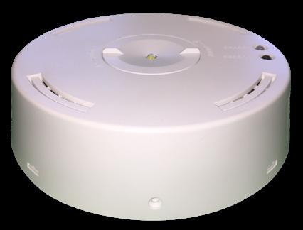
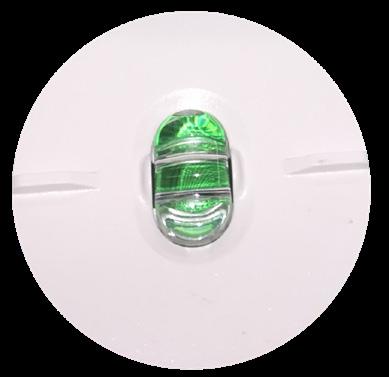
Overview
Azelio Recessed is a compact, Self test or remote control. 3W high specification recessed emergency LED downlight supplied with both open area and escape route lenses, our new Azelio recessed emergency downlight offers a high performance, cost-effective emergency lighting downlight for indoor use where aesthetics are of prime importance.
The Azelio Recessed comes with two lens options, open area (158lm) & corridor (143lm).
High specification optic design and performance allows increased spacing providing reduced cost, with up to 15m spacing between fittings (3m mounting height).
Features
• Versatile multi-functional use (escape and open area anti-panic)
• LiFePo4 long life lithium battery
• Supplied with both open area & corridor lenses
• Auto self test
• Tough polycarbonate housing
• Suitable for recessed mounting
• Non-maintained
• Minimal maintenance
• Easy installation
• IP20 ingress protection
• RoHS compliant
• Excellent luminaire spacings of up to 15m for corridor version
• 70-75mm cutout
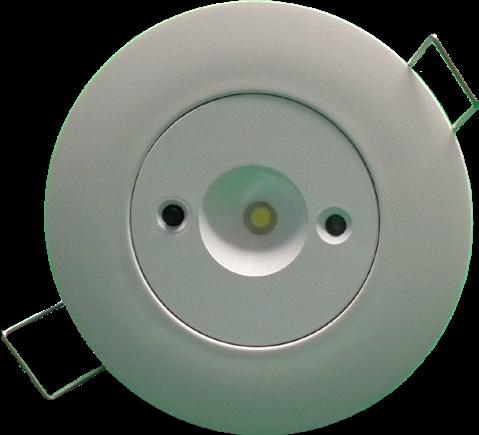
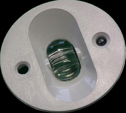
Overview
The Glade 1W Non-Maintained emergency Downlight offers a discrete emergency option. Now supplied with both open area and corridor lenses, the Glade 1w is further enhanced with a long life LiFePo4 lithium battery.
Features
• LiFePo4 Battery
• Open Area & Corridor Lens
• 6000K CCT
• Long life LED technology
• Non-maintained 3-hour emergency back-up
• Slimline driver module with sleek and minimalistic design
• Simple plug and go installation
• Low maintenance and low environmental impact
• 40mm cut out
Photometric Spacing Data
Glade 1W
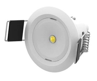
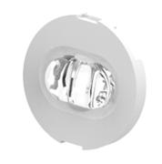
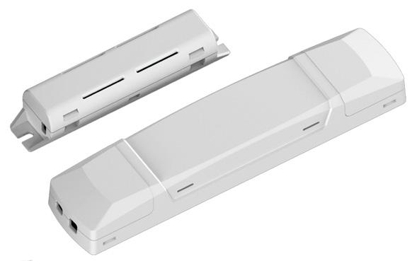
Overview
The Glade 5W Maintained emergency Downlight offers a discrete emergency option. Now supplied with both open area and corridor lenses, the Glade 5W is further enhanced with a long life LiFePo4 lithium battery and now benefits from our Smart Test remote control testing system.
Features
• LiFePo4 Battery
• Open Area & Corridor Lens
• 6000K CCT
• Long life LED technology
• Maintained 3-hour emergency back-up
• Slimline driver module with sleek and minimalistic design
• Simple plug and go installation
• Low maintenance and low environmental impact
• 60mm cut out
Photometric Spacing Data
Glade 1W
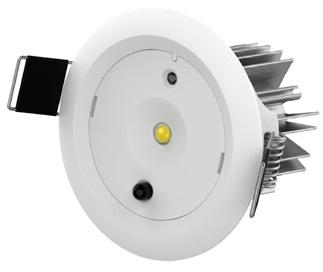
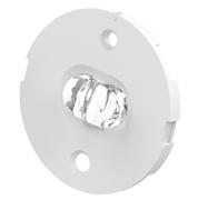
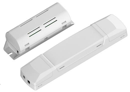
Open Area Transverse to Wall Transverse to Transverse Axial to Axial Axial to Wall
Mounting Height 1 Lux - 262lm 1
Glade 1W
Corridor 3m Wide Transverse to Wall Transverse to Transverse Axial to Axial Axial to Wall Mounting Height 1 Lux - 241lm 1 Lux - 241lm 1 Lux - 241lm 1 Lux - 241lm 2.5m 6.1m 13.3m
Light Source LED
IP Rating IP20
Dimensions Lamp: Ø 70mm, Module: 180 x 40 x 25mm, Battery Module: 117 x 40 x 35mm
Lumen Output Open Area 262Lm – Corridor 241Lm
Power Consumption 5W
Weight Module and battery 390gm
Material Polycarbonate Module
Compliance BS EN 60598-2-22 and all other relevant standards and regulations
Battery 3.2V 5.5Ah LiFePo4
Glade 5W
E/GL/LED/M3/5W/WH/LI 5W Maintained Emergency Downlight - LiFePo4 long life lithium battery
Overview
The Glen is a 3W recessed LED downlight; LED technology and provides excellent value for money. The Glen offers suBS tantial energy & maintenance savings over its lifetime & benefits from a LiFePO4 battery.
Features
• LiFePO4 battery
• Long life LED technology
• Polycarbonate/metal construction
• Simple ‘plug & go’ installation
• Non maintained operation 3 hours emergency backup
• Low environmental impact
• Colour temperature 5500K
• Green charge LED
• Meets BS EN 60598-2-22 and other relevant standards
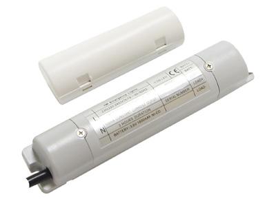
Photometric Spacing Data
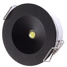
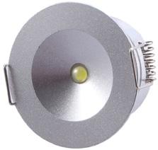
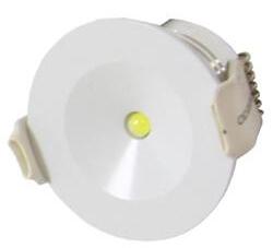
Overview
Offering open area and escape route lenses our Azelio emergency downlight offers a simple & cost effective emergency lighting solution for most applications.
The 95-100mm cut out makes it ideal to replace existing tungsten/dichroic downlights.
High specification optic design and performance allows increased spacing providing reduced cost, with up to 15m spacing between fittings (3m mounting height).
Supplied with integral driver and lithium battery pack pre-wired for easy installation.
Features
• Pre-wired for easy installation
• Ideal size to replace existing downlights
• High output LED light source = less fittings
• Integrated long life lithium battery
• Open area & corridor comes supplied as standard
• Built in ‘push to test’ switch
• Non-Maintained
• Input Voltage: 220-240V 50/60Hz
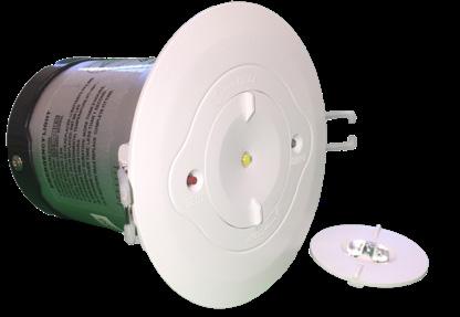
Photometric Spacing Data
• Light Source: SMD LED
• LED Wattage: 3W LED
• IP20
• 6000k-7000k
• Weight: Open Area: 280g Corridor: 282g
• Bezel dia. 110mm
• Lumen output: Open Area: 158lm Corridor: 176lm
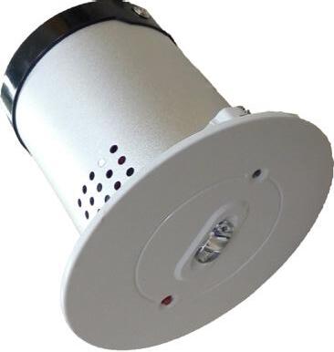
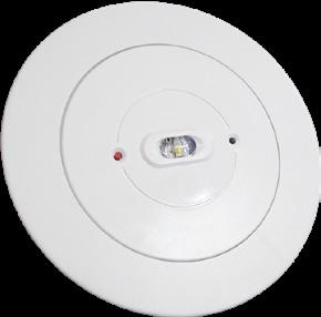
Overview
Azelio Track emergency LED available as an open area downlight or exit sign. High specification track mounted emergency LED downlight supplied with a full set of legends, our new Azelio Track mounted exit sign offers cost-effective emergency lighting where track lighting is installed.
It is supplied with a 3 circuit Global Track adapter. Available in black or white (green exit legend). Supplied with integral driver. Track adapter can be easily swapped to match almost any track profile.
Features
• Track mounted 3 hour Emergency LED
• Supplied with full legend set (exit sign only)
• Quick & simple to install
• Suitable for Global track mounting
• Maintained
• Minimal maintenance
• Easy installation
• IP20 ingress protection
• RoHS compliant
• White & black options
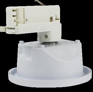
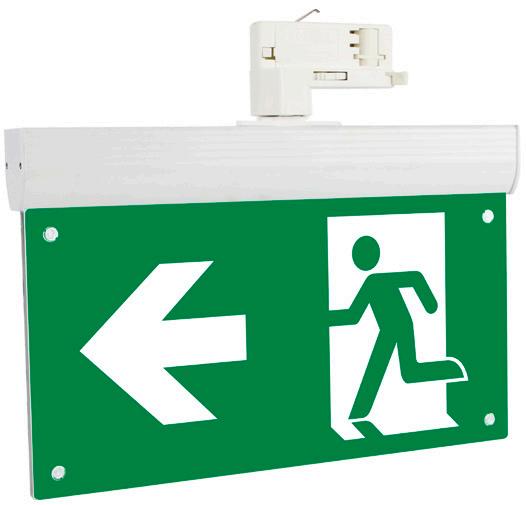
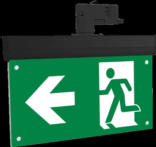
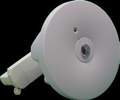
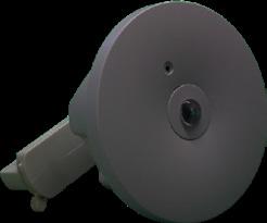
E/AZ/TRACK/EXIT/LI Azelio Track exit sign C/W 4 legends & blank legend
E/AZ/TRACK/EXIT/BK/LI Azelio Track exit sign C/W 4 legends & blank legend – BLACK
E/AZ/TRACK/COA/LI Azelio track downlight with corridor & open area lenses – White
E/AZ/TRACK/COA/BK/LI Azelio track downlight with corridor & open area lenses – Black
Overview
The Track emergency light is a Non-Maintained Emergency Light.
It is supplied with a 3 circuit Global Track adapter. It is designed to provide high light output in the event of an emergency.
Track adapter can be easily swapped to match almost any track profile.
Features
• Dimensions: 320mm (L) 67mm (W) 40mm (D), excludes track adapter
• Pre-wired for easy installation
• Long Life LED technology
• Quick & simple to install
• Line Voltage: 220-240Vax, 50~60Hz
• Lamp Type: 3W White LED
• 3 hr emergency lighting duration
• Non-maintained operation
• CE Approved
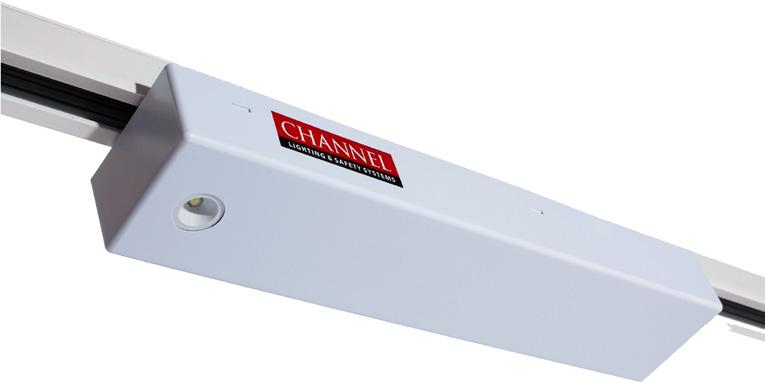

Overview
The i-monitor Emergency is a comprehensive DALI based emergency light testing system. i-Monitor Emergency has been designed to provide a flexible, powerful and user friendly emergency lighting testing and reporting system.
The i-Monitor control panels are standard Apple iPad devices utilising a specific ‘App’ which is intuitive and very easy to use for both the commissioning engineer as well as well as a user. The ‘Appx’ is used to configure all the connected DALI emergency devices.
Features
• App based Emergency Light testing system
• Simple emergency duration & function test scheduling
• System diagnostic information
• Control HuBS connect up to 128 DALI lights
• I-Pad can control 10 huBS (1280 DALI lights)
• Simple menu navigation
• Records results & sends notification emails
• Scalable to 10,240 DALI Lights
• Air print compatible
• Master i-Pad can control 10 huBS
• Each hub has 2 outputs
• Up to 8 x iPads can be networked giving a total of 10,240 DALI lights
• iPad can be moved to log on to any hub with a wireless access point, or additional iPads can be used
i-Monitor PRO DALI Lighting Control & Emergency Light Test
The i-Monitor Pro uses a PC or laptop for the control & monitoring of the system. It is simply linked to any Multi-Controller.
Featuring an intuitive graphic user interface and commissioning tool, coupled with a very powerful database engine, the system provides an intuitive and simple way to initially set-up the system, as well as presentation of live real time status. A wide range of sensors, switch input interfaces and scene button panel options ensure market leading functionality and flexibility.
The i-Monitor PRO offers a solution for Commercial applications such as offices, schools, universities, hotels, airports etc.
The simple display provides clear and concise visualisation of the lighting control scheme. Unlimited control groups, system Diagnostics, alert messages power consumption data, & emergency light test reports further enhance the benefits of the system.
The Monitor Pro software can be used to configure any connected DALI device to form local control groups. DALI devices do not need to be physically in the same DALI field network to function as part of a control group. Thus a control group can be as simple as a single switch controlling one local light, right up to say, a switch controlling the whole building. The i-Monitor PRO offers a sophisticated lighting control & emergency light monitoring system.
Any DALI type 8 light can be monitored & controlled.
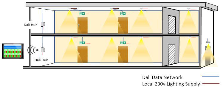
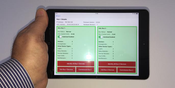
Multi Controller
Each Multi-Controller can control 10 huBS . Each hub has 2 outputs.
Each output can control 64 lights (128 per hub) 128 x 10 huBS = 1280 lights.
The i-Monitor Pro uses a simple graphical display designed to provide clear and simple visualisation and management of lighting control systems.
Icons representing system elements can be overlaid on building schematics and incorporated into a site plan. These icons are dynamic and allow the state of the system and current output levels to be viewed at a glance giving a real-time system wide view.
We are able to offer a wide range of iD-Mesh compatible emergency lights; the most popular are shown below.
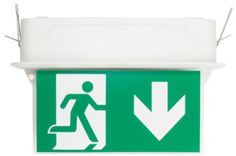
E/EXDA/1
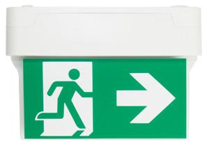
E/EXDA/2
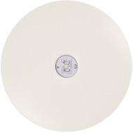
E/DLDA/1
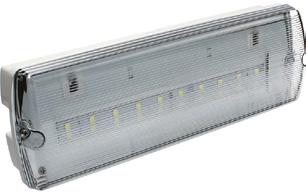
E/BHDA/1
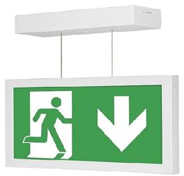
E/EXDA/3
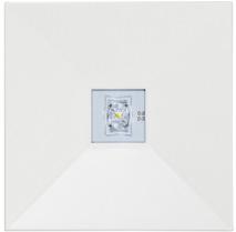
E/DLDA/2
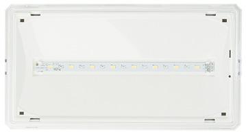
E/BHDA2
Exit Signs
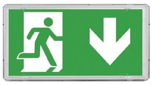
E/EXDA/4
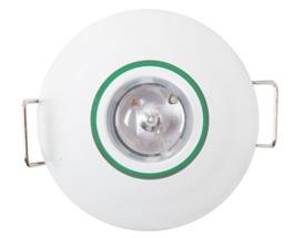
E/DLDA/3
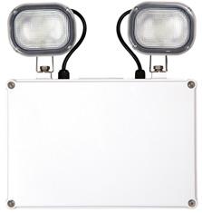
E/TSDA/1

E/SOHO/M3/DALI
E/EXDA/1** DALI Maintained/Non-Maintained Recessed mounted LED Exit sign - White ** add AU, AD, ALR
E/EXDA/2** DALI Maintained/Non-Maintained surface mounted LED Blade Exit sign - White ** add AU, AD, ALR
E/EXDA/3** DALI Maintained/Non-Maintained Suspended mounted LED Exit sign - White ** add AU, AD, ALR
E/EXDA/4 DALI emergency Maintained/Non-Maintained IP65 3W exit sign C/W full legend pack
Downlights
E/DLDA/1/** DALI Emergency 3W Circular LED surface mounted ** add open or corridor lens OA/CO
E/DLDA/2/** DALI Emergency 3W Square LED surface mounted ** add open or corridor lens OA/CO
E/DLDA/3/** DALI 3W LED emergency downlight - recessed ** add open or corridor lens OA/CO
Bulkheads
E/BHDA/1 DALI Emergency 2W LED DALI Emergency Bulkhead Non-Maintained 288 Lumens-Clear lens
E/BHDA/2 DALI 3W IP65 bulkhead
Twinspots
E/TSDA/1 DALI IP65 6W LED Twinspot Emergency providing 610 Lumen output
Ceiling Light
E/SOHO/M3/DALI DALI Soho 21W maintained ceiling light
Ordering Details: Please contact us with your requirements for us to provide a customised solution to meet your system requirements.
Overview
We are proud to introduce our new iD-Mesh wireless DALI emergency lighting testing system.
iD-Mesh offers a cost effective solution which overcomes the issue of installing a data network.
Each emergency light is incorporated in to a wireless data network and forms part of the transmit/receive mesh.
System monitoring & reports are all via the cloud and can be viewed on any internet connected device. This ensures that your emergency lighting is functioning & compliancy data is available.
Any issues are immediately reported advising the exact location & nature of the fault, ensuring a first time fix.
Features
• Each iD-Mesh hub can control up to 239 lights
• Multiple –iD-Mesh huBS can be used to create systems WITH NO LIMIT ON SIZE
• ID-Mesh huBS have a range of up to 500m line of sight and up to 100m within a building
• The iD-Mesh wireless nodes can be fitted in to any suitable DALI emergency light
• Each hub reports to the cloud platform which can be viewed at any location via a web browser
• The nodes have an approximate range of 50m
• The mesh technology enables all nodes to both receive & transmit data to the hub, this ensures that signals have multiple paths to/from the node
• Persistent gateways mean that if communication is lost, data is stored until communication is re-established.
• Transmits at Long Range 868Mhz
• Commissioning & system changes are carried out using an “iD-Mesh Works” robust tablet
• The iD-Mesh Works tablet builds the mesh at the push of a button

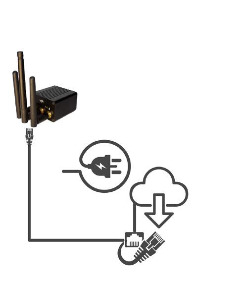


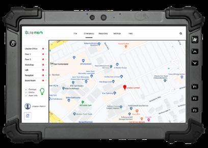
E/ID/MESH/WORKS
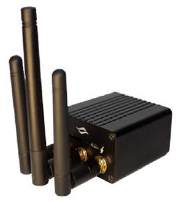
E/ID/MESH/HUB
We are able to offer a wide range of iD-Mesh compatible emergency lights; the most popular are shown below.
E/EXDA/1/ID
E/EXDA/2/ID
E/DLDA/1/ID
E/BHDA/1/ID
E/EXDA/3/ID
E/DLDA/2/ID
E/BHDA2/ID
iD-Mesh Wireless DALI Emergency Light Testing System
Exit Signs
E/EXDA/4/ID
E/DLDA/3/ID
E/TSDA/1/ID
E/SOHO/M3/DA/ID/ID
E/EXDA/1**/ID DALI Maintained/Non-Maintained Recessed mounted LED Exit sign-White ** add AU, AD, ALR
E/EXDA/2**/ID DALI Maintained/Non-Maintained surface mounted LED Blade Exit sign-White ** add AU, AD, ALR
E/EXDA/3**/ID DALI Maintained/Non-Maintained Suspended mounted LED Exit sign-White ** add AU, AD, ALR
E/EXDA/4/ID DALI emergency Maintained/Non-Maintained IP65 3W exit sign C/W full legend pack
Downlights
E/DLDA/1/**/ID DALI Emergency 3W Circular LED surface mounted ** add open or corridor lens OA/CO
E/DLDA/2/**/ID DALI Emergency 3W Square LED surface mounted ** add open or corridor lens OA/CO
E/DLDA/3/**/ID DALI 3W LED emergency downlight-Recessed ** add open or corridor lens OA/CO
Bulkheads
E/BHDA/1/ID DALI Emergency 2W LED DALI Emergency Bulkhead Non-Maintained 288 Lumens - Clear lens
E/BHDA/2/ID DALI 3W IP65 bulkhead
Twinspots
E/TSDA/1/ID DALI IP65 6W LED Twinspot Emergency providing 610 Lumen output
Ceiling Light
E/SOHO/M3/DA/ID DALI Soho 21W maintained ceiling light
Downlights
E/ID/MESH/HUB/ID WiFi Hub – Controls up to 239 lights
E/ID/MESH/WORKS/ID iD-Mesh system tablet used to commission & amend the system
E/ID/MESH/NODE/ID WiFi Node – fitted to suitable DALI light
What is DALI?
DALI stands for Digital Addressable Lighting Interface. In other words, it is a worldwide standardised digital lighting interface. The DALI standard, specified in IEC standard 60929, ensures interchange ability and compatibility of lighting products from different manufacturers.
The DALI system was created by leading lighting manufacturers who recognised the need for a common interface. DALI was engineered to meet the new challenges of lighting control – more flexibility, greater scalability of control and faster installation.
Basic Rules for DALI products & systems
There are a few basic rules to take into account when planning and wiring a DALI system.
Max. Addresses per system (subnet) – 63 It’s officially 64, but you need to leave one free, to make system updates easier.
Polarity – DALI connections are not polarity sensitive.
Max. DALI current per system (subnet) – 250mA DALI supply. The total current that is supplied by all sources of the control system must not be more than 250mA.
DALI wiring safety rating
DALI wiring and connections should be treated like Mains voltage wiring. Though the signal is 16 volts the hardware is not SELV rated (Safety Extra Low Voltage).
Which wire for DALI cable?
You must use 2-conductor, mains rated wire.
The DALI System at work
Traditional DALI allows for individual light fittings to be controlled and grouped together into logical areas. The DALI protocol allows for a maximum of 64 fittings on a single network and the network can be broken up into 16 different possible areas.
DALI enables total control
Compared to a fixed output installation, the dimming and individual control capability provided by DALI enables considerable energy savings. In combination with dimmable drivers, presence and daylight sensors, energy savings of up to 80 per cent can be achieved.
If the operation of the lighting is to be rearranged or regrouped, the costs per circuit in a fixed output system could be four times higher than those in a DALI system.
The ability to send queries and obtain replies – two-way communication – can greatly reduce maintenance costs. For example, DALI allows automatic testing and reporting of monthly function tests of emergency lighting. In addition, energy consumption and lamp condition can be checked for each luminaire, very easily and at no additional cost.
Other features of using DALI
• Simplicity & Robustness
• Scalability & Flexibility
• Energy and cost-saving
• DALI creates potential for connectivity
• DALI is a global standard
More than 150 meters 1.5mm2
More than 300 meters Not recommended, avoid runs over 300 meters
Features
• Dimensions: 86mm(W) x 86mm(H) x 19mm(D)
• Material: Flame retardant ABS
• Weight: 0.14Kg
• Compliance: EMC – 89/336/EEC LVD-73/23/EEC
• Suitable for maintained & non-maintained luminaires
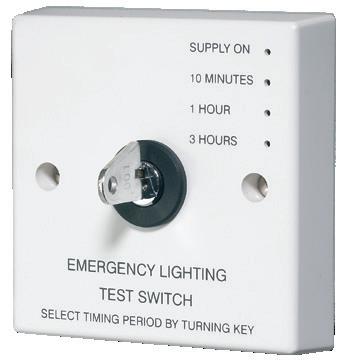
Overview
The Milan range of 15W circular LED Lumiaires offers a complete range of low profile polycarbonate IP65 light fittings. It is supplied as standard with selectable 3 colour temperature options, 3000K, 4200K & 6000K. The Milan range comes in a white finish as standard but is further enhanced with, black, chrome or brass coloured bezel options. The Milan range is further enhanced with the option of remote control testing on the emergency versions.
Features
• Selectable 3 colour temperature options 3000K, 4200K & 6000K
• Mains output 1400lm Emergency output 132lm
• Microwave with corridor function options
• Versatile multi-functional use, interior & exterior
• Tough polycarbonate housing
• May be mounted in any orientation
• Twist on diffuser
• Mains only & Maintained emergency options
• Minimal maintenance
• Easy installation
• IP65 ingress protection
• RoHS compliant
• Excellent luminaire spacings
Product Dimensions
Photometric Spacing Data 305mm dia.

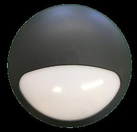
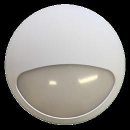
E/MILAN Milan LED 15W Mains Only Light
E/MILAN/M3/RC/LI Milan LED 15W 3hr Maintained Emergency Light – Remote Control Option
E/MILAN/M3/MW/RC/LI
15W
E/EM/RC Remote Control Option
E/MILAN/BEZ/CH Milan Chrome Bezel
E/MILAN/BEZ/BR Milan Brass Bezel
E/MILAN/BEZ/BK Milan Black Bezel
E/MILAN/EYE/WH Milan White Eyelid Bezel
E/MILAN/EYE/BK Milan Black Eyelid Bezel
Overview
The SoHo LED luminaire is a true 2D 28W replacement and boasts a high lumen output giving it a top tier market performance. Now with the added benefit of corridor function (microwave versions) and three colour temperature options, 3000K, 4200K & 6000K.
The Soho is also available with our optional remote control emergency testing function.
Finished with a white base and a high light transmission polycarbonate diffuser which is held securely in place by a single clip system. Now with benefit of corridor function, (microwave versions), colour change & remote control testing option on the emergency version.
Features
• SoHo Dimensions: 325mm dia.
• Mains Output: 2100lm, Emergency Output: 287lm
• Three colour temperature options
• Power consumption: 21W Circuit Watts
• Typical power saving: 35-40% over conventional 2D luminaires
• Now with ‘corridor function’ (microwave option only)
Now with corridor function, three colour temperature selection & remote control option
• The corridor function ensures that light is produced only when actually needed. This saves energy usage & possible light pollution
• When a person enters a corridor or room, the light will come on/increase to full brightness
• When the person leaves the corridor/room, a presence detector will dim the light after a pre-set period. After a further pre-set period, if no movement is detected the light will switch off completely
• The light also incorporates a daylight sensor so it only illuminates if the ambient light is below a pre-set level
The setting available are:
Distance (sensitivity) setting – The detector has a maximum range of 10M. Distance detected range can be adjusted to 100%, 75%, 50% & 0% of the maximum range (approx 6m radius mounted at 3m height).

• IP65
• Weight: 1.45 Kg
• Mains or emergency 3 hour maintained and microwave options available
• Compliance: BS EN 60598-2-22
• 3 colour temperature selection, 3000K, 4200K & 6000K
Hold Time Setting – The ‘Hold time’ is the period the lamp remains at 100% once movement has ceased. The sensor can be adjusted to 5s, 30s, 60s, 5min, 10min, 20min and 30min.
Daylight Setting – Day light value can be adjusted to 2 lux, 10 lux, 50 lux and disabled. If you choose ‘Disabled’ then the light will operate all the time no matter how bright the ambient light level is.
Stand-By Period (corridor function) – This is the time period the light will remain at the dimmer light level. Once the chosen time has elapsed the light will turn off. This can be over ridden so the light remains at the dimmed level until movement is detected.
Stand-by Dimming Level – This is the level the light dims to once movement has ceased & the hold time setting has elapsed, this can be set to 10%, 20%, 30% or 50% of the full light level. Choice of three colour temperatures, 3000k, 4200k & 6000k.
E/SOHO SoHo 21W Mains Version, 2100lm
E/SOHO/MW SoHo 21W Mains Complete with Microwave Sensor , 2100lm – Corridor Function
E/SOHO/M3/RC/LI
E/SOHO/M3/MW/RC/LI
E/EM/RC* Remote Control Option
SP/SOHO/M3/ST SoHo 21W Mains 3hr Emergency Version, 2100lm
SP/SOHO/M3/MW/ST 21W Mains 3hr Emergency Version Complete with Microwave Sensor, 2100lm – Corridor Function (Self Test, made to order.)
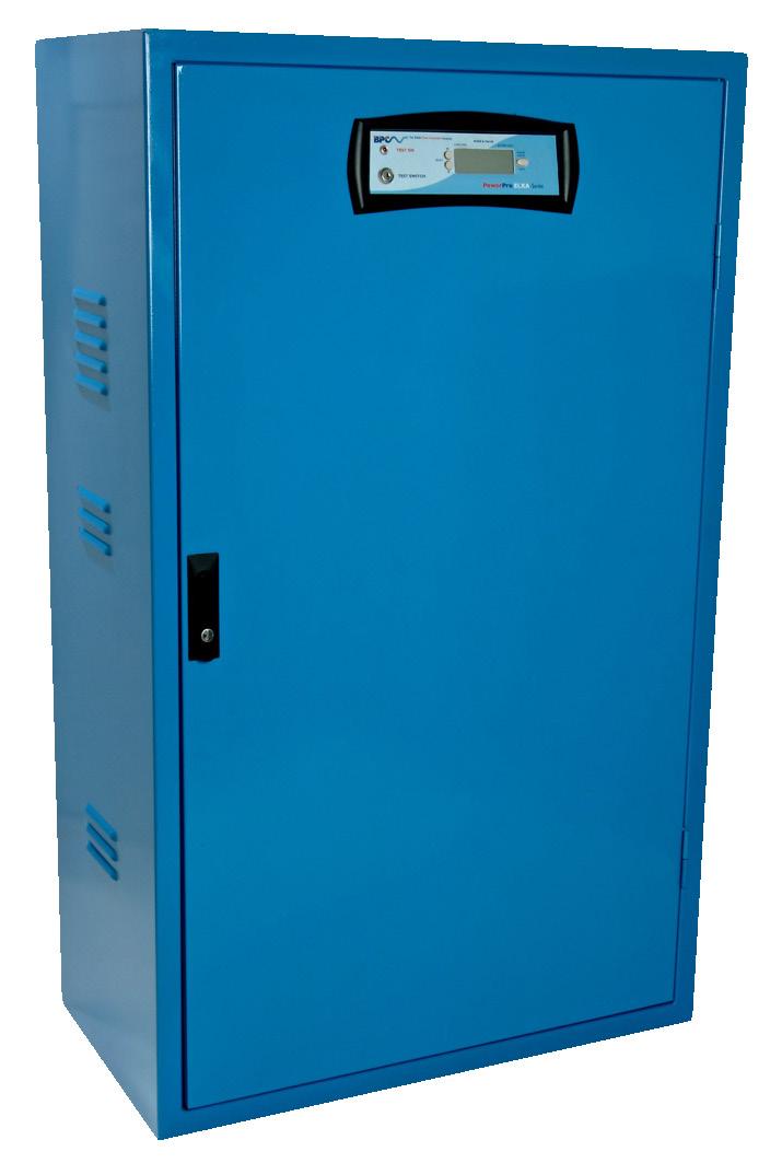
Overview
All Channel Safety Central Battery Units (CBU) are bespoke designs with a range of standard features and benefits providing a robust solution to meet specific customer requirements, supplied in wall mounted and free standing cabinets with options for high ingress protection.
Features
• Bespoke designs
• Ventilated mild steel cabinets
• Maintained and Non-Maintained options available
• 12/24/36/48/50/110/220V DC output options
• Extensive range of Slave Luminaires available
• Various back up runtimes to suit specifications
• Options for self-contained battery compartments
Overview
AC/DC Central battery units require the use of special lights known as ‘slave fittings’.
The slave fittings obtain their emergency power supply from a separate central bank of batteries. The central battery system makes maintenance and testing easier, and fittings are available in 24V, 50V, 110V and 230V AC/DC.
Features
As the name implies a central battery emergency light is one where it’s power comes from one source. The central battery slave fittings do not have an integral battery but rely on the central battery to supply them.
Central battery systems come in either maintained or nonmaintained. They must be wired in fire rated cables.
The Stratos range of slave fittings offers a slimline profile in contemporary design. Each light is supplied with a legend pack as standard. Optional drop down exit blades and semi-recessing kits are available.
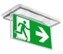
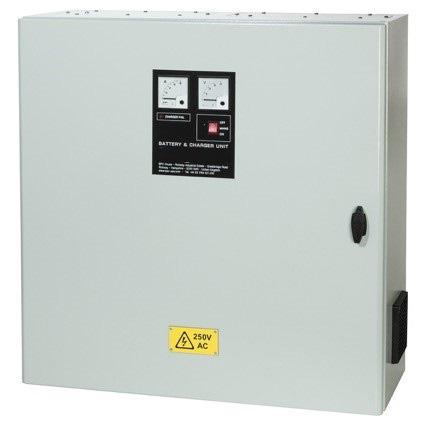
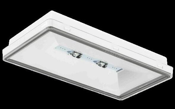
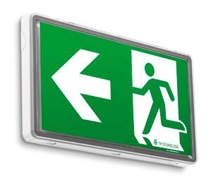
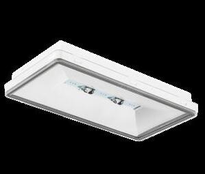
E/STRATOS/24
E/STRATOS/50
E/STRATOS/110
Stratos 7x LED – 1W, IP65, 24 V AC/DC slave bulkhead C/W exit sign pictogram (1W 198lm IP65)
Stratos 7x LED – 1W, IP65, 50 V AC/DC slave bulkhead C/W exit sign pictogram (1W 198lm IP65)
Stratos 7x LED – 1W, IP65, 110 V AC/DC slave bulkhead C/W exit sign pictogram (1W 198lm IP65)
E/STRATOS/230 Stratos 7x LED – 1W, IP65, 230 V AC/DC slave bulkhead C/W exit sign pictogram (1W 198lm IP65)
E/STRATOS/REC/KIT Stratos Semi Recessing Kit
E/STRATOS/PIC/KIT Stratos Hanging Blade legend C/W exit sign pictogram
Overview
The STI-LED range of Mini Static Inverters have been engineered with the LED lighting market in mind offering a cost effective solution to powering unmodified LED luminaires in the event of mains failure the unit is a pure sine wave inverter with a 230V AC output.
Features
• Pure Sine Wave
• 32 bit Micro-controller
• Multi Function LCD Display
• 3 Hour Duration
• Overload & Short Circuit Protection
• Complete with in-built hold off relays
Cubicle
x 472 x 166
Cubicle N/A
Inverter Cubicle
x 472 x 166
Cubicle
x 472 x 174
Inverter Cubicle
x 472 x 166
Cubicle (x2)
x 472 x 174 C/STI-LED-800
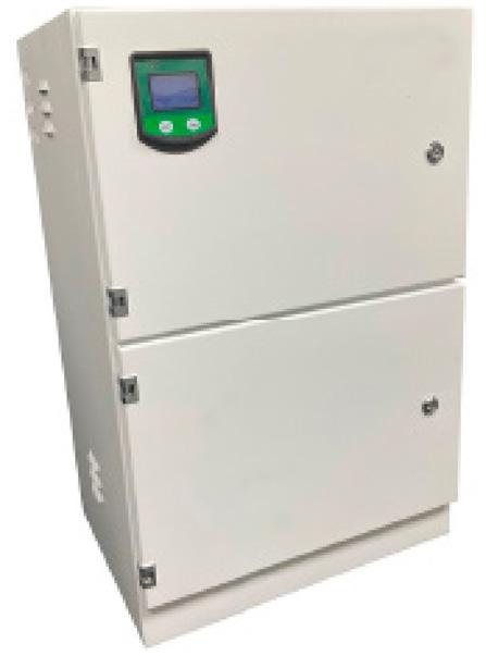
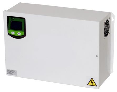
Inverter Battery Cubicle
x 500 x 380
Overview
The PowerPro EL Ranges are Static Inverter Systems designed specifically for emergency lighting applications according to European BS EN50171 specification.
A highly versatile range, not only providing capacity up to 160kVA Allowing Channel to provide an all-inclusive selection of reliable and cost effective products to meet the most challenging of lighting applications.
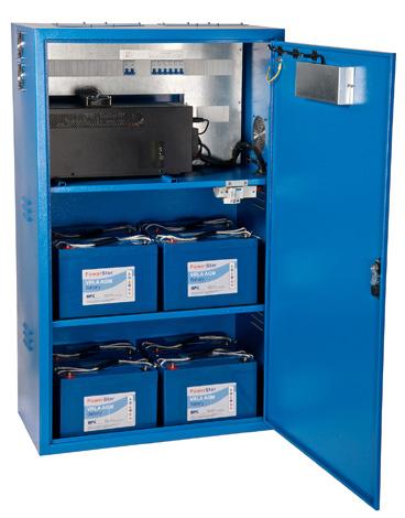
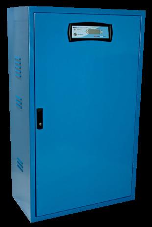
Features
• Remote Alarm Panel – External panel for monitoring the static inverter
• Output Distribution – Internal distribution of the lighting circuits, standard in EL100XA & EL100, multiple outputs are optional
• Maintenance Bypass Panel – to provide flexibility during maintenance, service and/or repairs to the equipment. The bypass can ensure that the system is isolated from the critical load whilst work can be carried out
• Phase Failure Monitoring – Factory fitted relays to ensure that the system monitors all three phases. Failure of any phase activates the emergency lights.
• Sub-Circuit Monitoring – Factory Fitted relays monitor external lighting circuits, if any of the external circuits fail the emergency lights are activated
• Lighting Control Interface – Allows communication via a node/module to the testing and monitoring systems.
• Fire Alarm monitoring – An alarm condition from the fire alarm panel will activate the emergency lights
• Night-Watchmen Switch – Enables switching of the emergency lights from a remote location, fail safe in an emergency condition
• Timer Control – Solar dials or 24hour timers can be used to activate the non-maintained contractor.
• Earth Fault Alarm – Monitoring of battery positive and negative for earth leakage
Our Static Inverter Systems are able to provide the following input and output configurations:
• Single Phase Input : Single Phase Output
• Three Phase Input : Single Phase Output
• Three Phase Input : Three Phase Output
• On Mains failure, the system converts DC power from the central battery to AC output. Our systems allow the use of our modern energy efficient luminaires, while our on-line ‘NO BREAK’ inverter systems enable the use of high-pressure discharge lighting.
No-Break
We manufacture a “No-Break” Emergency Lighting Static Inverter System that guarantees there will be no changeover switching of the supply to the load on mains failure. The load is totally unaffected by supply variation and is constantly fed with stabilised, smoothed and conditioned power.
Static Inverter Systems for Emergency Lighting
A totally integrated, energy efficient cost-effective and unobtrusive solution for all Emergency Lighting situations:
• Passive Standby
• Active Standby
• No-Break for ALL lighting loads including high pressure discharge
• All systems can be configured 1:1, 3:1 or 3:3
• Integration with our complementary products for Emergency Lighting
• Optional output current limiters
Passive Standby
Our low cost flexible Passive Standby Static Inverter System is ideal for use with fluorescent and incandescent lighting sources. Traditional technology provides proven reliability with one of the lowest component counts in the industry. Low heat output, high efficiency (typically greater than 95% AC-AC).
Conforms with all current relevant harmonised European standards.
Static Standby
“Active Standby” is our constantly running, off load, Static Inverter which can be monitored for function at all times – reassuring to know that the system will work when an emergency load is applied.
Features
• In critical standby applications the battery can be a large integral part of the system and can also be an unpredictable element of the design
• Depending on models, batteries are either 3 to 5 year or 8 to 10 year design life. There are six key factors that can affect UPS battery life-the placement, ambient temperature, cycling, maintenance, battery chemistry and battery storage. It is important that sufficient maintenance is carried out to extend the life of your battery to the fullest
Features
• Channel Safety can offer a wide range of Small Office/Home Office related line interactive UPS products, designed to offer total power protection to a broad range of applications.
• Our PowerStar and PowerPrem+ ranges will provide clean and reliable backup power to ensure continued data integrity and optimum performance under a wide range of mains power conditions.
Available from 650VA – 3kVA
• Fully intelligent line interactive
• Microprocessor based design
• Overload protection
• Boost & buck AVR voltage stabilisation
Available from 800VA – 5kVA
• Microprocessor-based line interactive technology
• Built-in boost and buck AVR
• Tower and rackmount convertible design (1-3kVA)
• Hot swappable battery design (1-3kVA)
Available from 1kVA – 3kVA
• Digital Signal Processor (DSP) technology
• Tower and rackmount convertible design
• Hot swappable battery design
• Multiple communication ports
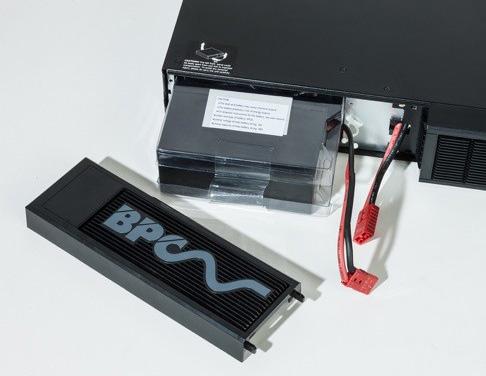

Features
• Superb recovery from deep discharge
• Electrolyte suspension system
• Gas recombination/Multipurpose: float or cyclic use
• Superior energy density/Visible status indication
• Lead calcium grids for extended life
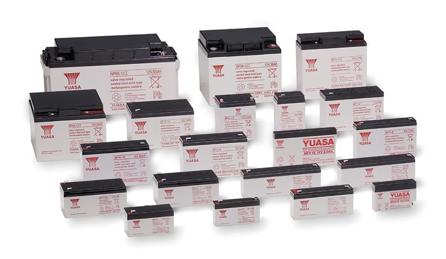
Sealed Lead Acid Batteries
B/12V/0.8AH/SLA 12 Volt 0.8Ah sealed lead acid battery (1 block)
B/12V/1.2AH/SLA 12 Volt 1.2Ah sealed lead acid battery (1 block)
B/12V/2.1AH/SLA 12 Volt 2.1Ah sealed lead acid battery (1 block)
B/12V/2.3AH/SLA 12 Volt 2.3Ah sealed lead acid battery (1 block)
B/12V/2.8AH/SLA 12 Volt 2.8Ah sealed lead acid battery (1 block)
B/12V/3.2AH/SLA 12 Volt 3.2Ah sealed lead acid battery (1 block)
B/12V/4AH/SLA 12 Volt 4Ah sealed lead acid battery (1 block)
B/12V/7AH/SLA 12 Volt 7Ah sealed lead acid battery (1 block)
B/12V/12AH/SLA 12 Volt 12Ah sealed lead acid battery (1 block)
B/12V/17AH/SLA 12 Volt 17Ah sealed lead acid battery (1 block)
B/12V/24AH/SLA 12 Volt 24Ah sealed lead acid
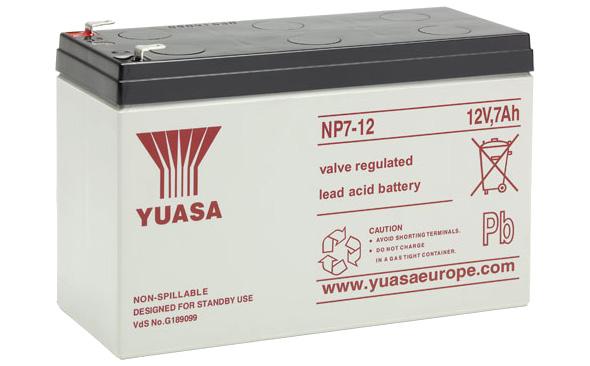
(1 block)

A Guide to Emergency Lighting
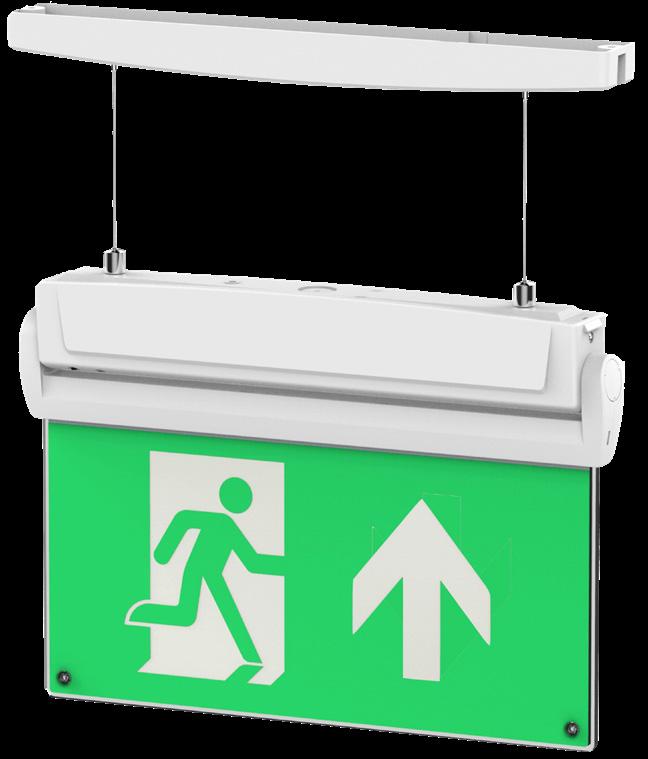
Lighting makes up approximately 20% of the UK’s energy consumption and non-domestic lighting shamefully accounts for approximately 24 million tonnes of CO2 per annum.
As we all know, LED technology is rapidly taking over the lighting business, providing not only an attractive alternative to its conventional counterparts but also proving to provide long term savings in energy and suBS equent replacement costs.
In addition to energy savings, LEDs in general illumination applications provide longer operating life (in the region of up to 50,000 hours), directionality, compact size, ease of control and dimmability compared to incumbent technologies they replace.
Contractors should be advising about the benefits of LED lighting solutions...
The LED has many benefits that should be highlighted to customers during a site survey, such as:
Reduced air conditioning costs as LED lights have a lower heat output LED lights last longer than conventional lighting. They create less waste and boast more easily recycled components Cost saving over a longer period of time The LED pros outweigh the cons when it comes to choosing efficient, cost effective lighting solutions for commercial, residential or industrial properties.
The British Standard BS 5266 has been revised to conform with the European Standard EN1838 (issued in the UK under reference BS EN1838/BS 5266 Part 7) which specifies luminous requirements for emergency systems installed in premises. It also now calls up the luminaire product standard BS EN60598-2-22.
An escape lighting luminaire complying with EN 60598-2-22 shall be sited to provide appropriate illuminance near each exit door and at positions where it is necessary to emphasise potential danger or safety equipment. The positions to be emphasised shall include the following:
• At each exit door intended to be used in an emergency
• Near stairs so that each flight of stairs receives direct light Near any other change in level
• Mandatory emergency exits and safety signs
• At each change of direction
• At each intersection of corridors
• Outside and near to each final exit
• Near first Aid Post
• Near fire fighting equipment
• Near escape equipment for the disabled
• Near disabled refuge and call points
• Safety signs shall be illuminated to at least 50% of the required luminance within 5 seconds and full required luminance within 60 seconds.
• The colours shall conform to the requirements of ISO 3864.
• The luminance of any area of safety colour of the sign shall be at least 2 cd/m2 in all relevant viewing directions.
• The ratio of the maximum to the minimum luminance within either white or the safety colour shall be not greater than 10:1.
• All signs must be of the same type within a building and not mixed
For further information review the Technical Statement published by ICEL (ICEL TS03 Issue 1 – 12/12) on Emergency Exit “Clear” Signs.
Emergency Escape Lighting
To provide visibility for evacuation purposes lighting is required in the volume of the space. In this standard the recommendation is filled by the mounting of luminaires at least 2m above the floor. Signs which are provided at all exits intended to be used in an emergency and along escape routes shall be illuminated to indicate unambiguously the route of escape to a point of safety. Where direct sight of an emergency exit is not possible, an illuminated directional sign (or series of signs) shall be provided to assist progression towards the emergency exit.
An escape lighting luminaire complying with EN 6059-2-22 shall be sited to provide appropriate illuminance near each exit door and at positions where it is necessary to emphasise potential danger or safety equipment.
The positions to be emphasised shall include the following (see below):
• At each exit door intended to be used in an emergency
• Near stairs so that each flight of stairs receives direct light
• Near any other change in level
• Mandatory emergency exits and safety signs
• At each change of direction
• At each intersection of corridors
• Outside and near to each final exit
• High risk task areas
Various specific locations now require additional emergency illumination:
5 Lux Refuge Areas, Panic Bars, Swimming Pool Areas
15 Lux Kitchens, First Aid Rooms, Plant Rooms, Fire Alarm Control Equipment, Reception Areas
50 Lux Treatment Rooms
Escape Route Lighting
• For escape routes up to 2m in width, the horizontal illuminances on the floor along the centre line of an escape route shall be not less than 1 Ix and the central band consisting of not less than half of the width of the route shall be illuminated to a minimum of 50% of that value.
Open Area (Anti-Panic) Lighting
• The horizontal illuminance shall be not less than 0.5 Iux at the floor level of the empty core area which excludes a border of 0.5m of the perimeter of the area.
• High risk task areas
Building Regulations
To ensure specified luminaires meet the requirements of the current building regulations it is important to consider the legislation contained within the Building Regulations. The most relevant of these are:
Approved Document B
• Approved Document B (Fire safety) – Volume 1: Dwellinghouses (2006 Edition)
• Approved Document B– Volume 2: Buildings other than dwellinghouses (2006 Edition)
Part B deals with the fire safety requirements for emergency lights and the use of thermoplastic materials.
It is our recommendation that reference be made to the latest version of the Approved Documents. Full details can be found on: www.planningportal.gov.uk
Approved Document L
• Approved Document L1A: Conservation of fuel and power (New Dwellings) (2006 Edition)
• Approved Document L1B: Conservation of fuel and power (Existing Dwellings) (2006 Edition)
• Approved Document L2A: Conservation of fuel and power (New buildings other than dwellings) (2006 Edition)
• Approved Document L2B: Conservation of fuel and power (Existing buildings other than dwellings) (2006 Edition)
Part L requires that energy efficient lighting is installed in both domestic and non-domestic dwellings, existing, new & refurbished (over 100m2).
Part L gives design information for the following (non-domestic dwellings):
• Selection of lamp types
• Effective use of daylight
• Control gear & power factor correction
• Use of lighting controls
• Luminaire efficiency
The International Protection code, commonly known as the Ingress Protection code (IP) indicates the protection afforded by an enclosure against the ingress of foreign (solid) bodies and ingress of moisture and liquids. The IP rating also classifies the protection given by an enclosure against touching live or moving parts.
The IP rating is given by the use of two numbers.
First Digit - Protection Against Ingress of Solid Objects Second Digit - Protection Against Ingress of Liquids
0 No protection
1 Protection against large sized bodies such as hands
2 Protection against medium sized bodies such as fingers
3 Protection against small sized bodies 2.5mm dia. or larger such as tools & wires
4 Protection against very small sized bodies 1mm dia. or greater
5 Protection against harmful deposits of dust (Dust proof)
6 Complete protection against deposits of dust (Dust tight) 0 No protection 1 Protection against vertically falling drops of water 2 Protection against drops of water up to 15° from the vertical
against rain falling up to 60° from the vertical
against splashed water from any angle
Protection against jets of water from any angle
against water from heavy seas
Protection against immersion for a defined period
Protection against immersion for an indefinite period

Features
Attractively designed in tough ABS plastic, the I/CHIL/PL1 portable induction loop system is a truly portable and extremely durable audio frequency induction loop system, packed full of features and available at a very competitive price. Fully compliant with BS 7594 and EN60118-4, it is ideal for use in schools, shops, nursing homes, leisure centres, hotels, banks, GP surgeries, reception desks and many other private, public and civic applications.
• Indicators provided for power on, input level, charging required and charging in progress
• I/CHIL/PL1 kit includes PL1 amplifier, plugtop charger, “induction loop available” sticker and wall bracket
• I/CHIL/PL3 kit includes PL1 amplifier complete with battery & integral microphone, plugtop charger and ‘AFILS available’ sticker
• Dimensions: 300mm (H) 250mm (W) 100mm (D)
• FPROK1 kit includes Fosmeter Pro, 1 x Audio Signal Generator, 2 x protective pouch, 1 x 32 ohm headphones for FPRO, 2 x 9 V battery
• Ideal for restricted person to person contact in areas such as banks, post offices, small meeting rooms, reception desks, open plan offices and ticket booths
• Battery Internal 12V VRSLA (Valve Regulated Sealed Lead Acid)
• Weight: 1.7Kg
Induction Loop Kits
I/CHIL/PL1 Portable induction loop system
I/CHIL/PL3 Portable induction loop system complete with carry case
Testing Equipment
I/CH/FPROK/1
Signs & Stickers
I/CH/PIL/L
Fosmeter Pro Induction loop test kit complete with signal generator
Desktop portable induction loop display sign
Features
The ML1/K counter induction loop kit is ideal for use in post offices, banks, building societies, ticket offices and reception areas. Comprising a compact wall-mounting double gang induction loop amplifier, a self-adhesive microphone and pre-formed counter loop, it can generate a loop listening field of 1.5m2 approx. making it ideal for counters, desktops and tables.
• Attractively-packaged kit includes:
• 1x I/CHIL/ML1 wall-mounting induction loop amplifier, 1x I/CHIL/AMT self-adhesive microphone, 1x I/CHIL/TX2 pre-formed counter loop & 1x I/CHIL/TEAR ‘loop fitted’ sticker
• Double-gang wall-mounting I/CHIL/ML1 amplifier fits standard 25mm back boxes and is ideal for mounting under desks, counters or table tops
• Fully compliant with EN60118-4 (formerly BS 6083) and BS 7594:1993
• Installer-friendly design requires no specialist audio experience or connectors – the ML1 can be fitted by any competent electrician
• Can be used to help building managers and service providers comply with BS 8300, the Equality Act and the Care Standards Act
• Dimensions 143mm(H) 83mm(W) 32mm(D)
• Weight 300g (amplifier only)
Counter Top Kits
I/CHIL/ML1/K Counter induction loop kit
I/CHIL/ML1 1.5m2 wall mounting double gang
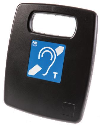
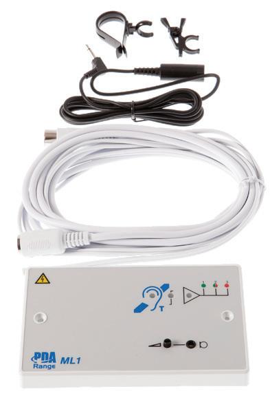
Features
A range of current mode induction loop amplifier designed to meet or exceed the requirements of BS7594 and EN60118-4 when correctly installed. Ideal for the following applications:
• Meeting rooms
• Lecture theatres
• Shops • Churches • Schools • TV lounges
Induction Loop Amplifier Kits
1.5m2 Counter Induction Loop Amplifier Kit
• Health and fitness club
• Other small to medium sized applications
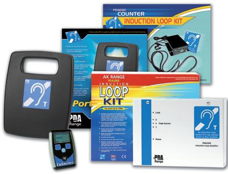
I/CHIL/103C Counter hearing loop kit with PDA 103 amplifier, AMT microphone and TX2 counter loop
50m2 Induction Loop Amplifier Kits
I/CHIL/103L Small room induction loop kit complete with AMT tie/desk microphone, 30m of loop cable and x2 induction loop stickers
I/CHIL/103R Small room induction loop kit complete with APM omni-directional plated microphone, 30m of loop cable and x2 induction loop stickers
Pda 200e Amplifier
I/CHIL/200E 200m2 Wall mounted loop amplifier
200m2 Induction Loop Amplifier Kits
I/CHIL/K1 Meeting room loop induction kit complete with 1x I/CHIL/200E, 1x I/CH/APM plated microphone and 1x loop fitted sticker
I/CHIL/K2 Lecture room loop induction kit: complete with 1x I/CHIL/200E, 1x I/CH/AMT tie/desk microphone, 1x I/CH/AML lectern microphone, 2x I/CH/APJ outreach plates and 1x loop fitted sticker
I/CHIL/K3 TV & music room loop induction kit complete with 1x I/CHIL/200E, 1x I/CH/AMH handheld microphone, 1x I/CH/APS scart lead, 1x I/CH/APJ outreach plate, 1x I/CH/APL outreach plate, 1x loop fitted sticker
Testing Equipment
I/CH/FPROK/1 Fosmeter Pro Induction loop test kit complete with signal generator
Professional Induction Loop Phase Shifting Amplifiers
PDA/S Phase Shifting Dual Hearing Loop Amplifiers
Type S – Standard perimeter loops for large areas
I/CHIL/5/SD “200m2 free-standing PDA/S hearing loop amplifier, 4.75A”
I/CHIL/5/SW “200m2 wall-mounting PDA/S hearing loop amplifier, 4.75A”
I/CHIL/7/SD “500m2 free-standing PDA/S hearing loop amplifier, 7.5A”
I/CHIL/7/SW “500m2 wall-mounting PDA/S hearing loop amplifier, 7.5A”
I/CHIL/11/SD “1000m2 free-standing PDA/S hearing loop amplifier, 11A”
I/CHIL/11/SW “1000m2 wall-mounting PDA/S hearing loop amplifier, 11A”
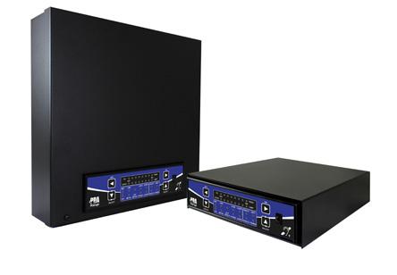
PDA/D Phase Shifting Dual Hearing Loop Amplifiers
Class D output
Type D – phase shifted amps for low overspill and large areas
I/CHIL/PDA5/DD "200m2 free-standing PDA/D phased-shifting hearing loop amplifier, 2 x 3.25A"
I/CHIL/5/DWA "200m2 wall-mounting PDA/D phased-shifting hearing loop amplifier, 2 x 3.25"
I/CHIL/7/DD "500m2 free-standing PDA/D phased-shifting hearing loop amplifier, 2 x 5A"
I/CHIL/7/DW "500m2 wall-mounting PDA/D phased-shifting hearing loop amplifier, 2 x 5A"
I/CHIL/11/DD "1000m2 free-standing PDA/D phased-shifting hearing loop amplifier, 2 x 7.5A"
I/CHIL/11/DW "1000m2 wall-mounting PDA/D phased-shifting hearing loop amplifier, 2 x 7.5A"
Features
Any PDA range amplifier marked with the ‘Outreach Compatible’ symbol is compatible with our unique Outreach Plate audio input extension system. This system allows the connection of multiple microphone or line level inputs via a range of single gang connector plates. Carefully designed to cover the most common variants of audio connector (including XLR line, XLR mic., 3.5mm jack, dual phono and 1/4” jack), a maximum of 10 outreach plates (any mix) can be daisy chained to an amplifier’s Outreach socket using standard two pair audio cable such as Belden 8723 (or equivalent).
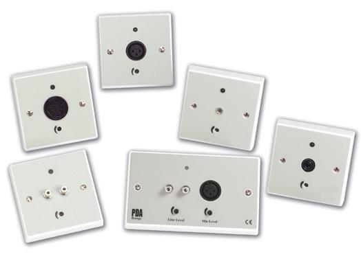
I/CH/APJ 3.5mm mono jack plate for connection of CH/AMT, CH/AMH, CH/AML or CH/AMD microphones
I/CH/APL Dual phono line level audio plate for connection of CH/APS SCART lead or other line level audio feeds
I/CH/APQM 6.35mm stereo jack plate for connection of CH/AMR/L or H radio mic.
I/CH/APQL 6.35mm stereo jack plate for the connection of line level feeds from mixing desks, etc.
I/CH/APXM XLR mic level plate for connection of CH/AMP microphone
I/CH/APXL XLR line level plate for connection of mixing desk line level feeds
I/CH/APM Omni – directional plated microphone for wall/ceiling/desk mounting
I/CH/BELDEN/25 25m of Belden 8723 audio cable
I/CH/FLAT/2005 100m x 1.0mm copper tape (flat loop)
I/CH/FLAT/3005 100m x 1.5mm copper tape (flat loop)
Please note:
I/CHIL/PL1 and I/CHIL/DOM amplifiers do not have outreach sockets. I/CHIL/MK1 amplifier can have a maximum of three outreach plates connected to it.
Features
These microphones have the highest tolerance of magnetic feedback and are therefore recommended for induction loop systems. Dynamic microphones should not be used as they contain moving coil magnets which can be affected by the magnetic field generated by the loop.
Phantom power is provided on all Induction Loop amplifiers, so the microphones with internal batteries are not necessary. To avoid interference, microphone cables should be sited at least one metre away from loop cable.
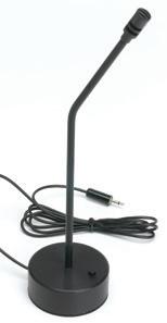
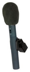
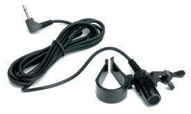
I/CH/AMP Professional handheld microphone for CHIL/200E or CH/APXM plate (requires CH/AXLR lead)
I/CH/AMR Levalier radio microphone complete with microphone, receiver, transmitter, PSU. Connects to CHIL/200E or CH/APQM outreach plate
I/CH/APM Omni directional plated microphone for wall/ceiling mounting. Connects to CHIL/ML1, CHIL/102, CHIL/200E
I/CH/AMD Desktop microphone for CHIL/ML1, CHIL/DOM, CHIL/102, CHIL/200E, CHIL/PL1 or CH/APJ outreach plate
I/CH/AML Lectern microphone for CHIL/ML1, CHIL/DOM, CHIL/102, CHIL/200E, CHIL/PL1 or CH/APJ outreach plate
I/CH/AMR/H Handheld radio microphone C/W mic, receiver, transmitter, psu. Connects to CHIL/200E or CH/APQM outreach plate
I/CH/AMT Tie/desk microphone for CHIL/ML1, CHIL/DOM, CHIL/102, CHIL/200E, CHIL/PL1 or CH/APJ outreach plate
I/CH/PRO45 High Quality hanging ambient microphone
I/CH/FLAT/2005 100m x 1.0mm copper tape (flat loop)
I/CH/FLAT/3005 100m x 1.5mm copper tape (flat loop)
Please note: All microphones supplied with a connection lead except I/CH/AMP. If using an AMP, a range of connection leads are available.
Features
The Hark Help and Assistance Response Kit is simple to install and provides peace of mind wherever an indication of ‘assistance required’ is called for. Meeting the BS Standard requirement for all disabled toilets to be fitted with an emergency toilet alarm.
Available in kit solutions finished in white or stainless steel, to fit discretely into any decor or environment.
The unit benefits from a reassuring audible sound from within the reset unit which confirms that assistance is on the way in addition the unit has braille text.
• Only 3 points to install on a standard system, and can be simply linked and expanded to other systems
• Simple to expand as requirements increase
• Sounder within the reset unit to give audible reassurance that assistance is on the way
• Kits supplied with Twin pull cord rings, Braille text on the reset unit as well as a Disabled Persons sticker
• Multi-way remote indicator units available
• Assists in compliance with the DDA, BS 8300 and other care standards
• Suitable for commercial and public buildings as well as specialist areas such as hospitals, restaurants, nursing and retirement homes
• Call acknowledge on Hark+
Additional Options
The Help Alarm Response Kit can be linked to a remote multi-way indicator panel (for use in a reception or staffed area).
A 12 volt relay unit can be used to interface the unit to a wide range of equipment such as:
• BMS
• Fire alarms
• Intruder Alarms
• Paging transmitters
Additional pull cord units can be added to the system to allow for larger rooms or multi area coverage. Please note that additional pull cords will operate and be reset by the same unit as the initial pull cord.
The Indicator Units are simple to install and meet the BS requirement for all disabled toilets to be fitted with an emergency toilet alarm. 75 db at 1metre.
These units can be purchased as either 1 or up to 11 indicators and come finished in either White Polycarbonate or Stainless Steel. Custom engraving is available.
Push Button
The HARK Push Button can be used instead of a hanging pull cord to notify that the user is in distress.
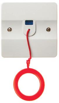
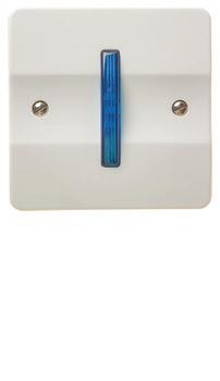
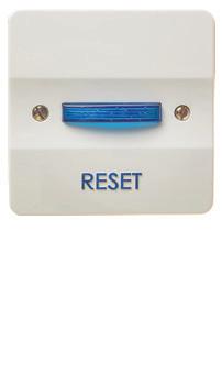
The pull cord unit is supplied with a red plastic ring. An extra ring is supplied to conform to ‘Approved Document M’. The second ring should be fitted lower down near floor level. Activating a call is simply made by pulling the cord. This will activate the re-assurance indicator on the pull cord unit. In turn this will also illuminate the reset unit and trigger the internal sounder. At the same time the Overdoor indicator/sounder unit will illuminate and trigger it’s own internal sounder.
The reset unit has a blue engraved legend ‘RESET’. When a call is activated the reset switch illuminates and the internal sounder activates. The call is reset by simply pressing the reset switch. The reset switch is supplied with Braille legend on the switch piece.
The Overdoor indicator/Sounder unit is supplied with an integral Power supply unit. A fused spur should be fitted nearby and wired to this unit to provide power. The unit will illuminate and sound as soon as a call is activated. The unit will cease once the reset switch is pressed.
HARK includes a variety of different accessories to work in compliance for a professional end result.
These accessories combine modern aesthetics and high functionality providing you with the ideal solution for the most demanding installations. HARK assists with compliance with the DDA, BS 8300 & other care standards.
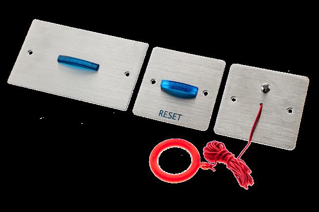
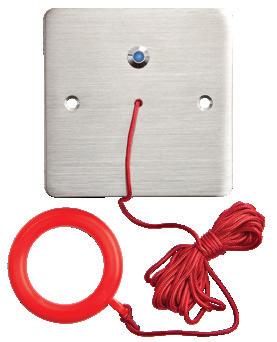
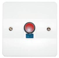
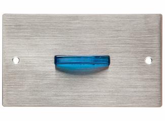
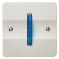
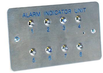
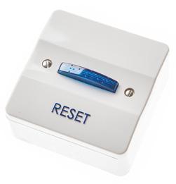
N/HARK/1
N/HARK+
Push Button
Complete kit with pull cord, reset, PSU/ Indicator
Stainless steel option complete with battery back up (battery included) & Call Acknowledge option
N/HARK/1/PB HARK 1 push button
N/HARK+/PB/SS HARK Stainless Steel Push Button
Pull Cords
N/HARK/1/PC HARK 1 pull cord
N/HARK+/PC/SS HARK pull cord stainless steel
Power Supply/Indicator Units
N/HARK/1/PSU HARK 1 power supply unit
N/HARK+/PSU/SS HARK power supply unit stainless steel
N/CHWB/BN/12V/DB Sounder Beacon
Reset Units
N/HARK/1/RS HARK 1 reset unit
N/HARK+/RS/SS HARK reset unit stainless steel
Indicator Units, Panels and Accessories (Special Engraving Available P.O.A)
N/HARK/RI/1 HARK 1-way indicator unit
N/HARK/RI/1/SS HARK 1-way indicator unit stainless steel
N/HARK/RI/2 HARK 2-way indicator unit
N/HARK/RI/2/SS HARK 2-way indicator unit stainless steel
N/HARK/RI/3 HARK 3-way indicator unit
N/HARK/RI/3/SS HARK 3-way indicator unit stainless steel
N/HARK/RI/4 HARK 4-way indicator unit
N/HARK/RI/4/SS HARK 4-way indicator unit stainless steel
N/HARK/RI/5 HARK 5-way indicator unit
N/HARK/RI/5/SS HARK 5-way indicator unit stainless steel
N/HARK/RI/6 HARK 6-way indicator unit
N/HARK/RI/6/SS HARK 6-way indicator unit stainless steel
N/HARK/RI/7 HARK 7-way indicator unit
N/HARK/RI/7/SS HARK 7-way indicator unit stainless steel
N/HARK/RI/8 HARK 8-way indicator unit
N/HARK/RI/8/SS HARK 8-way indicator unit stainless steel
N/HARK/RI/9 HARK 9-way indicator unit
N/HARK/RI/9/SS HARK 9-way indicator unit stainless steel
N/HARK/CA Call Acknowledge Button on remote indicators (Hark+ ONLY)
Overview
Quantec is a powerful yet easy to use addressable call system that helps ensure vital communication throughout a building.
The way the system operates can be tailored to suit a care facility’s specific requirements with different day, night and call divert arrangements easily accommodated to meet the exact operational needs and precise layout of any building. This flexibility, coupled with many advanced features such as multiple call levels and full monitoring of all network devices, makes Quantec the obvious choice for larger nursing homes.
Features
• Multiple call levels including standard, en suite, help required, emergency, attack, presence & attendance
• Tailored to suit a site’s exact operational requirements
• Call accept feature & Automatic call divert
• Illuminates overdoor lights and corridor lights
• Staff attendance allows staff entering rooms to log their ‘attendance’ via an infrared call point or ceiling receiver
• Call follower sounders (optional)
• Night mode allows Quantec to work in a totally different way at night, providing for fewer staff and reduced sound levels
• Infrared staff protection helps protect staff against disturbed patients, intruders and aggressive visitors
Quantec – Typical System Architecture
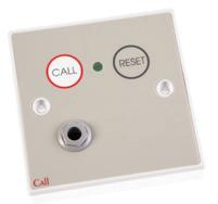
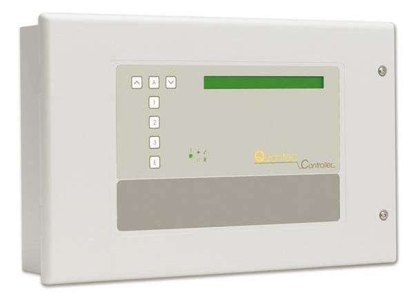
• ‘Surveyor’ data analysis software allows the outputting of custom reports
• Optional paging facilities (DECT telephone capability also available)
• Laptop programmable system controller
• Minimising disturbance, with no expensive rewiring
• Easy to install & expand
• Low maintenance time and costs
• A cost-effective expansion kit that adds true BS 8300 compliant accessible toilet alarm functionality to a Quantec Addressable Call System (order code N/ QT951)
1000s of Sites are Benefiting from the Quantec Addressable Call System...


Panels
N/QT601-2
Quantec addressable nurse call panel (requires x2 B/12V/7AH/SLA batteries)
N/CH385 Flush bezel for Quantec QT601-2
B/12V/7AH/SLA 12 Volt 7Ah sealed lead acid battery (1 block)
Display Units
N/QT608C Quantec display unit with controls
N/QT608CD Quantec display unit with no controls
Call Points
N/QT602 Quantec call point with reset button (remote socket)
N/QT602R Quantec call point with reset button and I/R receiver (remote socket)
N/QT602M Quantec magnetic reset/call unit (remote socket)
N/QT609 Quantec call point with reset button (no remote socket)
N/QT609RS Quantec call point with reset button and I/R receiver (no remote socket)
Door Monitoring Stations
N/QT604 Quantec door monitoring station with reset button
Over Door Lights
N/QT606 Quantec slave overdoor light
N/QT606A Quantec addressable overdoor light
Addressable Sounders
N/QT688/2 Quantec high output addressable sounder
Pull Cord
N/QT607 Quantec ceiling pull cord unit
Tail Lead
N/CH/805C/6 6ft (1.8m) tail call lead
N/CH/805/14 14ft (4.2m) tail call lead
Magnetic Reset Key
N/CH/803M Magnetic reset key complete with keyring
Dual Action Transmitter
N/QT412RXA Dual action infra-red/radio transmitter (push for attack/pull for attack)
N/QT423 Configurator for N/QT412RXA
N/QT611 Universal interface (call unit)
Infra-Red Ceiling Receivers
N/QT302RX Quantec master infra-red ceiling receiver
Portable Receiver
N/QT1001/S Quantec portable receiver (pocket data pager)
Network Splitter
N/QT603 Network splitter, 5 outputs – up to 60 addressable devices per splitter
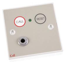
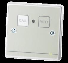
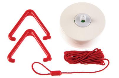
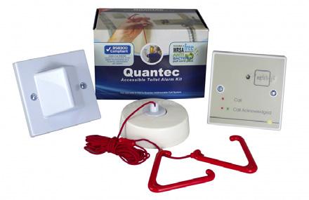
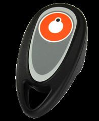
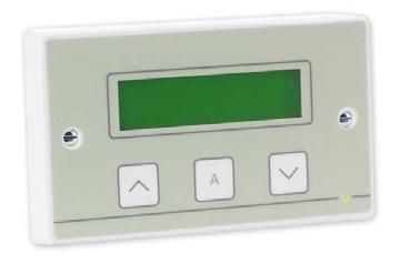
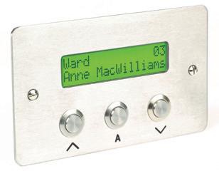
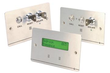
Overview Designed in conjunction with an NHS Trust widely regarded as the leading light in the provision of high-intensity dementia care, Quantec Dementia Care products allow care providers to enhance the level of care they provide for patients suffering from Dementia, Alzheimers, Incontinence and other degenerative illnesses.
The system is engineer programmable to suit the exact requirements of an individual patient/bedroom and includes all of the inputs, outputs, timers and power needed for the connection of PIR movement sensors, enuresis sensors, bed exit mats, low voltage LED lighting, door monitoring contacts, slave infrared ceiling receivers, slave controllers, overdoor lights, room status controllers and more. The controller comes with a number of pre-set DIP-switch selectable configurations, all geared towards giving patients the freedom and dignity they need to live their lives as normally as possible with as little intervention from carers as their condition will allow.
Features
• Can be configured to automatically switch lights on and off when movement is detected to safely guide patients to and from ensuite areas
• Provides clear and concise indication of room status data at ALL relevant Quantec displays (e.g. Bedroom 1, Bed Exit)
• All room/patient call activity is logged at the main Quantec Controller for optional output to our Quantec Surveyor data management software
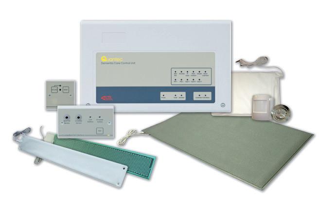
• Comes with 10 pre-set patient monitoring configurations including: high-intensity, medium-intensity and ensuite ushering
• Can be easily adapted to the changing needs and ongoing behaviour patterns of Dementia and Alzheimers sufferers
• Many of the components shown can be easily added to existing Quantec systems
• All network devices are designed and manufactured in the UK
Mains supply 230V A.C 50/60Hz. Max. current 350mA
Internal Power Supply 27V DC (nominal)
Max. Switching Current 25mA
Max. Switching Voltage 30V DC
Main Fuse 1x 1 A HRC ceramic (20x5mm)
Battery 1x 12V 7Ah battery
Battery Fuse 1x 3.15 A F (20x5mm) this limits the current drawn from the battery Weight 3.5kg (battery not included)
Panel
N/QT601-2
Quantec addressable nurse call panel (requires 1x B/12V/7AH/SLA battery)
N/QT630 Quantec dementia care controller complete with PSU (requires 1x B/12V/7AH/SLA battery)
B/12V/7AH/SLA 12 Volt 7Ah sealed lead acid battery (1 block)
Display Units
N/QT608C Quantec display unit with controls
N/QT608CD Quantec display unit with no controls
Interface Units And PIR Accessories
N/QT636 Quantec interface unit
N/QT638 Quantec PIR movement sensor requires a QT645 PIR power interface if connecting via a QT604/QT604M/QT611
Over Door Lights, IR Receiver & Led Lamp
N/QT606 Quantec slave overdoor light
N/QT606A Quantec addressable overdoor light
N/QT302RXRS Quantec slave IR ceiling receiver
MATS
N/QT633 Bed exit mat (connects to a QT636/637 interface unit)
Dual Action Transmitter
N/QT412RXA Dual action infra-red/radio transmitter (push for attack/pull for attack)
N/QT423 Configurator for N/QT412RXA
N/QT611 Universal interface (call unit)
Network Splitter
N/QT603
Network splitter, 5 outputs – up to 60 addressable devices per splitter
Typical System Architecture
A Medium Intensity Patient Monitoring System with Ensuite Ushering.
Enuresis (bed wet) Sensor
Triggers a call when moisture is detected in the patient’s bed
Enuresis/Bed Exit Interface Socket
Corridor Display
Indicates the location and type of all incoming calls (as programmed)
Bed Exit Mat
Senses the pressure change when the patient exits and returns to bed
Infrared Ceiling Receiver
Picks up any help required, emergency or ‘staff attack’ calls made by a carer’s infrared transmitter
Superbright LED Light
Switches on, off or dims dependent on the status of the behaviour pattern selected
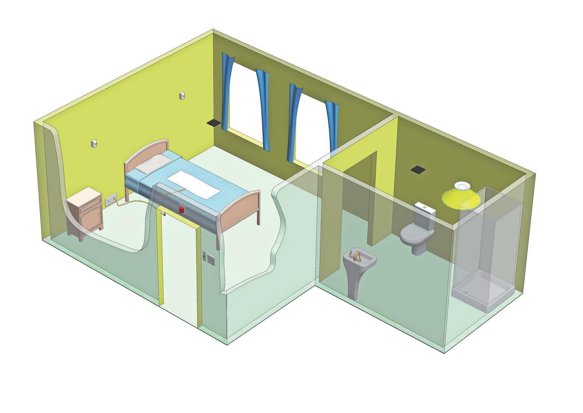
PIR Movement Sensors
Sense patient movement and instruct the controller to switch lights on, off or dim and to raise a call dependent on the status of the behaviour pattern selected.


Door Contacts
Can be set up to trigger a call when the bedroom door is opened
Benefits Of Using Quantec Dementia Care
Room Status Controller
Allows carers to arm/isolate the system and reset any active calls. Optional door bell will trigger a call when pressed by the patient
• Allows Nursing homes to offer specialist Dementia care with little additional cost
• Allows Nursing homes to meet the requirements of local authority dementia care provision targets
• Gives confidence to residents, relatives and staff of a safe, caring approach.
• Allows residents to have a greater degree of autonomy without the need for staff assistance
Overview
Incorporating a wide range of indicator panels and an extensive array of system components (including ceiling pulls, wall-mounting call points, monitoring points, water resistant alert points, overdoor lights, remote sounders, relays and call latch modules), Channel Call System is without doubt one of the most versatile and reliable conventional call systems on the market.
Channel Call System is a wired system where individual devices are connected to the main control panel which when activated, will indicate the exact location of an “event”.
Within the Channel Call System, we offer a 10 and 20 zone call controllers, which are compatible with all Channel Call System call points, ceiling pulls, infrared ceiling receivers, monitoring points, overdoor lights and remote sounders.
Depending on how the controller is configured and the devices connected to it, both standard and emergency calls can be indicated via its buzzer and zonal LEDs. Two buttons (A and B) are also provided to allow the user to reset, mute or accept standard calls.
Flush or surface call controllers are available. The N/CC800 control panels are available to cover 10-90 zones. Please contact us for bespoke systems.
Features
• Hard wired for total reliability – 4 to 6 core security cable is ideal for most installations
• Wide range of indicator panels covering 1 to 90 zones
• Extensive range of ancillaries including ceiling pulls, wall-mounting call points, monitoring points, water resistant alert points, overdoor lights, remote sounders, relays and call latch modules
• Simple to install, easy to operate and highly reliable
• All power supplies capable of 12V sealed lead acid battery charging
• Two levels of call – standard (constant tone) and emergency (intermittent tone)
• Can be used to help building managers and service providers comply with BS 8300, the Equality Act and the Care Standards Act
Features
• Nursecall
• Dementia Care
• Staff Protection
• Emergency Assistance
How Does it Work?
• Cell Call
• Affray Locations
• Care Homes
Depending on the type of calling devices used, the system can be set up to operate as a standard system – on which standard (constant tone) calls are generated – or an emergency system – on which standard (constant tone) and emergency (intermittent tone) calls are generated.
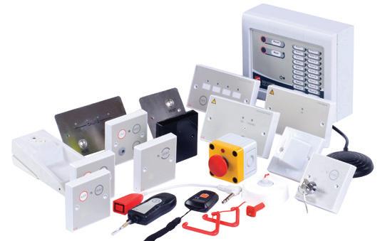
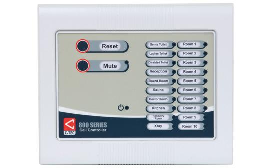
Planning a System
The following points should be considered when designing or planning a call system.
• Indicator panels
• Call Points
• Ancillary calling devices
Need Some Assistance?
• Call latch modules
• Overdoor lights
We understand that planning an installation of a nurse call system can be difficult and the rules vary, so please check with the relevant bodies before planning.
UK Rest Homes – Social Services will usually approve the installation and the standard system is normally ideal. Their main requirement is for the rest point to be within sight of the caller to ensure the call is attended to properly.
UK Nursing Homes – The local health authority will usually approve the installation and the standard system may be satisfactory but some authorities will want the emergency facility. Also, some authorities only allow button operated emergency call/reset points and others require the magnetic key type.
N/CC/941/SS 1 way Stainless steel call panel C/W PSU Optional battery back-up
N/CC/941/B Battery back-up kit for N/CC/941/SS
N/CC/944 4 way call panel – (requires N/CC/930 12V 250mA PSU)
N/CC/930 12V 250mA PSU for N/CC/944
N/CC/910/S 10 way call panel C/W PSU – Surface Mounted 214W x 178H x 37Dmm
N/CC/910/F 10 way call panel C/W PSU – Flush Mounted 214W x 178H x 37Dmm (Cut out 176 x 162 x 55Dmm)
N/CC/910/ES 10 way Expansion call panel Surface Mounted 214W x 178H x 37Dmm
N/CC/910/EF 10 way Expansion call panel Flush Mounted 214W x 178H x 37Dmm (Cut out 176 x 162 x 55Dmm)
N/CC/920/S 20 way call panel C/W PSU – Surface Mounted 214W x 178H x 37Dmm
N/CC/920/F 20 way call panel C/W PSU – Flush Mounted 214W x 178H x 37Dmm (Cut out 176 x 162 x 55Dmm)
N/CC/920/ES 20 way Expansion call panel Surface Mounted 214W x 178H x 37Dmm
N/CC/920/EF 20 way Expansion call panel Flush Mounted 214W x 178H x 37Dmm (Cut out 176 x 162 x 55Dmm)
F/PSU/12/1/BM 12V 1amp Power supply (optional for 910/920 panels)
B/12V/2.3AH/SLA 12V 2.3AH sealed lead acid battery
Call Points
N/CH/802DB Standard call point with button reset & remote socket
N/CH/804DE Emergency call/reset point (button reset)
Water Resistant Call Points
N/CH/802DEWS Slave water resistant alert point
Pull Cord
N/CH/807C Quantec ceiling pull cord unit
Remote Sounder
N/CH/888D Remote sounder
Over Door Lights
N/CH/806C Overdoor light
N/CH/806CS Overdoor light & sounder
Monitoring Points
N/CH/894DKB Button reset door monitoring point
Reset Units
N/CH/809DB Button reset point
Tail Lead
N/CH/805C/6 6ft (1.8m) tail call lead
N/CH/805/14 14ft (4.2m) tail call lead
Magnetic Reset Keys
N/CH/803M Magnetic reset key complete with keyring
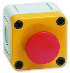
Overview
A refuge system provides a means of calling for assistance in the event of an emergency. A designated “safe area” isolates exiting occupants from the effects of smoke and heat during a fire or emergency situation. The communication system allows the person in need to inform security of their location in the building and provides an area that are relatively safe places where people who cannot easily use fire escapes.
Most risk assessments show the need for a Refuge System, giving reassurance that the building management know of the occupants whereabouts during an emergency.
The primary function of the Refuge Communication System is to provide a voice link between two points in a building. When a call is generated at the refuge area, the central control panel will sound and display the location of the incoming call.
Lifting the handset and pressing the appropriate zone button at the central station will open the speech channel (loudspeaker) allowing a ‘full duplex’ conversation to take place. The disabled refuge outstation can be used to call for assistance and reassure the person until help arrives.
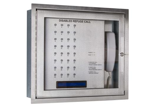
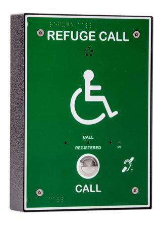

Safety Regulations & Disability Discrimination Act
Part M of the UK government’s building regulations insists that all new non-domestic buildings with more than one-storey must provide refuge areas for public safety purposes.
The Disability Discrimination Act (DDA) consists of several pieces of civil law that enable disabled people who feel they have been discriminated against to take action for damages against organisations or individuals should these considerations not be implemented to support their personal safety in the event of an emergency.
All of Channel’s disabled refuge systems are BS 9999 & BS 5839 Pt9. 2010 compliant, and we offer our consultants assistance for BS 5839, BS 9999, as well as providing relevant specification templates.
Simple and Effective – Simple and effective ‘full duplex’ two-way communication in these areas is essential, firstly to assist rescue teams in determining where assistance is required and secondly to reassure people help is on the way.
2-Way Product Features
• Battery support 24 + 3 hours (emergency)
• Fully compliant to BS 5839 Pt9
• CE 2019 certified
• Available with flush or surface mounting back box
• 2 disabled toilet alarm indicators
4, 8, 16, & 32-Way Product Features
• The Orbital refuge alarm range is a disabled refuge and disabled toilet alarm system. The main panels are offered in a stainless steel finish in either a surface or flush enclosure with black screen print and glazed lockable door.
• The master panel has the separate call switches and indicators for each disabled refuge location.
• The panel has a built in alphanumeric blue OLED screen for disabled refuge zone description and ‘32’ disabled toilet alarm zone indication.
• The disabled refuge outstations are wired in radial ‘2’ core ‘1.5’mm enhanced fire rated cable or as a loop wired ‘4’ core ‘1.5’mm enhanced fire rated cable.
• A volt free changeover contact is provided for remote call in and fault reporting. A fire panel inhibit input is also fitted as standard.
• Battery support 24 + 3 hours.
• Fully compliant to BS 5839 Pt9 and CE 2019 certified.
• A simple two core cable should be wired from the disabled toilet PSU/Sounder unit to the nearby disabled refuge outstation. The refuge outstation back box is supplied with terminals for this connection.
See page 104 for details of HARK Disabled Persons Alarm Systems (toilet alarms)
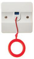
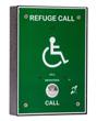
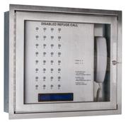
Panels
R/CH/ORB/R/RS2/F 2 Way FLUSH Stainless steel refuge panel with disabled toilet alarm indicator – Radially wired
R/CH/ORB/R/RS2/S 2 Way SURFACE Stainless steel refuge panel with disabled toilet alarm indicator – Radially wired
R/CH/ORB/R/RS4/OLED/F 4 Way FLUSH Stainless steel refuge panel with disabled toilet alarm indicator – Radially wired
R/CH/ORB/R/RS4/OLED/S 4 Way SURFACE Stainless steel refuge panel with disabled toilet alarm indicator – Radially wired
R/CH/ORB/L/RS4/OLED/F 4 Way FLUSH Stainless steel refuge panel with disabled toilet alarm indicator – Loop wired
R/CH/ORB/L/RS4/OLED/S 4 Way SURFACE Stainless steel refuge panel with disabled toilet alarm indicator – Loop wired
R/CH/ORB/R/RS8/OLED/F 8 Way FLUSH Stainless steel refuge panel with disabled toilet alarm indicator – Radially wired
R/CH/ORB/R/RS8/OLED/S 8 Way SURFACE Stainless steel refuge panel with disabled toilet alarm indicator – Radially wired
R/CH/ORB/L/RS8/OLED/F 8 Way FLUSH Stainless steel refuge panel with disabled toilet alarm indicator – Loop wired
R/CH/ORB/L/RS8/OLED/S 8 Way SURFACE Stainless steel refuge panel with disabled toilet alarm indicator – Loop wired
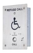
R/CH/ORB/L/RS16/OLED/F 16 Way FLUSH Stainless steel refuge panel with disabled toilet alarm indicator – Loop wired
R/CH/ORB/L/RS16/OLED/S 16 Way SURFACE Stainless steel refuge panel with disabled toilet alarm indicator – Loop wired
R/CH/ORB/L/RS32/OLED/F 32 Way FLUSH Stainless steel refuge panel with disabled toilet alarm indicator – Loop wired
R/CH/ORB/L/RS32/OLED/S 32 Way SURFACE Stainless steel refuge panel with disabled toilet alarm indicator – Loop wired
R/CH/RCO/H/GB
R/CH/RCO/H/SS/1
R/CH/RCO/S/BB/1
R/CH/RCO/F/BB/1
R/CH/RCO/S/L/BB/1
R/CH/RCO/FL/BB/1
Green outstation faceplate inc. AFILS induction loop. (requires back box)
Stainless steel outstation faceplate inc. AFILS induction loop. (requires back box)
Refuge Call Back Box – surface mounting (radial)
– C/W Disabled toilet alarm input
Refuge Call Back Box – flush mounting (radial)
– C/W Disabled toilet alarm input
Refuge Call Back Box – surface mounting (loop)
– C/W Disabled toilet alarm input
Refuge Call Back Box – flush mounting (loop)
– C/W Disabled toilet alarm input
Overview
For most people, a simple instruction like “please leave the building by the nearest available exit” can be acted upon quickly and easily. But for wheelchair users, the disabled and infirm, this isn’t always the case.
Current Building Regulations recognise this and insist that all new non-domestic buildings with more than one storey provide ‘refuge’ areas – relatively safe places where people who cannot easily use fire escapes and evacuation lifts can call for assistance and wait until help arrives.
Simple, effective two-way communication in these areas is essential, firstly to assist rescue teams in determining where assistance is required and secondly to reassure people help is on the way. Communication systems in refuge areas are known as Emergency Voice Communication (EVC) Systems. Their design and installation is governed by BS 5839 part 9.
Features
• New-look 4, 8 & 16 line master controllers with semi-recessed handsets save valuable space in crowded control rooms
• Enhanced networking facility allows up to 14 master controllers to be interlinked for systems of up to 224 lines
• New optional 224 Line Desk Controllers allow operators to communicate with up to 224 disabled refuge or fire telephone outstations from a single accessible point
• Optional anti-tamper enclosures available for controllers located in areas accessible to the public
• Wide range of ‘Disabled Refuge’ (Type B) outstations available in stainless steel or green steel (flush, surface or weatherproof options available)
• ‘Fire Telephone’ (Type A) outstations available in locking or non-locking red steel cabinets
• All outstations offer true duplex speech and can be mixed and matched to suit the application
• Unique ‘auto-learn’ facility allows fast system set up
• Devices can be named/edited using the buttons on a master controller or via an optional PC programming configurator (part no. EVC423).
• All extensions can be named with user-defined text of up to 15 characters
• Fully monitored hardware and software
• System operates at 24V DC. In the event of mains
• failure, operation can be maintained for 24 hours (standby)
• and 3 hours (in use) using 2 x 12V 7 Ahr batteries
• Optional FiTT line tester allows cable faults to be checked prior to equipment connection
• Easily interfaced to accessible toilet alarm systems, hearing loop systems, strobes or CCTV activation relays
• Ideal for disabled refuge, fire telephone and stadium marshalling applications
• Perfect for hotels, shopping malls, office blocks, transport terminals, sports stadiums, entertainment complexes, etc
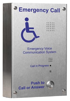
R/CH/EVC302S
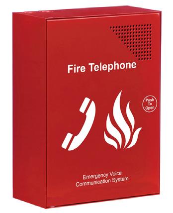
R/CH/EVC301RPO
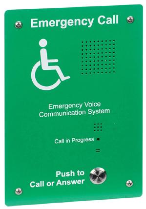
R/CH/EVC302GF
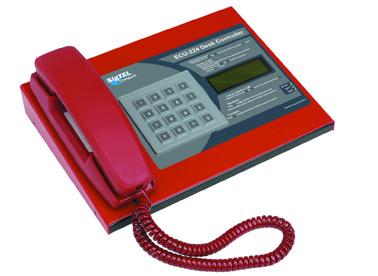
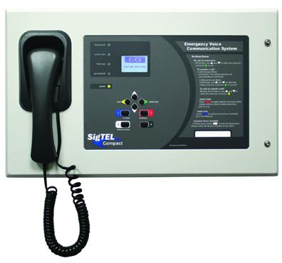
Where are disabled refuges/Type B outstations required?
An emergency voice communication system is a life safety intercom (or telephone) system designed to operate reliably in a fire alarm emergency. Its equipment and wiring must be monitored for faults that might occur prior to the emergency and its cabling and battery backup supply must ensure it keeps working during the emergency. According to BS5839 part 9, there are two types of EVC system; disabled refuge and fire telephone. They may be separate, or they may be combined into one system.
Disabled refuge systems
A disabled refuge system typically connects handsfree intercom outstations to a central control room and is used to inform management that someone needs immediate assistance to exit the building.
Fire telephone systems
A fire telephone system is used by management (and marshals at a sports ground) and the fire service before, during and after a fire to communicate with fire marshals and fire fighters.
Regulations affecting EVC systems?
The installation of an emergency voice communication system is governed by BS5839 Part 9: Code of practice for the design, installation, commissioning and maintenance of emergency voice communication systems.
Disabled Refuge Systems are called for by:
• Building Regulations; Approved Document B (Fire Safety); Volume 2, Section 4: Design for vertical escapes
• BS9999: Code of practice for fire safety in the design, management & use of buildings; Clause 41.9 Communications; Clause 46.8 Use of refuges
• Regulatory Reform Order (Fire Safety Order) Oct 2005
• Risk assessments undertaken by the responsible person must make provision for means of escape for disabled people.
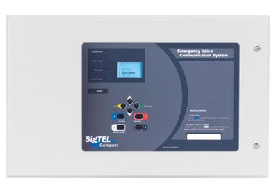
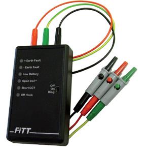
• Supplementary Guide: Means of escape for disabled people
• Equality Act 2010 (supersedes the Disability Discrimination Act)
• UN Convention on the rights of people with disabilities
Fire telephone systems are called for by:
• BS9999: Code of practice for fire safety in the design, management and use of buildings; Clause 24 Communication systems for fire and rescue service use London District Surveyors Association in conjunction with LFCDA Fire Safety Guide No. 3; Section 2: Fire Safety Measures London Fire and Civil Defence Authority (London Fire Brigade) Fire Safety Guidance Note Number: 30 (Rev 3) Guide to safety at sports grounds; 16.11: Telephone communications – internal
• Where are disabled refuges/Type B outstations required?
• Refuge areas are called for in all non-domestic buildings with more than one storey and they should be provided at each storey exit (i.e. each protected stairway affording egress)
• Examples of a refuge area include an enclosure such as a protected lobby, corridor or stairway or an area in open air such as a flat roof, balcony, podium or similar place which is sufficiently protected (or remote) from any risk of fire and has its own means of escape
Where are disabled refuges/Type B outsations regulations? Refuge areas are called for in all non-domestic buildings with more than one storey and they should be provided at each storey exit (i.e. each protected stairway affording egress).
Examples of a refuge area include an enclosure such as a protected lobby, corridor or stairway or an area in open air such as a flat roof, balcony, podium or similar place which is sufficiently protected (or remote) from any risk of fire and has its own means of escape.
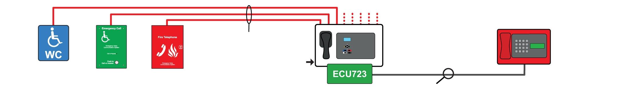
CAT5 connection lead (supplied with ECU-224)
Network SigTel system wiring with multiple ECU-224 Desk Controllers
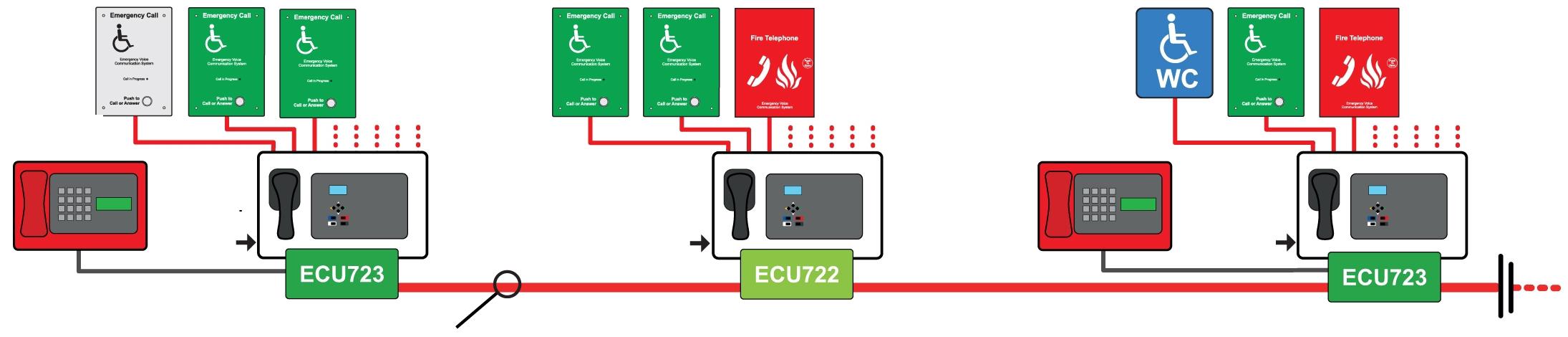
Communication Network (only required on network SigTel systems). ECU722 & ECU723 cards mount inside master controllers. Wire the network in 4 x 2 core 1.5mm2 enhanced fire rated cable. Total network length – 1km. Total no. of networked controllers = 14 (or 224 lines) ECU723 cards are only required if using an optional desk controller. If a desk controller is not required use an ECU722 card instead. Master controllers without handsets (ECU-8NT) are also available but these are not compatible with ECU-224 desk controllers.
Sigtel Refuge Alarm Systems
4-224 Way Line Controllers
R/ECU-4 4 Line SigTEL Master Controller C/W handset. Max 2 x 7Ah batteries
R/ECU-8 8 Line SigTEL Master Controller C/W handset. Max 2 x 7Ah batteries
R/ECU-16 16 Line SigTEL Master Controller C/W handset. Max 2 x 7Ah batteries
R/ECU-8NT 8 Line SigTEL Master Controller (no handset). Max 2 x 7Ah batteries
R/ECU722
Network card, allows up to 14 ECU-4, 8, 16 or 8NTs to be interlinked. (To network a controller that has an optional ECU-224 desk controller fitted use an ECU723 interface/ network card instead, see below)
R/CH/EVC385 Grey flush bezel for ECU-4, 8, 16 or 8NT controllers
R/CH/BF359/3M
Flush stainless steel anti-tamper enclosure for ECU-4, 8, 16 or 8NT Medium depth (725W x 448H x 130Dmm)
R/CH/BF359/3CL Cam lock kit for R/CH/BF359/3M or R/CH/BF359/3D
R/CH/BF359/3SL Electromagnetic solenoid lock kit for R/CH/BF359/3M or R/CH/BF359/3D
4-224 Way Line Desk Controllers
R/CH/ECU-224M
R/CH/ECU-723
Optional 1-224 line SigTEL Desk Controller with handset & display. Requires an R/CH/ ECU723 fitted with an R/CH/ECU-4, 8 or 16 Controller. R/CH/ECU-224s are NOT compatible with R/CH/ECU-8NT Controllers
R/CH/ECU-224 interface/network card. Allows an ECU-224 desk controller to be connected to an R/CH/ECU-4, 8 or 16 Controller. Can also act as a network card if networking is required. NOT compatible with R/CH/ECU-8NT Controllers
Disabled Refuge (Type B) Outstations
R/CH/EVC302GF
R/CH/EVC302GS
R/CH/EVC302F
R/CH/EVC302S
R/CH/BF359/1
Green handsfree R/CH/EVC outstation, flush mounting
Green handsfree R/CH/EVC outstation, surface mounting
Stainless steel handsfree R/CH/EVC outstation, flush mounting
Stainless steel handsfree R/CH/EVC outstation, surface mounting
IP66 rated enclosure, steel, non-locking (for R/CH/EVC302GF or F)
Disabled Refuge (Type A) Outstations
R/CH/EVC301RPO Red fire telephone outstation, C/W handset (push to open)
R/CH/EVC301RLK Red fire telephone outstation, C/W handset (key lockable)
R/CH/T-BEZ301 Red flush bezel for R/CH/EVC301RPO & R/CH/EVC301RLK
R/CH/EVC401/PH Roaming Mk2 red fire telephone handset C/W heavy duty jack plug
R/CH/EVC301/JP Single gang jack plate for use with R/CH/EVC401/PH 2
Sigtel Programming Software, Testers, Spares & Accessories
R/CH/ECU-PPT ECU handset complete with Push-to-Talk button
R/CH/FiTT/R/CH/EVC Line tester (saves time on large installations)
R/CH/CATCON Adaptor box to convert fire-rated cable to Cat 5
R/CH/XSB Blue xenon strobe, 12V (requires 1 x SDM)
R/CH/SDM Strobe driver module, 12V


A Guide to Assistance Products
Disability and the Equality Act 2010
From 1 October 2010, the Equality Act has combined all previous acts relating to discrimination, into one, more encompassing legal area.
This means that although the Disability Discrimination Act (DDA) has been superseded by the Equality Act, the Disability Equality Duty in the DDA continues to apply.
Equality Act 2010
The Equality Act 2010 aims to protect disabled people and prevent disability discrimination. It provides legal rights for disabled people in the areas of:
• Employment
• Education
• Access to goods, services and facilities including larger private cluBS and land based transport services buying and renting land or property
• Functions of public bodies, for example the issuing of licences
The Equality Act also provides rights for people not to be directly discriminated against or harassed because they have an association with a disabled person. This can apply to a carer or parent of a disabled person. In addition, people must not be directly discriminated against or harassed because they are wrongly perceived to be disabled.
The Definition of ‘Disability’
Under the Equality Act 2010, a person has a disability if:
• they have a physical or mental impairment
• the impairment has a suBS tantial and long-term adverse effect on their ability to perform normal day-to-day activities
For the purposes of the Act, these words have the following meanings:
• ‘suBS tantial’ means more than minor or trivial
• ‘long-term’ means that the effect of the impairment has lasted or is likely to last for at least twelve months (there are special rules covering recurring or fluctuating conditions)
• ‘normal day-to-day activities’ include everyday things like eating, washing, walking and going shopping
People who have had a disability in the past that meets this definition are also protected by the Act.
Progressive conditions considered a disability – There are additional provisions relating to people with progressive conditions. People with HIV, cancer or multiple sclerosis are protected by the Act from the point of diagnosis. People with some visual impairments are automatically deemed to be disabled.
Conditions that are specifically excluded – Some conditions are specifically excluded from being covered by the disability definition, such as a tendency to set fires or addictions to non–prescribed suBS tances.
System Design Guidance
Always refer to the requirements of the Building Regulations 1991, and the Building Regulations (Amendment) 1998, Part M (Access and facilities for disabled people) so as to practice good building design. All business must now provide facilities for disabled persons and this legal obligation extends to the fire alarm system.
There are numerous methods of compliance with the Disability Discrimination Act including fixed equipment such as visual alarm indicators, portable equipment such as vibrating pagers and pillows or instructing staff to ensure the safety of disabled persons using the premises.
• Failure to provide fire alarm protection for disabled persons in any business premises is a breach of the law.
• All automatic door opening installations must comply to BS 7036.
• On any door opening installation please be aware finger guards may be required either roller blind type or finger guard (plastic).
Penalties for failing to comply
The DDA gives disabled people the right to bring a civil claim against your business where they find you have breached the provisions of the DDA and discriminated against them. If in doubt contact our technical team on 0845 884 7000
Types of Disability
A typical perception of a disabled person is that they are wheelchair users, however this is a huge misconception. The split of disability according to the latest available figures in the UK is as follows:
• Hearing Impairment 51%
• Mobility Problems 22%
• Wheelchair users 3%
• Blind/partially sighted 15%
• Speech impediments 4%
• Other 5%
Who is affected by the Disability & Equality Act
• Does your organisation provide goods or services to the public?
• Do members of the general public visit your premises?
• Does your organisation conduct interviews on your premises?
• Do you carry out training/instruction in your premises?
• Does your organisation have a WEB site?
• Are you a landlord?
Useful Contacts...
Equality Advisory Support Service
Phone: 0808 800 0082
Textphone: 0808 800 0084
WeBS ite: www.equalityadvisoryservice.com
What is an Audio-Frequency Induction Loop System?
Hearing loop systems allow hearing impaired people to hear more clearly. Most hearing aids have a ‘T’ or ‘MT’ switch which allows them to pick up the electromagnetic field generated by a hearing loop system. The hearing aid converts this signal into a sound suited to its user’s specific hearing requirements.
Any person with a hearing aid positioned within or near the loop can hear the loop signal by switching their hearing aid to the correct position, allowing them to participate more effectively in general conversation, ordering goods or services, listening to public performances, etc.
A hearing loop system therefore comprises the following main elements:
• The audio source – typically a microphone, television or other audio input (sometimes more than one).
• The hearing loop amplifier
• The loop – typically one or two turns of wire usually run around the perimeter of the room or a special counter loop fixed to the underside of a table or desk.
• The receiver(s) – any hearing aid with a ‘T’ or ‘MT’ switch or a specially designed loop listening device.
In addition to the many routine benefits for hearing aid users, hearing loop systems can also be used for other limited area broadcasting applications such as museum ‘walk through’ guided tours and surveillance talkback systems.
Some hearing loop systems may require additional audio sources such as multiple microphone or line level inputs. To facilitate this, many PDA range amplifiers include a patented ‘Outreach’ socket which allows the connection of multiple inputs via a range of specially designed single gang audio connector plates.
How Does An Induction Loop System Work?
Hearing loop systems do not use radio frequencies; they operate at audio frequencies. The signal from an audio source is fed into a hearing loop amplifier, which amplifies and sets the signal level in the same way as a conventional amplifier. The amplified signal, instead of going to a loudspeaker, is fed to a closed loop of cable that is normally placed around the perimeter of the room (although other, more sophisticated ‘loop patterns’ can be employed). Using a constant current amplifier ensures the current is maintained at the set level whilst providing a flat frequency response without the need for equalisation circuitry. The current flowing through the loop generates a magnetic field that radiates in the space around the loop cable. Any lines of magnetic flux that pass through the telecoil in a receiver, such as a hearing aid, will generate a current in the coil that is then converted back to audio and fed into the listener’s ear. It is important to remember that the magnetic field will ‘bleed’ outside the perimeter of the loop and therefore a loop system cannot be considered confidential.
In normal use, hearing aids utilise a microphone that can amplify localised speech from a distance of up to 2m away. Whilst this is effective for local conversations/quiet environments, it is less effective for listening to speech or music at a distance or in front of a security screen at a ticket counter. This is because the hearing aid’s microphone also picks up any background noise in the room and unwanted speech from other conversations. A hearing loop system works by moving the required sound closer to the hearing aid via the hearing aid’s telecoil which is activated by turning it to the ‘T’ or ‘MT’ position. As telecoils are fitted as standard to most hearing aids (over 90% are said to have the ‘T’ position) hearing loop systems can be considered cost-effective compared to other hearing assistance systems. Infrared systems, for example, require special receivers, the cost and maintenance of which must be met by the service provider. Many modern hearing aids do not just amplify all frequencies equally; they are tailored to suit the user’s hearing requirements and amplify different bands by different amounts. This gives maximum intelligibility, so the user has the best chance of understanding what is said.
Which induction loop system should I use?
The Channel Safety range of hearing loop equipment comprises a huge range of amplifiers, microphones, connector plates, loop cable and test equipment covering every conceivable AFILS application. Designed to meet or exceed the requirements of BS 7594 and EN601184,our amplifiers offer excellent intelligibility, true current mode amplification,‘ phantom’ power (for use with electret microphones) and full compatibility with our Outreach plate audio input extension system. Much of our equipment is available in kit format for ease of use, specification, purchase and installation.
Please contact us for assistance in designing the system to suit your requirements.
Building Regulations
To ensure specified luminaires meet the requirements of the current building regulations it is important to consider the legislation contained within the Building Regulations. The most relevant of these are:
Approved Document B
• Approved Document B (Fire safety) – Volume 1: Dwellinghouses (2006 Edition)
• Approved Document B– Volume 2: Buildings other than dwellinghouses (2006 Edition)
Part B deals with the fire safety requirements for emergency lights and the use of thermoplastic materials.
It is our recommendation that reference be made to the latest version of the Approved Documents. Full details can be found on: www.planningportal.gov.uk
Approved Document L
• Approved Document L1A: Conservation of fuel and power (New Dwellings) (2006 Edition)
• Approved Document L1B: Conservation of fuel and power (Existing Dwellings) (2006 Edition)
• Approved Document L2A: Conservation of fuel and power (New buildings other than dwellings) (2006 Edition)
• Approved Document L2B: Conservation of fuel and power (Existing buildings other than dwellings) (2006 Edition)
Part L requires that energy efficient lighting is installed in both domestic and non-domestic dwellings, existing, new & refurbished (over 100m2).
Part L gives design information for the following (non-domestic dwellings):
• Selection of lamp types
• Effective use of daylight
• Control gear & power factor correction
• Use of lighting controls
• Luminaire efficiency
The International Protection code, commonly known as the Ingress Protection code (IP) indicates the protection afforded by an enclosure against the ingress of foreign (solid) bodies and ingress of moisture and liquids. The IP rating also classifies the protection given by an enclosure against touching live or moving parts.
The IP rating is given by the use of two numbers.
First Digit - Protection Against Ingress of Solid Objects
0 No protection
1 Protection against large sized bodies such as hands
2 Protection against medium sized bodies such as fingers
3 Protection against small sized bodies 2.5mm dia. or larger such as tools & wires
4 Protection against very small sized bodies 1mm dia. or greater
5 Protection against harmful deposits of dust (Dust proof)
Digit - Protection Against Ingress of Liquids
6 Complete protection against deposits of dust (Dust tight) 0 No protection 1 Protection against vertically falling drops of water 2 Protection against drops of water up to 15° from the vertical
against rain falling up to 60° from the vertical
against splashed water from any angle
against jets of water from any angle
against water from heavy seas
Protection against immersion for a defined period
Protection against immersion for an indefinite period
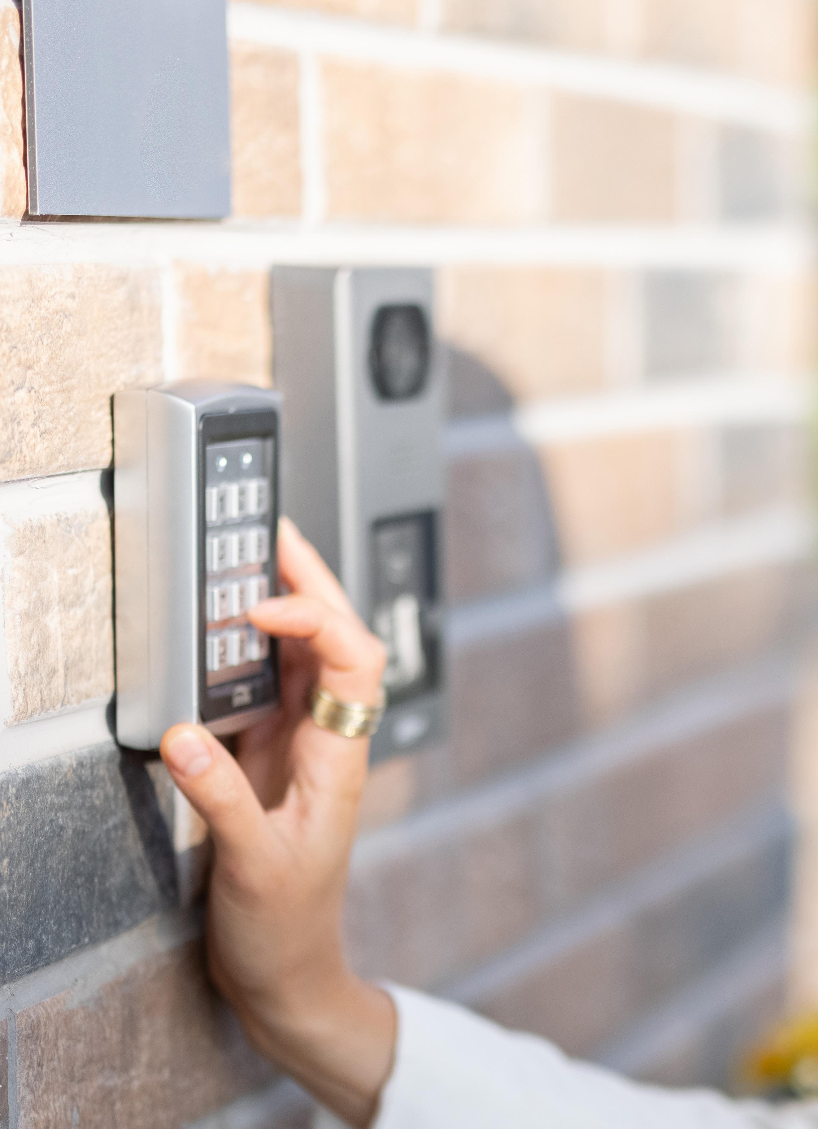

Whether you need a simple one door solution, a multi door solution for larger premises or are looking for video intercom, PIN code or a fob access enabled access system, ENTRitech™ range offers a solution.
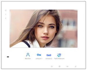
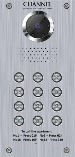
The ENTRitech 32 way video door entry system offer a simple to install user friendly stylish solution.
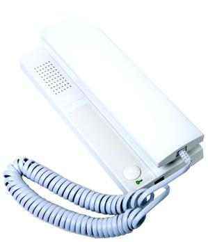
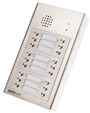
The ENTRitech audio system allows up to 18 apartments to benefit from a high quality, economic solution for their door entry requirements
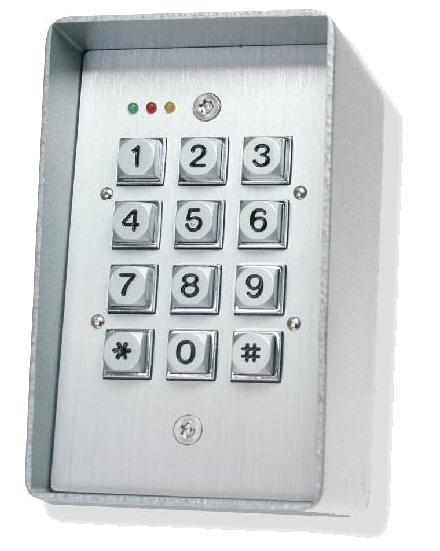
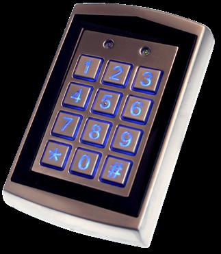
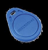

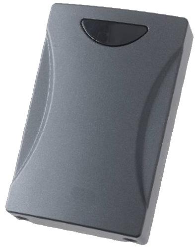
Our range of door access kits allows individual control of unlimited number of doors/gates. Whilst the kits allow easy ordering, bespoke systems can be tailored to suit host of requirements. PAGE
Overview
The latest Entritech offering from Channel combines easy use and installation with top video quality to produce a system which is installer friendly, service friendly, and householder friendly.
Features
• Simple 2 core cable installation
• Single power supply supports all monitors and outdoor stations in a flexible combination of up to 32 devices
• Clear high resolution colour picture on 7” hands free TFT monitor
• Outdoor station with built in keypad for code door unlocking 2 door release buttons so front/back doors or gates can be opened separately
• 2 outdoor door stations
• Up to 32 monitor screens
• Up to 4 monitor screens per apartment (Max. 32 monitors; i.e. 16 apartments with 2 screens, 8 apartments with 4 screens etc.)
• 2 selectable door/gate release options
• If you have 2 outdoor units the system only unlocks the appropriate door/gate
• 2core 0.75mm PVC cable
• 140m cable run (60m PSU outdoor stations – 80m PSU/last monitor)
• Simple DIP switch monitor addressing
• PIN Code entry – Up to 99 separate user codes
• Surface or flush mounted outdoor station
• Selectable door control output. Voltage free change over or 12v 300mA DC applied/removed
• Selectable ‘Lock open’ timer, 6 or 10 seconds
D/ENT/VPAN/32/PX Call Panel With Keypad & Proximity Reader. Up to 32 Screens – Two Wire Flush Mounted
D/ENT/VPAN/32 Call Panel With Keypad, up to 32 Screens. Two Wire Flush Mounted
D/ENT/VM/32 7 Inch Monitor, White. Two Wire
D/ENT/PSU/32 Central Power Supply Adapter (24v, 2.5a) One Per System
D/ENT/DIST/32 4-Channel Distributor – For use with apartments with more than one screen
D/ENT/SMB/32 Surface Mounting Box for Outdoor Call Panel
D/ENT/WH/ED White Exit Button
D/ENT/SS/EB Stainless Steel Exit Button
F/CH/EDR/FLEX Green Emergency Door Release Unit
D/ENT/AUDIO/PSU Option for Door Locks
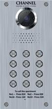

Overview
The easy-to-install 5-wire Audio only ENTRitech range has been designed for use within a wide range of applications including residential, commercial & industrial properties. ENTRitech uses up to date technology and is beautifully presented in a modern series of designs supplied in 17 gauge 1.367mm thick stainless steel. This modular system is supplied in easy to order kit form with flush kit options available from 1 way to 8 way. Please contact us for details.
Features
• Stainless steel call stations
• Cost effective in installation time and materials
• Encapsulated electronics/IP44 rated call station
• Available in flush or surface mounted versions
• 1 – 18 way systems available to special order
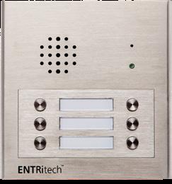
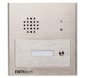
Surface Mounted Audio Kits With Embedded Intercom
D/ENT/AUDIO/1
D/ENT/AUDIO/2
D/ENT/AUDIO/3
1 way audio kit complete with stainless steel 1 button call station, 1 power supply & 1 phone
2 way audio kit complete with stainless steel 2 button call station, 1 power supply & 2 phones
3 way audio kit complete with stainless steel 3 button call station, 1 power supply & 3 phones
D/ENT/AUDIO/4 4 way audio kit complete with stainless steel 4 button call station, 1 power supply & 4 phones
D/ENT/AUDIO/6 6 way audio kit complete with stainless steel 6 button call station, 1 power supply & 6 phones
D/ENT/AUDIO/8
8 way audio kit complete with stainless steel 8 button call station, 1 power supply & 8 phones
Flush Mounted Audio Kits With Embedded Intercom
D/ENT/AUDIO/1/FL Flush 1 way audio complete with stainless steel 1 button call station, power supply & 1 phone
D/ENT/AUDIO/2/FL Flush 2 way audio complete with stainless steel 2 button call station, power supply & 2 phones
D/ENT/AUDIO/4/FL Flush 4 way audio complete with 4 button call station, power supply & 4 phones
D/ENT/AUDIO/6/FL Flush 6 way audio complete with 6 button call station, power supply & 6 phones
D/ENT/AUDIO/8/FL Flush 8 way audio complete with 8 button call station, power supply & 8 phones
Flush Mounted Audio – Call Station With Embedded Intercom
D/ENT/FL/1
D/ENT/FL/2
D/ENT/FL/3
Flush master unit with stainless steel 1 module unit complete with embedded intercom (up to 6 way)
Flush master unit with stainless steel 2 module unit complete with embedded intercom (up to 12 way)
Flush master unit with stainless steel 3 module unit complete with embedded intercom (up to 18 way)
Surface Mounted Audio – Call Station With Embedded Intercom
D/ENT/MASTER 1 1 Module stainless steel unit surface mounted complete with embedded intercom (up to 6 way)
D/ENT/MASTER 2 2 Module stainless steel unit surface mounted complete with embedded intercom (up to 12 way)
D/ENT/MASTER 3 3 Module stainless steel unit surface mounted complete with embedded intercom (up to 18 way)
Button Modules
D/ENT/AUDIO/KP Digital keypad module
D/ENT/BU01 1 Button module
D/ENT/BU02 2 Button module
D/ENT/BU03 3 Button module
D/ENT/BU04 4 Button module
D/ENT/BU06 6 Button module
D/ENT/TMB Trades men button
S/E60/A 12 Volt relay
Handset
D/ENT/AUDIO/HS Audio only handset complete with door release button
Power Supply
D/ENT/AUDIO/PSU Power Supply Unit
Overview
What to consider when choosing an Access Control System?
• How many doors/buildings do you need to secure?
• Do you need different levels of access to certain areas?
• Do you need to control who goes out as well as in? How will people exit in the event of an emergency or powercut?
• How will you allow legitimate visitors access, will you speak to them via an intercom?
• Is managing Time and Attendance important to your business?
Features
• Simple to install
• Robust construction
• IP65 Proximity reader option
• Suitable for up to 21 individual codes
• Stainless steel keypad option
Access Keypad (H)137 x (W)93 x (D)55mm
Proximity Reader (H)116 x (W)75 x (D)22mm

D/ENT/KEY/PROX/800
Proximity and Keypad Access
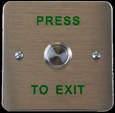
D/ENT/SS/EB
Steel Push to Exit Button
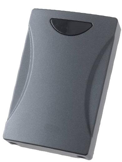
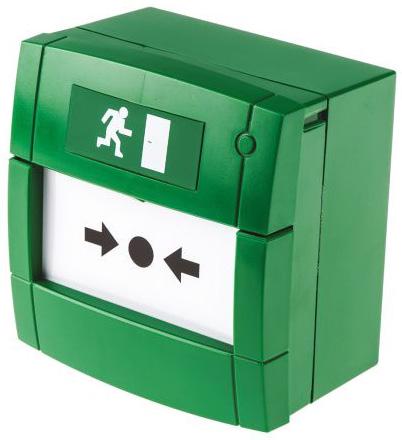
F/CH/EDR/FLEX
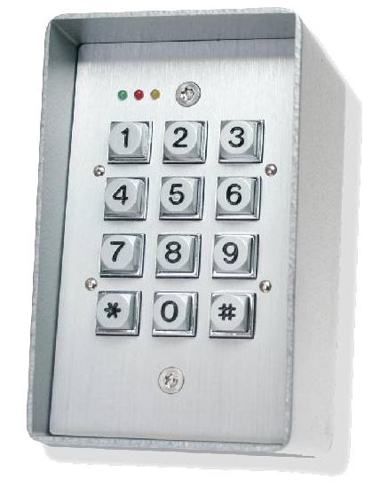
D/ENT/DA/KP/1
Steel Door Access Keypad
D/ENT/WH/ED
Break Glass – Green, No Resistor Proximity Fob/Token Blue - Single
D/ENT/STD-PCPS Proximity Card with Slot

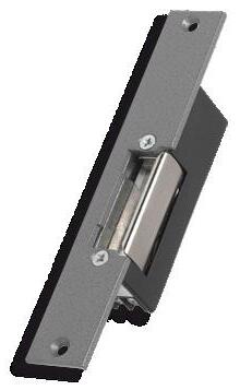
D/ENT/DA/KIT1 contains:
• 12Vdc 2Amp boxed power supply with battery back up
• Digital Keypad with up to 21 individual codes
• Exit button
• Green break-glass unit
• Electric lock release

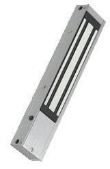
D/ENT/DA/KIT2 contains:
• 12Vdc 2Amp boxed power supply with battery back up
• Digital Keypad with up to 21 individual codes
• Exit button
• Green break-glass unit
• Magnetic lock
• Z&L bracket
Kit 4 – Proximity
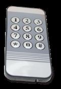
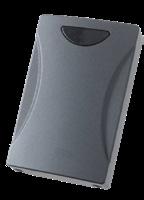
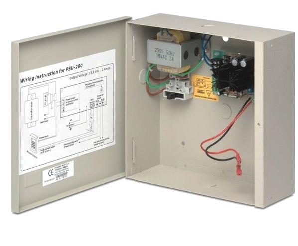

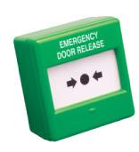
D/ENT/DA/KIT4 contains:
• 12Vdc 2Amp boxed power supply with battery back up
• Proximity reader for use with up to 2000 users
• Exit button
• Green break-glass unit
• Key fob tokens x 10 pieces
• Hand held programmer
• Magnetic lock
• Z&L bracket
Kit 5 – Keypad

D/ENT/DA/KIT5 contains:
• 12Vdc 2Amp boxed power supply with battery back up
• DG180 Keypad
• Exit button
• Green break-glass unit
• Electric Release
Kit 3 – Proximity
D/ENT/DA/KIT3 contains:
• 12Vdc 2 Amp boxed power supply with battery back up
• Proximity reader (up 2000 users)
• Exit button
• Green break glass unit
• Key fob tokens x 10 pieces
• Hand held programmer
• Electric lock release
Kit 6 – Keypad
D/ENT/DA/KIT6 Contains:
• 12Vdc 2Amp boxed power supply with battery back up
• DG180 Keypad
• Exit button
• Green break-glass unit
• Magnetic Lock
• Z&L bracket
D/ENT/DA/KIT7 contains:
• 12Vdc 2Amp boxed power supply with battery back up
• Combined keypad & proximity reader
• Exit button
• Green break-glass unit
• Key fob tokens x 10 pieces
• Electric Release
Kits
D/ENT/DA/KIT1
D/ENT/DA/KIT2
D/ENT/DA/KIT3
D/ENT/DA/KIT4
D/ENT/DA/KIT5
D/ENT/DA/KIT6
D/ENT/DA/KIT7
D/ENT/DA/KIT8
Key pad door access kit 1: including PSU, digital keypad, exit button, green break glass unit and electric lock release
Key pad door access kit 2: including PSU, digital keypad, exit button, green break glass unit, magnetic lock and Z&L bracket
Proximity reader door access kit 3: including PSU, exit button, green break glass unit, electric lock release, 10 key fobs and a hand held programmer
Proximity reader door access kit 4: including PSU, exit button, green break glass unit, magnetic lock, Z&L bracket,10 key fobs and a hand held programmer
Key pad door access kit 5: including PSU, keypad, exit button, green break glass unit, Electric release.
Key pad door access kit 6: including PSU, keypad, exit button, green break glass unit, magnetic lock and Z&L bracket
Proximity reader door access kit 7: Combined keypad & proximity reader including PSU, exit button, green break glass unit, magnetic lock and 10 key fobs
Proximity reader door access kit 8: Combined keypad & proximity reader including PSU, exit button, green break glass unit, electric release and 10 key fobs
D/ENT/DA/KIT8 Contains:
• 12Vdc 2Amp boxed power supply with battery back up
• Combined keypad & proximity reader
• Exit button
• Green break-glass unit
• Key fob tokens x 10 pieces
• Magnetic lock
• Z & L bracket
Accessories
D/ENT/DA/KP/1 Stainless steel door access keypad
D/ENT/EPX10 Standalone proximity reader
D/ENT/KEY/PROX/800 Door access keypad/Proximity Reader
D/ENT/KT10-B Blue proximity tag
D/ENT/STD-PCPS Proximity card
D/ENT/EPX10-HP Hand held programmer for use with proximity reader
D/ENT/SS/EB Stainless steel exit button
D/ENT/WH/ED White exit button
D/ENT/RIM Rim type 12V DC fail secure rim release
D/ENT/PSU 12V DC 1amp PSU
F/CH/EDR/FLEX Green emergency door release unit
D/ENT/MAG 600lbs magnetic door lock
D/ENT/MAG/MON 600lbs magnetic door lock – MONITORED
D/ENT/MAG/BRACKET Z&L Bracket for magnetic locks
D/ENT/PSU/12V/2A 12Vdc 2Amp boxed power supply
B/12V/1.2AH/SLA 12 Volt 1.2Ah sealed lead acid battery (1 block)
D/ENT/AUDIO/PSU 12V 1.5Amp dual output power supply (no battery back up)
D/ENT/PSU/12V/2A/TD PSU with time delay

Building Regulations
To ensure specified luminaires meet the requirements of the current building regulations it is important to consider the legislation contained within the Building Regulations. The most relevant of these are:
Approved Document B
• Approved Document B (Fire safety) – Volume 1: Dwellinghouses (2006 Edition)
• Approved Document B– Volume 2: Buildings other than dwellinghouses (2006 Edition)
Part B deals with the fire safety requirements for emergency lights and the use of thermoplastic materials.
It is our recommendation that reference be made to the latest version of the Approved Documents. Full details can be found on: www.planningportal.gov.uk
Approved Document L
• Approved Document L1A: Conservation of fuel and power (New Dwellings) (2006 Edition)
• Approved Document L1B: Conservation of fuel and power (Existing Dwellings) (2006 Edition)
• Approved Document L2A: Conservation of fuel and power (New buildings other than dwellings) (2006 Edition)
• Approved Document L2B: Conservation of fuel and power (Existing buildings other than dwellings) (2006 Edition)
Part L requires that energy efficient lighting is installed in both domestic and non-domestic dwellings, existing, new & refurbished (over 100m2).
Part L gives design information for the following (non-domestic dwellings):
• Selection of lamp types
• Effective use of daylight
• Control gear & power factor correction
• Use of lighting controls
• Luminaire efficiency
The International Protection code, commonly known as the Ingress Protection code (IP) indicates the protection afforded by an enclosure against the ingress of foreign (solid) bodies and ingress of moisture and liquids. The IP rating also classifies the protection given by an enclosure against touching live or moving parts.
The IP rating is given by the use of two numbers.
First Digit - Protection Against Ingress of Solid Objects Second Digit - Protection Against Ingress of Liquids
0 No protection
1 Protection against large sized bodies such as hands
2 Protection against medium sized bodies such as fingers
3 Protection against small sized bodies 2.5mm dia. or larger such as tools & wires
4 Protection against very small sized bodies 1mm dia. or greater
5 Protection against harmful deposits of dust (Dust proof)
6 Complete protection against deposits of dust (Dust tight) 0 No protection 1 Protection against vertically falling drops of water 2 Protection against drops of water up to 15° from the vertical
against rain falling up to 60° from the vertical
against splashed water from any angle
Protection against jets of water from any angle
against water from heavy seas
Protection against immersion for a defined period
Protection against immersion for an indefinite period
Product Code Page No.
F/CH/MX-5403 17
F/CH/MX-5404 17
F/CH/MX-5802 17
F/CH/MX-5803 17
F/CH/MX-5804 17
F/CH/MX-5805 17
F/CH/MX-5806 17
F/CH/MX-5807 17
F/CH/MX-5808 17
F/CH/MXP-503 17
F/CH/MXP-513M-050RD 17
F/CH/MXP-903 17
F/CH/PC 35
F/CH/PIP-001 29
F/CH/PIP-002 29
F/CH/PIP-003 29
F/CH/PIP-005 29
F/CH/PIP-006 29
F/CH/PIP-007 29
F/CH/PIP-008 29
F/CH/PIP-009 29
F/CH/PIP-012 29
F/CH/PIP-014 29
F/CH/PIP-015 29
F/CH/PIP-016 29
F/CH/PIP-059-001 29
F/CH/PIP-059-007 29
F/CH/PIP-221-035 29
F/CH/PIP-222-059 29
F/CH/PS200 21
F/CH/SMOKESABRE-01-001 41
F/CH/SOLO/100 41
F/CH/SOLO/101 41
F/CH/SOLO/108 41
F/CH/SOLO/200 41
F/CH/SOLO/330 41
F/CH/SOLO/423 41
F/CH/SOLO/424 41
F/CH/SOLO/460 41
F/CH/SOLO/461 41
F/CH/SOLO/610 41
F/CH/SOLO/811 41
F/CH/SOLO/812 41
F/CH/SOLO/814 41
F/CH/SOLO/822 41
F/CH/SOLO/823 41
F/CH/SOLO/CO 41
F/CH/SOLOA5 41
F/CH/VPS-215 29
F/CH/VPS-220 29
F/CH/VSP-005 29
F/CHAS/2 10
F/CHAS/4 10
Product Code Page No.
F/CHAS/8 10
F/CHBG/AS/COVER 10
F/CHBG/AS/COVER 18
F/CHBG/IS/95/2 18
F/CHBG/IS/DISC 20
F/CHBG/S/5 8
F/CHBG/S/5/CV 8
F/CHBG/S/AS/2 10
F/CHBG/S/SA/CV 12
F/CHBG/S/SA/WP 12
F/CHBG/WP/3 8
F/CHBG/WP/95/1 18
F/CHBGC/KIT 37
F/CHBGC/KIT/S 37
F/CHBL/6/2 8
F/CHBM/140/KIT/2 32
F/CHBM/70/KIT/2 32
F/CHBM/ADAPTER 32
F/CHBM/R/95/EXT/KIT 32
F/CHBM/SA/2 32
F/CHBM/SA/95 32
F/CHBN/95 18
F/CHBN/BASE/95 18
F/CHBN/D/RING 8
F/CHBN/RD/DB 8
F/CHBN/SU/SA 12
F/CHDR/24 34
F/CHDR/240 34
F/CHDR/95 18,34
F/CHDR/BK 34
F/CHDR/CHAIN 34
F/CHDR/PSU/2 35
F/CHDR/PSU/4 35
F/CHEV/BGU 4
F/CHEV/PB 4
F/CHEV/SYN/BGU 4
F/CHEV/SYN/BS 4
F/CHEV/SYN/GSM 4
F/CHEV/SYN/HD 4
F/CHEV/SYN/INT2 4
F/CHEV/SYN/SD 4
F/CHEV/SYN/SDWS 4
F/CHEV/SYN/SS 4
F/CHFA/SFS 36
F/CHHF/A 8
F/CHHF/A/HT 8
F/CHHF/A/HT/AS 10
F/CHHF/AS 10 F/CHHM/95 18
F/CHHM/DISC 20
F/CHHM/HT/95
Product Code Page No.
F/CHZM/IS/95 18
F/CLOOM 7
F/COVER/RD/1 18
F/COVER/WH/1 18
F/EDA-A6000 25
F/EDA-A6030 25
F/EDA-A6040 25
F/EDA-A6041 25
F/EDA-A6060 25
F/EDA-C5000 25
F/EDA-D5000 25
F/EDA-D6000 25
F/EDA-Q585 25
F/EDA-R5000 25
F/EDA-R6000 25
F/EDA-R6030 25
F/EDA-R6030 25
F/EDA-T6080 25
F/EDA-Y5000 25
F/EDA-Z5000 25
F/EDA-Z5008 25
F/EDA-Z5020 25
F/EDA-Z5100 25
F/EDA-Z6000 25
F/EDA-Z6010 25
F/EDA-Z6011 25
F/FFE-16511 39
F/FFE-16519 39
F/FFE-16521 39
F/FFE-16571 39
F/FFE-16579 39
F/FFE-16581 39
F/FFE-16589 39
F/FFE-16591 39
F/FL5000-200APO 23
F/FL5100-600APO 23
F/FL6100-600APO 23
F/FW1001/1/16 15
F/FW1001/1/32 15
F/FW1001/2/32 15
F/FW1001/HB 15
F/FW1001/NCC/16 15
F/FW1001/NCC/32 15
F/FW1001/R/16 15
F/FW1001/R/32 15
F/HCP-E/SCI 21
F/HCP-W/SCI 21
F/HCV500/0350 31
F/HCV500/0600 31
F/HCV500/0800 31
F/HCV500/1000 31
F/HCVSS/BKT 31
F/IMCP 31
F/KEY BOX 37
Product
F/KEY BOX GLASS
F/PSU/12/1/BM
F/PSU/12/2/BM
F/PSU/12/3/BM 38
F/PSU/12/5/BM 38
F/PSU/24/1/BM 38
F/PSU/24/2/BM 38
F/PSU/24/3/BM 38
F/PSU/24/5/BM 38
F/PSU24/1.5/BMEN54 32
F/PSU24/1.5/BMEN54 38
F/PSU24/3/EN54/1 38
F/RW1000-400APO 27
F/RW1000-600APO 27
F/RW1000-700APO 27
F/RW1300-010 27
F/RW1300-020 27
F/RW1300-110APO 27
F/RW1300-210APO 27
F/RW1300-211APO 27
F/RW1500-110APO 27
F/RW1500-120APO 27
F/RW1500-210APO 27
F/RW1500-220APO 27
F/RW1500-800APO 27
F/RW1700-030APO 27
F/RW1700-051APO 27
F/RW1700-052APO 27
F/RW1800-060APO 27
F/RW1900-901APO 27
F/SA5000-200APO 22
F/SA5000-400APO 22
F/SA5000-600APO 22
F/SA5000-700APO 22
F/SA5100-400APO 22
F/SA5100-600APO 22
F/SA5100-700APO 22
F/SA5100-810APO 22
F/SI/CAP2WHT 21
F/SR/MOUNTING 21
F/SVL/MULTI/2-6 31
F/SVL/ZC 31
F/SVM/24V-5A/BASIC 31
F/SVM/24V-8A/BASIC 31
F/TCH-B200 21
F/VAD/C/1 9
F/VAD/C/3 9
F/VAD/W/1 9
F/VAD/W/3 9
F/VAD/WB/C/2 9
F/VAD/WB/C/4 9
F/VAD/WB/W/2 9
F/VAD/WB/W/4 9
F/VEA-040-A00 28
F/VEA-040-A10 29
F/VEP-A00-P 29
F/VEP-A10-P 29
F/VES-A00-P 29
F/VEU-A00 29
F/VEU-A10 29
F/WSK/321/0005/61 31
F/YBN/R/3 WHT 21
F/YBN/R/3/SCI 21
F/YBO-BS B2WHTRL 21
F/YBO-BS WHT 21
F/YBO-R/3 RED 21
F/YBO-R/3/WHT 21
F/YBO-R/SCI RED 21
F/YBO-R/SCIWHT 21
S/BATT/EDA-Q690 25
S/BG/COVER/SA 12
S/BG/TESTKEY/1 8
S/BG/TESTKEY/AS 10, 18
S/BG/TESTKEY/SA 12
S/CH/BF376 33
S/E15/A 33
S/E20/A 10
S/E55/A 33
S/E60/A 33
SP/CHBM/140/KIT 32
SP/CHBM/70KIT 32
SP/CHSM/P/AS 10
Product Code Page No.
E/BEZ/SOL 59
E/BHDA/1 83
E/BHDA/1/ID 85
E/BHDA/2 83
E/BHDA/2/ID 85
E/BK/M3/LED/3/LI 58
E/BK/M3/LED/3/ST/LI 58
E/CH/ELTS 86
E/CHFO/FMB/BR 67
E/CHFO/FMB/SI 67
E/CHFO/FMB/WH 67
E/CHFO/M3/L/BRST 67
E/CHFO/M3/L/CHST 67
E/CHFO/M3/L/SAST 67
E/CHFO/M3/L/WHST 67
E/CHFO/WMB/BR 67
E/CHFO/WMB/SI 67
E/CHFO/WMB/WH 67
E/CHVL/M3/L/BRST 68
E/CHVL/M3/L/CHST 68
E/CHVL/M3/L/WHST 68
E/DA/M3/LED/3/ST 68
E/DLDA/1/** 83
E/DLDA/1/**/ID 85
E/DLDA/2/** 83
E/DLDA/2/**/ID 85
E/DLDA/3/** 83
E/DLDA/3/**/ID 85
E/EM/RC 55, 57, 58, 62, 74, 75, 88, 89
E/EX/M3/LI 64
E/EXDA/1** 83
E/EXDA/1**/ID 85
E/EXDA/2** 83
E/EXDA/2**/ID 85
E/EXDA/3** 83
E/EXDA/3**/ID 85
E/EXDA/4 83
E/EXDA/4/ID 85
E/GL/LED/M3/5W/WH/LI 77
E/GL/LED/NM3/1W/ WH/LI 76
E/GLEN/3W 78
E/GLEN/BEZ/BK 78
E/GLEN/BEZ/SI 78
E/GR/M3/ULTRA/LI 71
E/GR/NM3/IP65/RC/LI 70
E/GR/NM3/LED/IP65/ ST/LI 70
E/GR/NM3/LED/LI 70
E/GU32/IP65/ST/LI 72
E/GU32/LI 73
E/ID/MESH/HUB/ID 85
E/ID/MESH/NODE/ID 85
E/ID/MESH/WORKS/ID 85
Product Code Page No.
E/ME/LED/SRK/1 56
E/ME/M3/LED/IP65/LI 56
E/ME/M3/LED/IP65/ST/LI 56
E/MILAN 88
E/MILAN/BEZ/BK 88
E/MILAN/BEZ/BR 88
E/MILAN/BEZ/CH 88
E/MILAN/EYE/BK 88
E/MILAN/EYE/WH 88
E/MILAN/M3/MW/RC/LI 88
E/MILAN/M3/RC/LI 88
E/MM/BLADE 57
E/MM/M3/LED/LI 57
E/PIC/AL/AD 62
E/PIC/AL/AL 62
E/PIC/AL/AR 62
E/PIC/AL/AU 62
E/PIC/ME/LED/BLADE 56
E/PIC/ME/LED/PACK 56, 57, 58
E/PIC/RZ/PACK 65
E/RZ/M3/LED/F/LI 65
E/RZ/M3/LED/H/LI 65
E/RZ/M3/LED/R/LI 65
E/RZ/M3/LED/W/LI 65
E/SOHO 89
E/SOHO/M3/DA/ID 85
E/SOHO/M3/DALI 83
E/SOHO/M3/MW/RC/LI 89
E/SOHO/M3/RC/LI 89
E/SOHO/MW 89
E/SOLENT/M3/LI 59
E/STRATOS/110 60
E/STRATOS/230 60
E/STRATOS/24 60
E/STRATOS/50 60
E/STRATOS/COLD 60
E/STRATOS/HI 60
E/STRATOS/M3 60
E/STRATOS/M3/2W 60
E/STRATOS/PIC/KIT 60
E/STRATOS/REC/KIT 60
E/STRATOS/ULTRA 61
E/TSDA/1 83
E/TSDA/1/ID 85
S/AZ/BK/COV 81
S/LEG/DA/AD/3 68
S/LEG/DA/AL/3 68
S/LEG/DA/AR/3 68
S/LEG/DA/AU/3 68
S/LEG/FO/AD 67
S/LEG/FO/ALR 67
S/LEG/FO/AU 67
S/LEG/VL/AD 68
S/LEG/VL/ALR 68
S/LEG/VL/AU 68
SP/BX/AD/DG/EN 69
Product Code Page No.
SP/BX/AL/DG/EN 69
SP/BX/AR/DG/EN 69
SP/BX/AU/DG/EN 69
SP/SOHO/M3/MW/ST 89
SP/SOHO/M3/ST 89
Product Code Page No.
N/CC/941/B 111
N/CC/941/SS 111
N/CC/944 111
N/CH/802DB 111
N/CH/802DEWS 111
N/CH/803M 107, 111
N/CH/804DE 111
N/CH/805/14 107, 111
N/CH/805C/6 107, 111
N/CH/806C 111
N/CH/806CS 111
N/CH/807C 111
N/CH/809DB 111
N/CH/888D 111
N/CH/894DKB 111
N/CH385 107
N/CHWB/BN/12V/DB 105
N/HARK/1 105
N/HARK/1/PB 105
N/HARK/1/PC 105
N/HARK/1/PSU 105
N/HARK/1/RS 105
N/HARK/CA 105
N/HARK/RI/1 105
N/HARK/RI/1/SS 105
N/HARK/RI/2 105
N/HARK/RI/2/SS 105
N/HARK/RI/3 105
N/HARK/RI/3/SS 105
N/HARK/RI/4 105
N/HARK/RI/4/SS 105
N/HARK/RI/5 105
N/HARK/RI/5/SS 105
N/HARK/RI/6 105
N/HARK/RI/6/SS 105
N/HARK/RI/7 105
N/HARK/RI/7/SS 105
N/HARK/RI/8 105
N/HARK/RI/8/SS 105
N/HARK/RI/9 105
N/HARK/RI/9/SS 105
N/HARK+ 105
N/HARK+/PB/SS 105
N/HARK+/PC/SS 105
N/HARK+/PSU/SS 105
N/HARK+/RS/SS 105
N/QT1001/S 107
N/QT302RX 107
N/QT302RXRS 108
N/QT412RXA 107, 108
N/QT423 107, 108
N/QT601-2 107
N/QT601-2 108
N/QT602 107
N/QT602M 107
N/QT602R 107
N/QT603 107, 108
N/QT604 107
Product Code Page No.
N/QT606 107, 108
N/QT606A 107, 108 N/QT607 107
N/QT608C 107, 108 N/QT608CD 107, 108
N/QT609 107
N/QT609RS 107
N/QT611 107, 108
N/QT630 108
N/QT633 108
N/QT636 108
N/QT638 108
N/QT688/2 107
R/CH/BF359/1 116
R/CH/BF359/3CL 116
R/CH/BF359/3M 116
R/CH/BF359/3SL 116
R/CH/CATCON 116
R/CH/ECU-224M 116
R/CH/ECU-723 116
R/CH/ECU-PPT 116
R/CH/EVC301/JP 116
R/CH/EVC301RLK 116
R/CH/EVC301RPO 116
R/CH/EVC302F 116
R/CH/EVC302GF 116
R/CH/EVC302GS 116
R/CH/EVC302S 116
R/CH/EVC385 116
R/CH/EVC401/PH 116
R/CH/FiTT/R/CH/EVC 116
R/CH/ORB/L/RS16/ OLED/F 113
R/CH/ORB/L/RS16/ OLED/S 113
R/CH/ORB/L/RS32/ OLED/F 113
R/CH/ORB/L/RS32/ OLED/S 113
R/CH/ORB/L/RS4/ OLED/F 113
R/CH/ORB/L/RS4/ OLED/S 113
R/CH/ORB/L/RS8/ OLED/F 113
R/CH/ORB/L/RS8/ OLED/S 113
R/CH/ORB/R/RS2/F 113
R/CH/ORB/R/RS2/S 113
R/CH/ORB/R/RS4/ OLED/F 113
R/CH/ORB/R/RS4/ OLED/S 113
R/CH/ORB/R/RS8/ OLED/F 113
R/CH/ORB/R/RS8/ OLED/S 113
R/CH/RCO/F/BB/1 113
R/CH/RCO/FL/BB/1 113
R/CH/RCO/H/SS/1 113
R/CH/RCO/S/BB/1 113
R/CH/RCO/S/L/BB/1 113
R/CH/SDM 116
R/CH/T-BEZ301 116
R/CH/XSB 116
R/ECU-16 116
R/ECU-4 116
R/ECU-8 116
R/ECU-8NT 116
R/ECU722 116
R/CH/RCO/H/GB 113 Product Code Page No.
At Channel, we are dedicated to being your trusted safety partner.
As industry experts with over 45 years of safety expertise, we have built a loyal customer base driven by an excellence in technical and customer support. We continue to offer our renowned end-to-end design service and new CPD training for professionals looking to develop their knowledge of fire safety and emergency lighting solutions.
Free CPD training
Free design service
Free site visits
Breadth & depth of product range
Competitive pricing
Extensive product ranges
Trusted for over 45 years
International Committee for Emergency Lighting (ICEL), Lighting Industry Association (LIA), Electrical Distributors Association – affiliate member (EDA) & Apollo Partner Plus


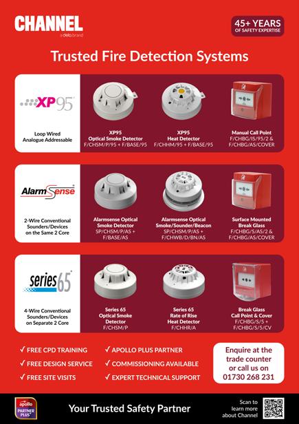
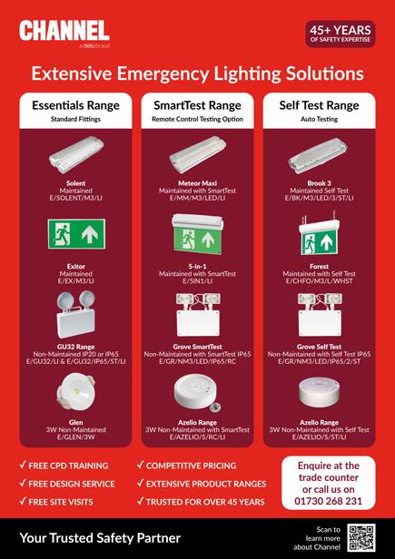

Come and join us for a CPD training day. Our industry experts will help you expand your fire safety and emergency lighting knowledge.
BS5839 PT1 2017 Fire Detection and Fire Alarm Systems
BS5266 PT1 2016 Understanding Emergency Lighting Design & Installation

BS5266pt12016 – UnderstandingEmergency LightingDesign&InstallationRequirements TrainingCourse
Apollo Fire Detectors Ltd is one of the largest independent smoke detector manufacturers in the World. Apollo offers solutions for Analogue Addressable, 2-wire conventional, 4-wire conventional and wireless fire detection devices and alarm systems. Channel’s relationship with Apollo has positioned it as a leading systems designer and supplier.


Fike Safety Technology Ltd is a globally recognised supplier of products that protect people, critical assets and facilities from hazards such as fire. Fike offers solutions for 2-wire conventional systems.
Cranford Controls Ltd specialise in the manufacture of audible and visual warning devices along with sounders, beacons and ancillary devices for the fire, security and process control industries.
The Solo range is available in economical and convenient kit forms as well as the added bonus of a range of Detector testing aerosols.

Advanced systems are found in applications from small, single-panel fire panel sites to huge multi-node networks, in many prestigious and challenging locations.
Hochiki is one of the Worlds’ leading manufacturers of quality fire detectors and alarms for commercial and industrial applications. Hochiki’s wide range consists of Sensors, Bases, Audio & Visual, Modules, Manual Call Point and Beam Detection.


VESDA by Xtralis very early warning aspirating smoke detection solutions with continuous air sampling provide the earliest possible warning of an impending fire hazard. VESDA aspirating smoke detectors buy the critical time needed to investigate an alarm and initiate an appropriate response to prevent injury, property damage or business disruption.
C-TEC is a leading UK independent manufacturer of quality life safety electronic equipment with a portfolio of products that includes Fire Alarm control panels, Voice Alarm systems, Power Supplies, Nurse Call systems and Audio-Frequency Induction Loop systems.
With over 65 years of electrical industry experience, Deta has grown to become a trusted market leading manufacturer and distributor of wiring, lighting, cable management and electrical installation accessories, with a reputation for unrivalled quality, reliability, service and value for money. As the number one electrical brand of choice amongst new build housing developers, Deta’s products are widely specified and installed across the private and social housing sectors, as well as high rise developments, student accommodation and care homes.
Steeped in over 25 years of history, Deta Electrical’s long established Vimark brand holds a reputation for the supply of high quality, value for money electrical and wiring accessories. Offering a wide portfolio of products, including wiring accessories, motion sensors, ventilation, hand dryers, back boxes and electrospares, Vimark is a long established and trusted brand that supports electrical contractors with their everyday installation requirements.
TTE is a market leading brand of electrical conduit tube and fittings, combining the former Top Tubes Electrical and Stephen Glover businesses. With more than 50 years’ experience, TTE has been specified and installed on many high-profile projects, including the London 2012 Olympic site, Wembley Stadium, Westfield Shopping Centre, Dubai International Airport and The Louvre Museum Abu Dhabi. TTE offers a reliable and best in class cable management solution that is fully compliant with British Standards.
A long established brand, well regarded for its vast range of high quality installation materials, the trusted Tower brand represents an exciting addition to Deta’s comprehensive brand portfolio. The Tower offer includes its highly acclaimed range of Installation Materials, including the original Tower Cable Clips, an 18th Edition Fire Rated range, Portable Power and Low Voltage Cable.
Established in 1978, Brackenheath is renowned for supplying high quality and competitively priced domestic and commercial lighting products. Through continuous investment in LED and sensing technologies, Brackenheath pioneered the design of its market leading iSpot® range of slim profile, driverless LED Floodlights and continues to lead the way in bringing to market new and innovative LED lighting solutions.
Since its inception in 1908, Briticent Site Electrics has enjoyed more than 100 years of successful trading with a long-standing customer base. Briticent built its reputation on the Gripper® range of handlamps, and over the years has developed a core range of essential site lighting and power distribution products. Briticent continues to lead the way with new and innovative energy saving products, becoming the site lighting brand of choice amongst electrical installers throughout the UK and Ireland.
Deta.e offers products that seamlessly combine Deta Electrical’s core value of environmental preservation with its long established and trusted reputation for delivering high quality electrical products at competitive prices. Offering a range of smart, safe, and secure EV charge points, Deta.e embraces cutting edge technologies that offer sustainable solutions to assist homeowners and businesses in making an easy transition to a new energy efficient future. (deta-e.co.uk)
A trusted UK industry leader synonymous with quality and innovation, Timeguard has more than 25 years’ experience in the manufacture and sale of time, light, safety, wi-fi and climate control electrical products. Continuously delivering energy savings that owners and occupiers are looking for, alongside the creation of new designs that offer easy installation, Timeguard has become a favourite among homeowners and installers. (timeguard.com)