P-A7P038PP - Issue 1
www.parker.com
AZ-Cylinder - Conforming to ISO 15552
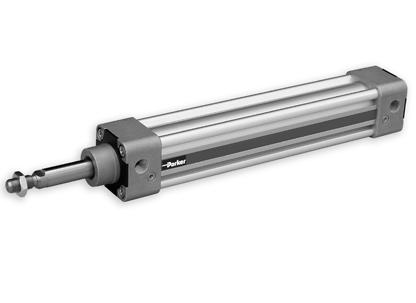
AZ-Zylinder - konform zu ISO 15552
See ISO 4414-1982 for safety requirements covering the installation and use of pneumatic equipment.

Débrancher les connexions pneumatiques et électriques avant réparation ou maintenance.
Voir ISO 4414-1982 pour les règles de sécurité des installations et utilisation des équipements pneumatiques.
Vor Reparatur- oder Wartungsarbeiten sind alle pneumatischen und elektrischen Versorgungsleitungen von der Pneumatikkomponente zu trennen.
Siehe ISO 4414-1982 bzw. DIN 24 558 bezüglich den Sicherheitsvorschriften für Installation und Einsatz von Pneumatikkomponenten.
Prelubricated, further lubrication is not normally necessary. If additional lubrication is introduced it must be continued. The following oils are recommended.
Pré-lubrifé, une lubrifcation ultérieure n’est pas nécessaire. Si une lubrifcation additionnelle est effectuée, elle doit obligatoirement être renouvelée périodiquement. Les huiles suivantes sont recommandées.
Vorgefettet. Geeignet für den Betrieb mit ungeölter Druckluft.
Nach Betrieb mit geölter Druckluft müssen Zylinder weiterhin mit geölter Luft betrieben werden. Folgenden Ölsorten werden empfohlen.
Prelubrifcato, non necessita di ulteriore lubrifcazione. Nel caso di lubrifcazione aggiuntiva, questa dovrà essere continua. Sono raccomandati i seguenti lubrifcanti.
Lubricado de fábrica. No necesita lubricación. Si se lubrica, es necesario seguir haciéndolo. Se recomiendan los siguientes aceites.
Initialsmord, behöver normalt inte tillsatssmörjas.
Prima di effettuare interventi di manutenzione verifcare che sia l’alimentazione elettrica che quella pneumatica siano disattivate. Attenersi alla nomativa ISO 4414-1982 che regola l‘installazione e l‘uso di componenti pneumatici.
Desconectar las conexiones neumáticas y eléctricas antes de efectuar cualquier reparación o mantenimiento. Ver ISO 4414-1982 para reglas de seguridad de las instálaciones y utilización de equipos neumaticós.
Koppla ifrån luft och elektriska anslutningar innan reparationsoch underhållsarbeten påbörjas. Se ISO 4414-1982 för säkerhetsbestämmelser täckande installation och användning av pneumatisk utrustning.
Påbörjad tillsatssmörjning måste dock fortsätta. Följande oljor rekommenderas.
AZ Matrix for Material Code AZ Matrix Materialcode Type Typ Series Serie Version Ausführung Diameter Durchmesser Stroke Hub Extended rod Kolbenstangen- verlängerung Air Connection Luftanschluß Seals Dichtungen Grease Fett Rod material Material Kolbenstange Thread on piston rod Kolbenstangengewinde Mounting on rod Kolbenstangen Befesigung Cylinder Mounting Zylinderbefestigung Accesoiries Zubehör Label Typenschild A1 AZ Standard 1 with cushioning without magnet K Ø32x x x x x A Standard A Standard (NBR) A Standard A Steel, high-alloyed (standard) 0 none 0 none 0 none 0 none A Serie A2 AZD With through piston rod 2 without cushioning without magnet L Ø40 B Tube rotated 90° B high tempera- ture B Smooth running grease B Steel, high-alloyed (V2A) A Standard (external thr ead) A Standard with piston rod eye A Mounting A Position Y with locking unit B Special A 3 AZZ Standard with tie rod 5 with cushioning with magnet M Ø50 C Tube rotated 180° C NBR with metal scraper B External thread (special) B Standard with piston rod clevis B Mounting A Position C Special A4 AZZD With tie rod and through piston rod 6 without cushioning with magnet N Ø63 D Tube rotated 270° D Hydr. (10bar) with metal scraper C Internal thread C Standard with compensation coupling C Mounting A Position D Special P Ø80 E Single end porting front D Standard with coupling D Mounting A Position E Special Q Ø100 F Single end porting rear E Special thread with piston rod eye E Mounting BA Position F Special G GHead cover rotated 90 degrees F Special thread with piston rod clevis F Mounting BA Position G Special H HHead cover rotated 180 degrees G Special thread with compensation coupling G Mounting B Position K K Head cover rotated 270 degrees H Special thread with coupling H Mounting B Position K Mounting BAS Position L Mounting BAS Position M Mounting C Position N Mounting C Position P Mounting D Position R Mounting D Position S Mounting EN Position T Mounting EN Position U Mounting EN locked Position W Mounting EN locked Position
Ref No. Insert item part number prior to installation Inscrire la référence dde l‘appareil avant installation Vor Einbau Bestellnummer eintragen. Inserire il codice prima dell‘installazione Rellenar referencia antes del montaje Fyll artikelnummerföre installationen P(e)max = 1MPa (10bar) Standard temp T = -20°C + 80 °C High temp T = +150°C
Disconnect air and electrical supplies before attempting repair or maintenance.
Oil Company Designation Grade Century Oils P.W.L.A. 32 Alexander Duckham Zurcon 4 32 Gulf Harmony 43AW32 Shell (UK) Oil Tellus 37 32 Burmah Castrol Hyspin AWS3232 Edgar Vaughan Hydordrive HP10032 Esso Petroleum NUTOH32 32 BP HLP 32 32 Mobile Oil Company DTE Oil - Lite 32 Mobile VPI-A 32 Silkolene Derwent 32 32
Abmessungen - Grundzylinder, Baureihe AZ…., Ø 32 – 100 mm
Dimensions – Basic Cylinder with Through Piston Rod, Series AZD...., Ø 32 – 100 mm
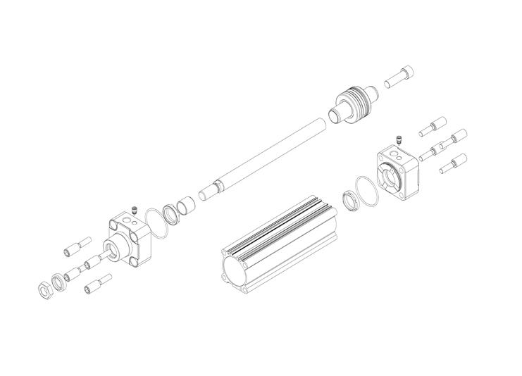
Abmessungen – Grundzylinder mit durchgehender Kolbenstange, Baureihe AZD...., Ø 32 – 100 mm
Table (mm) – Series AZ...., AZD...., AZZ...., FSE
(mm) – Baureihe AZ...., AZD...., AZZ..., FSE
+Stroke" l12RAMØBAd11BGEE
Dimensions – Multiple Position Cylinder, Series AZZ...., Ø 32 – 100 mm
Abmessungen – Mehrstellungszylinder, Baureihe AZZ...., Ø 32 – 100 mm
Dimensions - Cylinder with Locking Unit FSE..., Ø 32 – 100 mm
Einbaumaße – Zylinder mit Feststelleinheit FSE..., Ø 32 – 100 mm
Seal Kit: Dichtsatz: T2 T1 / T3 T1 / T3 ◊ ◊ ◊ ◊
Dimension
Maßtabelle
Cyl.ØØBd11Ød2EF3Gl2"l8
323012 474,530,52094632,5223016G1/8 403516 555,33420,51056,538243516G1/4 504020 658,53128106846,5324016G1/4 634520 7883326121856,5324516G3/8 804525 95935,532,51281072404517G3/8 1005525 115133737,51381089405517G1/2 Cyl.ØØLKKK
VA VDWHWMH1L4
Stroke L11 + Stroke 3246M10x1,2520M610174 5261294142183 4054M12x1,2514,5M613194 4,53012102,5160205 5066M16x1,516M817244 63715119,5176231 6380M16x1,516M817244 63714138203246 80102M20x1,520,5M1022304 64618152218292 100126M20x1,519M1022304 65118193,5230307 Seal Kit Order Codes Bestellnummern Dichtsätze: Cyl.ØStandard Viton 32 KL7222KL7223 40 KL7224KL7225 50 KL7226KL7227 63 KL7228KL7229 80 KL7230KL7231 100 KL7232KL7233
PL RT SWSW1
+
L4+ Stroke L11+ Stroke H1 ISO-Cylinder ISO-Zylinder Cyl Ø T1 T2 T3 3210 - 12 Nm65 - 6 Nm54 - 5 Nm6 4010 - 12 Nm612 - 14 Nm64 - 5 Nm6 5016 - 20 Nm816 - 18 Nm109 - 10 Nm8 6316 - 20 Nm816 - 18 Nm109 - 10 Nm8 8026 - 32 Nm1020 - 23 Nm1218 - 20 Nm10 10026 - 32 Nm1020 - 23 Nm1218 - 20 Nm10 T3 = torque tie rod cylinder / Anzugsdrehmoment Zugstangenzylinder = across fats tie rod cylinder / Schlüsselweite Zugstangenzylinder = Grease : Standard 4 gr. KL8220 / Fett Standard 4 gr. KL8220 = Locking fuid: Loctite 638 / Klebstoff: Loctite 638 ◊ = Included in seal kit / Dichtsatz enthalten Dimensions for Basic Cylinder,
AZ....,
– 100 mm Adjusting screw SW 4 mm (for cushioning) SW 2,5 for Ø 32-50 mm SW 4 for Ø 63-100 mm l +Stroke +Stroke WH+Stroke l +Stroke l +Stroke
Series
Ø 32
