Installation / Operating & Maintenance Instructions For H Series Needle, O.S.& Y., Hi-Pro Ball Valves & Flange Manifolds.
Note: These instructions apply to valves installed in manifolds, needle valves, Pro-Blocs and Mono-Flanges. Operating, Installation, Maintenance Instructions and Safe Practices REF 7/03.
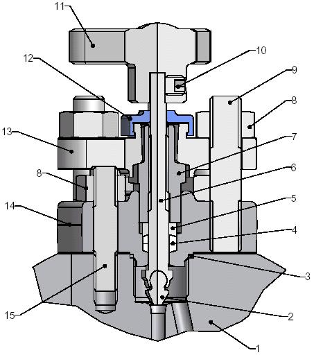
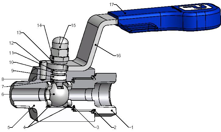
Refer to page 3 for relevant drawings
Operating.
H series manifolds & needle valve: To close, rotate handle (8) in clockwise direction until stop is felt up to a maximum torque of 6 Nm.
To open, fully rotate the handle (8) in a counter clockwise direction until backstop is located, the valve will be in its fully opened flow condition after approximately 3 turns of the handle.
H series outside screw and yoke: To close, rotate handle (11) in clockwise direction until stop is felt up to a maximum torque of 6 Nm
To open, fully rotate the handle (11) in a counter clockwise direction until backstop is located, the valve will be in its fully opened flow condition after approximately 3 turns of the handle (11).
Hi-Pro ball valves: To close operate handle (17) until it is at 90 degrees from the valve body. To open, move handle 90 degrees so that handle is in line with body and reaches the stop pin position. (12) This valve has a limited operating movement of 90 degrees, further movement being prevented by a mechanical stop pin. Ball valves should always be fully opened or fully closed and not left in any mid position.
Installation Instructions
H series manifolds & needle valve: Needle valves supplied with weld connections will generally be supplied, unless specified and/or agreed with customer, fully assembled. Prior to welding Parker Hannifin ltd recommend removing the head assembly from the body.
The valve body should be welded into the system following the appropriate welding procedure. To prevent ingress into the valve body the well thread for the valve head unit should be fully protected. After welding the valve head unit should be assembled into the valve body: -
A. Ensure the spindle is fully retracted by holding valve head unit and turning handle (8) counter clockwise until stop is felt.
B. Place stainless steel washer (3) into body recess at the top of the M16 body thread. Apply suitable lubricant to stainless steel thread (12) prior to assembling valve head to body
C. Tighten bonnet hexagon (12) into valve body (1) to 108 Nm (6000 psi/414 bar) Standard Head Assembly *
(1) To 122 Nm (10000 psi /689 bar) High Pressure Head Assembly – Designated HP *

* Note – Mono-Flange uses standard head assembly and Pro-Bloc uses high pressure head assembly.
D. Place rolled locking pin (13) into the nearest one of the two 3mm holes to the bonnet hexagon and insert until fully located.
E. The valve gland will be fully adjusted at the factory but should adjustment be required see Maintenance section. Any style of valves supplied with threaded or compression ends should be installed into pipe work using standard practices associated with the type of thread specified together in the case of taper threads with an appropriate thread sealant recommended by the owner. Valves provided with A-LOK or CPI ends will have assembly instructions included with the valve in the packing box.
Hi-Pro Ball valves: Care should be taken to ensure that the end connector (1) is firmly held by an appropriate spanner / wrench (size varies depending on size of valve) to prevent any movement when assembling or disassembling pipe or tube connection.
Flanged Manifolds: The flanges should be assembled using standard industry recognized practices such as ASME B31.3
Page 1 of 3
Maintenance Instructions

H series manifolds & needle valve: Gland adjustment becomes necessary when the valve is visibly leaking through the spindle just below the operating handle, or prior to operation when no torque or resistance is evident when operating the valve handle (8). Adjustment to the gland can be carried out to prevent leakage.
CAUTION (Dual seal heads: The primary seal on this valve is an o-ring. If gland adjustment is being carried out, then the primary seal is failing. At this point we would recommend replacing the complete valve cartridge.
SAFETY NOTE adjustment should be carried out at zero pressure, as follows:-
A. Fully close the valve by turning the handle (8) in a clockwise direction to stop lightly on seat (max. 2 Nm).
B. Open the valve 1 full turn by rotating the handle (8) in a counter clockwise direction.
C. Loosen gland lock nut (11)
D. Tighten gland nut (7) to 11 Nm for PTFE packing and 11 Nm for Grafoil.
E. Re-tighten gland lock nut (11) to 25 Nm
F.
Hi-Pro Ball valves: No maintenance required.
H series outside screw and yoke: Gland adjustment becomes necessary when the valve is visibly leaking through the spindle just below the operating handle, or prior to operation when no torque or resistance is evident when operating the valve handle (11). Adjustment to the gland can be carried out to prevent leakage.
SAFETY NOTE adjustment should be carried out at zero pressure, as follows:-
A. Fully close the valve by turning the handle (11) in a clockwise direction to stop lightly on seat (max. 2 Nm).
B. Open the valve 1 full turn by rotating the handle (11) in a counter clockwise direction.
C. The two bridge nuts (8) on either side of the spindle should be tightened evenly to keep the bridge (13) parallel with the body to a maximum torque 5 Nm for PTFE packing and 5 Nm for Grafoil.
Safe Practices
NEVER adjust valves under pressure.
NEVER slacken or remove ANY valve parts under pressure.
NEVER use any mechanical aids i.e. wrenches, extensions to operate handles.
NEVER carry ball valves by the handle.
NEVER obscure valve body marking.
NEVER remove ball valve end connectors.
Standard head

Dual seal head


