Manifolds Title Here Process Instrumentation Valve and Manifold Solutions H Series Product Range
Introduction
........................................................................................................................................................................................ 5
General Technical Information 6 Design 6
Materials of construction 6
Standard and optional specification details 7
Connections 8
Integral tubing connections – A Parker Superior Advantage....................................................................................................... 8
PTFree connectTM 10
Other connections 11
Transmitter flange connections - DIN/IEC 61518 12
Bonnet Assemblies 13
Standard bonnet design 13
Larger bore bonnet design - Class 2500 (6,000 PSI) and Class 4500 (10,000 PSI) ................................................................... 14
Soft seat tip bonnet design ........................................................................................................................................................... 14
Fire safe bonnet design - Class 2500 (6,000 PSI) 15
Power plant bonnet design - Compliant to ANSI B31.1 – Class 2500 (6,000 PSI) 15
Rising plug bonnet design 16
Tru-Loc® safety bonnet lock 16
Low Emission bonnet design 17
Bonnet assembly options ............................................................................................................................................................. 19
Hand Valves & Gauge Valves
........................................................................................................................................................... 20
Introduction 20
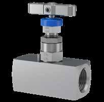
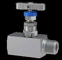
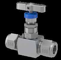
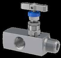
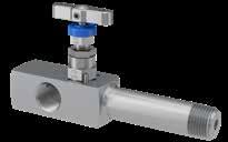
Hand Valves - HNV Series - Straight Pattern 21
Hand Valves - HNAV Series - Angle Pattern 22
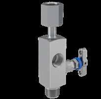
Gauge Valves - HNVV Series - Single Block Gauge Vent Valves 23
Gauge Valves - HGV Series - Multi-port Gauge Valves 24
Rising Plug Valves - HRPV Series................................................................................................................................................. 25
Ordering information 26
2-Valve Manifolds - Remote/line Mount 28
Introduction 28
2-Valve Manifolds - HNL Series - Remote/line mount - long pattern 29
2-Valve Manifolds - Remote/line mount 30 Ordering Information - 2-Valve Manifolds - Remote/Line Mount ................................................................................................ 32
Mounting Brackets for Remote/line Mount Manifolds and Gauge Valves .................................................................................. 34 3 and 5-Valve Manifolds - Remote/line Mount 35
Introduction 35
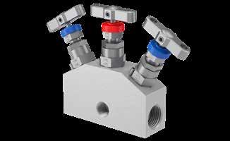
3-Valve Manifolds - Remote/line Mount 36
5-Valve Manifolds - Remote/line Mount 37
Ordering Information - 3 and 5-valve Manifolds - Remote/line Mount 38
Mounting Brackets for Remote/line Mount Manifolds and Gauge Valves .................................................................................. 40
2-Valve Manifolds - Direct Mount
.................................................................................................................................................... 41
3-Valve Manifolds - Direct Mount 42
5-Valve Manifolds - Direct Mount 44
Ordering information 46
Mounting Brackets for 2, 3 and 5-valve Direct Mount Manifolds 48
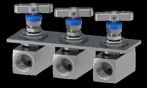
Base Connected Manifolds Especially Suited For Enclosure Mounting 50
Instrument Enclosure Solutions
...................................................................................................................................................... 54
Manifolds for 2051/3051 CoplanarTM Transmitters 55
Essential Manifold Accessories 61
Other Manifold Products 64
Customer Specific Manifold Solutions 66
Complementary Products for Complete Installation Solutions 68
3
Contents
PROCESS INSTRUMENTATION


VALVE AND MANIFOLD SOLUTIONS

Welcome to the Parker Superior Advantage for your process to instrument hook ups.
Wholly designed and manufactured from decades of development, experience and knowledge from within our ISO 9000 compliant UK facility, the Parker H-series valve and manifold solutions range enjoys world leading recognition for quality, reliability and value.

Selection can be made from a comprehensive range of bonnet assemblies, body configurations and styles with a variety of connections and material options to suit all your applications, optimising your installation and improving operation.
In addition to producing these valves and manifolds with your choice of connections, all the products offered in this catalogue are available (as standard) with the superior advantage of integrated tubing connections. The specification of the world renowned and universally acceptable Parker compression type connections will improve system performance, increase safety, reduce size and weight and simplify installation which ultimately reduces overall user costs.
IntroductionThe top five target markets for Parker Instrumentation are shown below, but Parker manifold solutions are suitable for the widest range of process measurement and control applications in a diverse spectrum of industries.
Continuous product development may from time to time necessitate changes in the details contained in this catalogue. Parker reserves the right to make such changes at their discretion and without prior notice. All dimensions shown in this catalogue are approximate and subject to change.
Every effort is made to provide sufficient, clear and accurate information to allow the correct selection of product from this catalogue, but ultimately it is the system designer’s or user’s responsibility to ensure selected product is suitable for the intended application. Should you require further information please do not hesitate to contact your local Parker support.
With thousands of distributor outlets and stores worldwide, and hundreds of Parker personnel and locations, Parker also offers the superior advantage of supply and support in your locale.
Parker EHS Vision Statement:
Parker recognizes, and believes, in the importance of safeguarding natural resources and the global environment. We are committed to our employees, our communities, and our customers: their health, safety and understanding of the need for environmental stewardship. We are committed to the concept of continuous improvement in environmental performance. Accordingly, we are committed to the following principles:
• We will seek to comply with environmental, health, and safety laws worldwide.


• We strive to minimize or eliminate the generation of waste.
• We will monitor compliance with environmental, health and safety regulations.


5
Oil & Gas Downstream Oil & Gas PowerGen Industrial Gas Transportation
Upstream
Design
All valves and manifolds are designed to meet the pressure and temperature ratings of ANSI B16.34 Class 2500/Class 4500 as applicable, limited only by selection of gland packing materials. Conformity to the recommendations of MSS SP-99 is also assured.
Relevant codes, standards and specifications
Code/SpecificationDescription
DIN EN61518 / IEC 61518Mating dimensions between differential pressure (type) measuring instruments
ASME B31.1 Process Piping Specification for Pipeline Valves
ASME B16.34 Valves - Flanged, Threaded and Welding End
ASME B16.5
NACE
API
MSS
MSS
ISO
Materials of construction
All materials are purchased from long standing reputable sources, conforming not only to recognised national/ international standards, but also to additional requirements imposed by Parker to assure suitability/usability across the widest spectrum of user applications. A range of techniques and processes including PMI (Positive Material Identification) are used to validate all incoming material supplies, segregation, storage and maintenance of product quality.
Body material options
Titanium
All materials will meet (as applicable) the requirements of NACE MR0103/MR0175 and ISO 15156. They are further supplied as per NORSOK M650/M630 as required.
* Carbon Steel may not be universally available, and if offered, may be restricted to body only. Other materials may be considered but any offer may also be restricted to body only. Please consult with your local Parker support.
General information - materials of construction
6MO Incoloy 825Inconel 625
Tip 17-4PH St.St. Monel K500 Duplex UNS S.32750/32760 Inconel 625 Hastelloy B3 Titanium GR-5 DUPLEX UNS S.32750/32760 Inconel 625Inconel 718
Joint Seal 316 St.St. ASTM A479 Monel M400 6MO Inconel 625 Hastelloy C-276 Inconel 825 6MO Incoloy 825Inconel 625
Packing
/
Gland Adjuster 316 St.St. ASTM A479 316 St.St. ASTM A479 316 St.St. ASTM A479 316 St.St. ASTM A479 316 St.St. ASTM A479 316 St.St. ASTM A479 316 St.St. ASTM A479 316 St.St. ASTM A479 316 St.St. ASTM A479 Handle 316 St.St.316 St.St.316 St.St.316 St.St.316 St.St.316 St.St.316 St.St.316 St.St.316 St.St.
Grub ScrewA4-80 St.St.A4-80 St.St.A4-80 St.St.A4-80 St.St. A4-80 St.St. A4-80 St.St.A4-80 St.St. A4-80 St.St. A4-80 St.St.
Notes:
Max.
• Monel selection down-rates to 5,000 psig (345 barg)
• Titanium selection down-rates to 2,750 psig (190 barg)
• Other materials and option selections can also affect performance ratings. If in doubt, please consult your local Parker support.
Standard and optional specification details
Standard Specification Details
Seat orifice diameter - 4mm
Optional Specification Details
Seat orifice diameter - up to 6mm in some configurations/ styles. See page 14
Flow co-efficient (Cv) - 0.35 6mm: Flow co-efficient (Cv) - 0.5
Metal to metal valve seat and stem tip Alternative soft tip and tip materials. See page 14 100% pressure test. All valves and manifolds are subjected to hydrostatic pressure at 1.1x maximum working pressure for the seat and 1.5x maximum working pressure for the shell
All products supplied in a clean bur and grease free condition suitable for most liquid and gaseous applications
Bodies and bonnets are fully traceable to original material source (certification with unique trace code applied to the bar stock material.
Certification according to BS EN 10204 3.1 for material and pressure test is available
All products are permanently marked as per example below. Manifolds include a line diagram describing the flow paths. Complementary to the marking, bonnet assemblies are all functionally colour coded by the dust caps
Number of turns open to close: 3.5
Alternative pressure test regimes applied to oxygen cleaned and/or low emission products. See page 17
Your other pressure test requirements can be considered
Cleaned suitable for oxygen service. Not every product option is suitable for oxygen service
Alternative levels of traceability and certification are available. Your other requirements can be considered
Certification according to BS EN 10204 3.2 can be available at additional cost, please contact your local Parker support
6mm: Number of
7 6
and
All manifolds include mounting
suitable
brackets
enclosure mounting
mounting brackets
accessories
valves
General Technical Information Material Group Material Designator UNS No. Werkstoff No. Euronorm Equivalent ASTM Material Grade Carbon Steel* A105 UNS 1.0482 19Mn5K03504 A105 Austenitic Stainless Steel 316/316L Dual certified UNS S31600 1.4401X5CrNiMo17-12-2 A479 Gr 316 UNS S31603 1.4404X2CrNiMo17-12-2 A479 Gr 316L Super Austenitic Stainless Steel 6Mo UNS S31254 1.4547X1CrNiMoCuN20-18-7A479/A276 Austenitic-Ferritic Steel (Duplexes) Duplex 22CrUNS S31803 1.4462 X2CrNiMoN22 5 3A479/A276 Duplex 25Cr UNS S32750 1.4410X2CrNiMoN25-7-4A479/A276 UNS S32760 1.4501X2CrNiMoCuWN25-7-4A479/A276 Copper-Nickel Alloy Monel 400UNS N04400 2.436NiCu30Fe ASTM B164 Nickel Alloy Alloy 825UNS N08825 2.4858NiCr21Mo
turns open to close: 3.3 Gauge valves and manifolds do not include plugs as standard Various plugs are available to order. See page 60 Direct mount manifolds include applicable flange face seals
high tensile, zinc plated carbon steel mounting bolts Stainless steel mounting bolts are available. See page 48
holes
for
or
A full range of
and
are available. See pages 40, 48, 60 Mounting for selected hand valves and gauge
is available
ASTM B425 Nickel Alloy Alloy 625UNS N06625 2.4856NiCr22Mo9Nb ASTM B446
Nickel Alloy Alloy C276UNS N10276 2.4819NiMo16Cr15W ASTM B574
TitaniumGrade 2UNS R50400 3.7075Ti-II ASTM B348
Pipe Flanges and Flanged Fittings
MR0175 / ISO 15156 Petroleum and Natural Gas Industries - Materials for use in H2S - containing Environments in Oil and Gas Production
598 Valves Inspection and Testing
5208 Industrial Valves - Pressure Testing of Metallic Valves
API
ISO
607 / ISO 10497 Fire Test of Soft-Seated Quarter Turn Valves Fire type-testing requirements
Standard Marking Systems for Valves, Fittings, Flange and Unions
SP-25
Pressure Testing of Valves
SP-61
Instrument Valves
MSS SP-99
15848 Industrial valves— Measurement, test and qualification procedures for fugitive emissions
Luft TA-Luft 2002, Absatz 5.2.6.4 und VDI 2440 (Ausgabe Nov. 2000), Absatz 3.3.1.3 erfüllen Item Material St.St.MonelDuplex Super Duplex Hastelloy Titanium 6MOIncoloyInconel
316 St.St.. ASTM A479 Monel M400 Duplex UNS 31803 Super Duplex UNS S32750/32760 Hastelloy C-276 Titanium GR-2
TA
Body
P.T.F.E.
Graphite P.T.F.E. / Graphite P.T.F.E. / Graphite P.T.F.E. / Graphite P.T.F.E. / Graphite P.T.F.E. / Graphite P.T.F.E. / Graphite P.T.F.E. / Graphite P.T.F.E. / Graphite Thrust Bush316 St.St316 St.St316 St.St316 St.St 316 St.St316 St.St316 St.St316 St.St316 St.St Stem 316 St.St. ASTM A479 Monel M400 Duplex UNS 31803 Super Duplex UNS S32750/32760 Hastelloy C-276 Titanium GR-2 6MO Incoloy 825Inconel 625
Cap LDPEColoured LDPEColoured LDPEColoured LDPEColoured LDPEColoured LDPEColoured LDPEColoured LDPEColoured LDPEColoured Lock
ASTM
Monel M400 Duplex UNS
Super Duplex UNS
Hastelloy
Titanium
Dust
Nut316 St.St.316 St.St.316 St.St.316 St.St.316 St.St.316 St.St.316 St.St.316 St.St.316 St.St. Bonnet 316 St.St.
A479
31803
S32750/32760
C-276
GR-2 6MO Incoloy 825Inconel 625
Working Pressure 6,000 psig (414 barg) High Pressure Range 10,000 psig (689 barg) P.T.F.E. Packing Max. 260oC (500oF) Graphite Packing Max. 583oC (1000oF)
Introduction
Parker valve and manifold products are available with a wide array of connection types and sizes. These products are manufactured at the highest quality to applicable standards, utilising state of the art machinery and processes backed by decades of expertise.
The following pages detail the standard connections available. Other connection types can be considered. If you can’t find the best connection for your application, please contact your local Parker support. Please note – not all connection types and sizes will be universally possible across the entire product range.
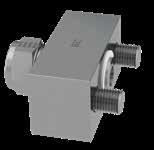
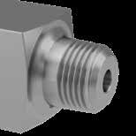
Integral tubing connections – A Parker Superior Advantage
For the ultimate in safety, reliability, speed and ease of installation all valves and manifolds can be specified with solutions offering integral tube connection utilising Parker A-LOK® (Two Ferrule) or CPITM (Single Ferrule) compression fitting technology.
For full details of the A-LOK® and CPITM technologies, please see Catalogue ref. 4190-FMTG.

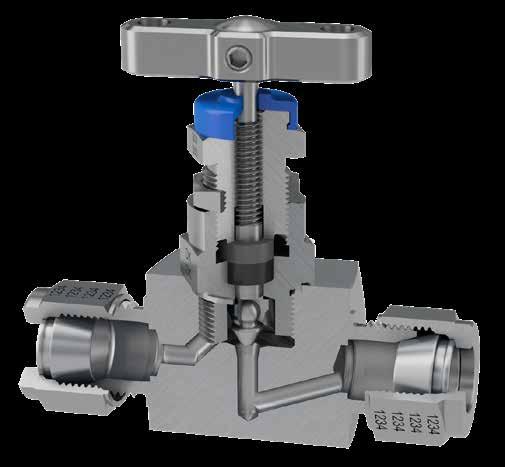
As standard, hand valves and gauge valves are offered with the traditional external thread and nut or inverted (internal thread) design to inlet and outlet connections. Other ports (such as vent) are offered with Parker unique PTFree connectTM solution (see p. 10).
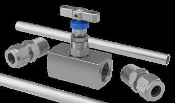
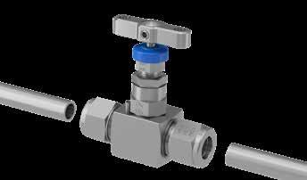
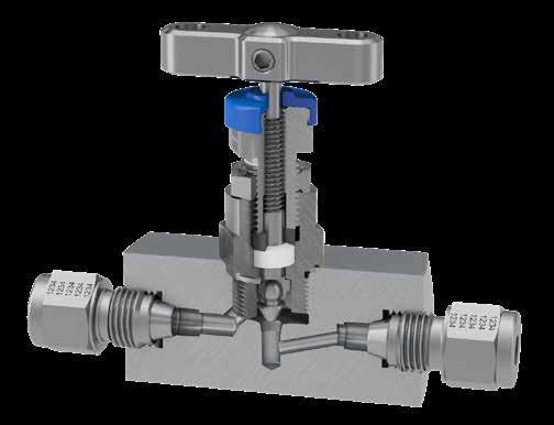
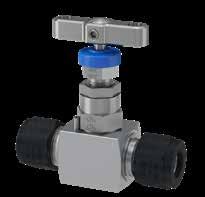
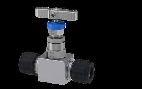
HNV series hand valve with traditional type fully integrated tube fitting connection.
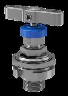
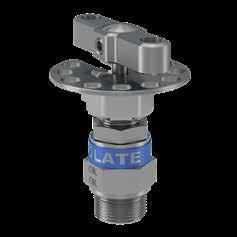
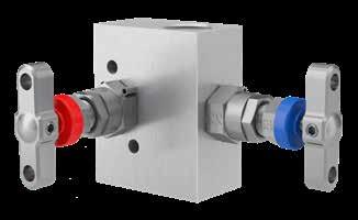
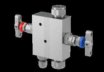
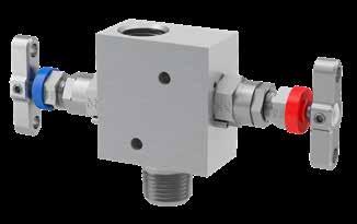
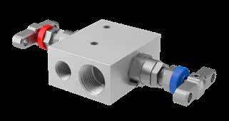
As standard, manifolds are offered with PTFree connectTM style solutions to the inlet connections for direct mount types and also to the outlet connections for remote mount types.
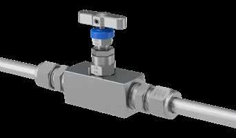
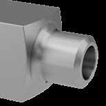
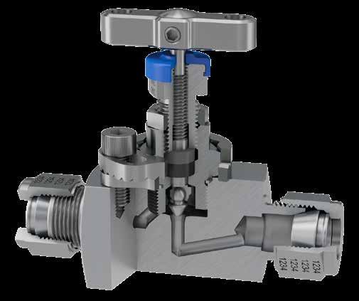
Other ports (such as vent) are also offered with Parker Instrumentation’s unique PTFree connectTM solution. Some manifold types can be offered with the inverted design to inlet and outlet connections as applicable.
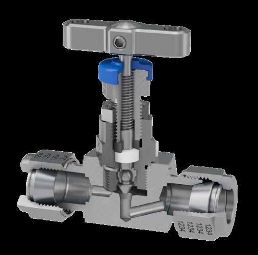
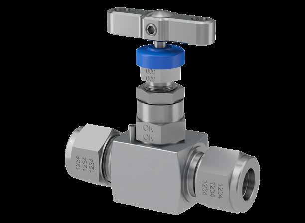
HNV series hand valve with the unique Parker fully integrated inverted tube fitting connection.
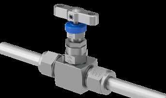
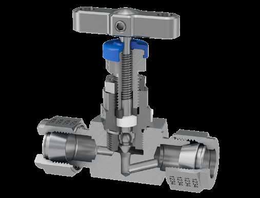
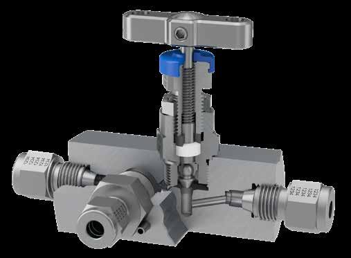
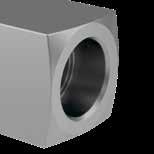
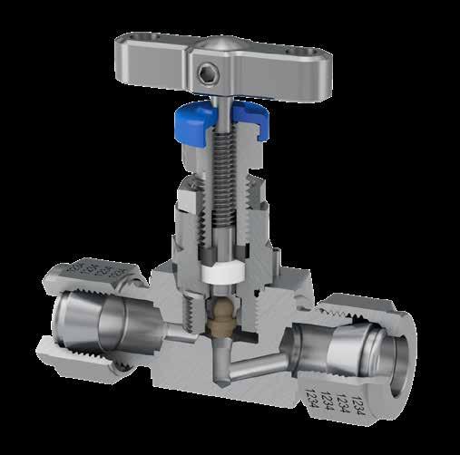
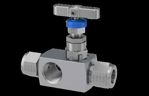
HNV series gauge vent hand valve with inverted tube fitting to inlet and outlet connections with Parker PTFree connectTM tube fitting connection to the vent.
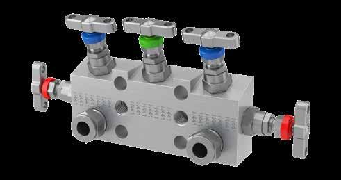
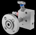
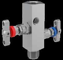
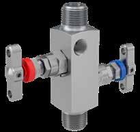
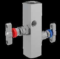
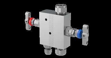
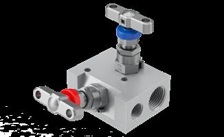
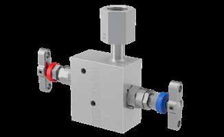
5-valve direct mount manifold for differential pressure applications having inlet and vent connections provided through the use of PTFree connectTM tube fittings.
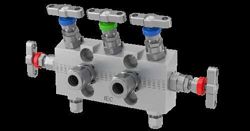
5-valve direct mount manifold having the Parker superior advantage input connections provided through inverted tube fitting connections. Vent can also be specified as threaded or PTFree connectTM.
Why the Superior Advantage of an integrated tube connection?
Consider the following simple example with a typical hand valve.
ComponentCost
Needle valve 1x
Fittings (2) 1.1x Sealant/Tape0.01x Labour 0.15x TOTAL 2.26x
Example shown is the Parker Superior Advantage fully integrated tube fitting connection.
ComponentCost
Needle valve 1.6x
Fittings (2) 0x Sealant/Tape0x Labour 0.05x TOTAL 1.65x Integrated tube
•
9
8
Connections
Example shown is the widely utilised normal specification of a valve and individual tube fittings to achieve the installation.
Average 25% saving on installed cost
Average 55% saving on
time
Zero
connections deliver: •
•
installation
•
rework
Significantly
improved safety and system integrity
Tube end dimensional data
Other connections
Size
1 1/1610-32.435/16.052.34
2 1/85/16-20.607/16.093.50
3 3/163/8-20.641/2.125.54
4 1/47/16-20.709/16.187.60
5 5/161/2-20.735/8.250.64
6 3/89/16-20 .76 11/16 .281 .67
8 1/23/4-20.877/8.406.90
105/87/8-20.87 1 .500.96
123/41-20.871-1/8.625.96
147/81-1/8-20.871-1/4.7501.03
16 1 1-5/16-201.051-1/2.8751.24


201-1/41-5/8-201.521-7/81.091.61
241-1/2 1-15/16-20 1.772-1/41.341.96
32 2 2-5/8-202.472-3/41.812.65
Notes:
• Dimensions C and D are shown in the finger-tight position.

• † Average value
• Dimensions for reference only, subject to change.
PTFree connectTM
Size No.
Milimeters
Tapered Pipe Threads - Male and Female
Tube O.D.
2 2mm5/16-2015,312,01,712,9
3 3mm5/16-2015,312,02,412,9
4 4mm3/8-2016,112,02,413,7
6 6mm7/16-2017,714,04,815,3
8 8mm1/2-2018,615,06,416,2 1010mm5/8-2019,518,07,917,2 1212mm3/4-2022,022,09,522,8 1414mm7/8-2022,024,011,124,4 1515mm7/8-2022,024,011,924,4 1616mm7/8-2022,024,012,724,4 1818mm1-2022,027,015,124,4 2020mm1-1/8-2022,030,015,926,0 2222mm1-1/8-2022,030,018,326,0 2525mm1-5/16-2026,535,021,831,3
Many users desire the elimination of taper threads and their associated sealant.
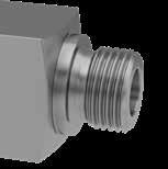
The PTFree connect™ system enables users to assemble tube lines to any of the manifold ports without the need for PTFE tape or liquid sealant.
The PTFree connect™ connection can be applied to any of the manifolds featured in this catalogue. These will be factory fitted, pin locked and pressure tested.
PTFree connect™ enables angled tube connections to be swivelled to achieve optimum tube alignment. Assembly to the tube connector is achieved by tightening the standpipe nut one-quarter turn from the finger tight position.
Manifolds can also be supplied with male connectors using the same thread form as the PTFree connect™. They are provided factory fitted, pin locked and tested.
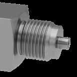
Some size restrictions may be necessary due to the close proximity of some connections and the across flat hexagon dimensions. As a guide, PTFree connect™ for inlet and outlet can be up to 1/2” or 12mm o/d., drain/bleed connections should be restricted to 1/4” or 6mm. For PTFree connect™ male connectors inlet and outlet should be restricted to 3/8” or 10mm and 1/4” or 6mm o/d for drain/bleed.
Tube sizeDimension (A)
6mm22.26mm0.88”
1/4”24.80mm0.98”
10mm/3/8” 26.40mm1.04”
12mm/1/2”32.10mm1.26”
10
Tube sizeDimension (A)
6mm26.90mm0.95”
1/4”24.10mm0.84” 10mm/3/8” 27.70mm1.09” 12mm/1/2”30.30mm1.20”
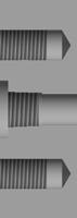
NPT Tapered Thread


NPT Tapered Thread conforming to ASME B1.20.1 with enhanced manufacturing tolerance for optimal assembly and inspected by three step gauging with Parker enhanced tolerancing to ANPT requirement per ASTM SAE AS71051.
Parallel Pipe Threads - Male and Female
BSP Parallel Thread – Default standard (Code R)


BSP Parallel Thread conforming to BS2779, ISO 228/1+2, DIN 3852. Not available on all product/ model types, please consult with your local Parker support.


Weld Connections
Socket Weld (Code SW/MSW)


Female or male Socket Weld connection suitable for pipe conforming to ASME B16.11, EN12760.
BSP Tapered Thread (Code K)
BSP Tapered Thread conforming to BS21, ISO7/1 (R ½ - Male. Rc ½ Female) with enhanced manufacturing tolerance for best optimal assembly and inspected using gauging system to BS21.
BSP Parallel Gauge connection type – Optional (Code RD)
According to DIN 16284/16288/ DIN EN 837.
Thread conforming to BS2779, ISO228/1+2, DIN 3852. Not available on all product/model types, please consult with your local Parker support.


Butt Weld (Code BW)
Butt Weld connection suitable for pipe conforming to ASME B16.25, EN12627.

Notes:
• Valves with female socket weld connections will be of the same length as per the equivalent NPT pipe threaded variants.
• Valves with male socket weld connections will, as standard, have a stub length increase of 1/2” (13mm) when compared to the male pipe threaded equivalent variants.
Other Notes:
Notes: Valves with butt weld connections will, as standard, be of the same length as per the equivalent male NPT pipe threaded variants. Optional
• For valves with welded connections, special consideration must be given to the installation/welding process. Care must be taken to ensure that the central valve body and bonnet assembly sections are not harmed by the process itself and to further protect these elements from injurious heat transfer.
• Connection ratings: Certain weld connections can impact published performance ratings of the manifold. Care should be taken in the selection of connections to ensure they meet application expectations for performance. For example: Butt weld or tube fitting connections with a thinner wall section, may result in a reduced pressure performance capability when compared to that of the published. Please consult relevant Parker publications or consult with your local Parker support.
Flange Connections
Process Flange
Flange connections can be considered if conforming to ANSI B16.5 and executed in various ways. Please consult your local Parker support. Not available on all product types.
Instrument Flange (Code HK) DIN/IEC 61518 compliant instrument (kidney/oval) flange connections.
10 11
Connections
Straight
H Hex E Dia. †D Tube
No. Inches Tube O.D.
Thread†C
Ins. Depth
Straight
H Hex E
†D Tube Ins.
Thread†C
Dia.
Depth
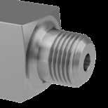
PTFree connect™ tube stub (Code PF)
connect™ male connectors (Code PFC) A A
PTFree
male
welds or
welds can be offered with stub length of 75mm
SCALE1:1 SCALE2:1 C OPTIONALLENGTHS 75.0 and 100.0mm 75mm or 100mm
lengths: If requested,
socket
butt
or 100mm.
SECTIONC-C SCALE1:1 DETAILE SCALE2:1 C PipeSize(NB)Length'A' 4[1/4"NB] 6[3/8"NB] 8[1/2"NB] 32 12[3/4"NB] 35 Pipe sizeDimension (A) 4 (1/4" NB) 29 6 (3/8" NB) 29 8 (1/2" NB) 32 12 (3/4" NB) 35 A
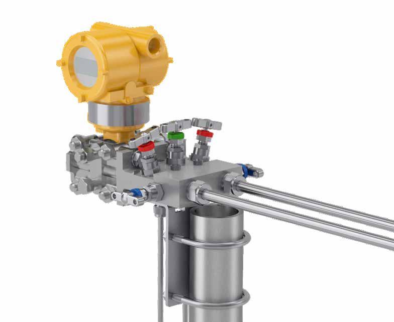
Transmitter flange connections
gas or vapours. The maximum allowable temperature of 120°C (248°F) considers the requirement that manifolds and transmitters need to be protected against undue heating by hot media. This requirement should be achieved by using adequate hook-ups or by instrument impulse lines with sufficient length. However, Parker confirms that H series manifolds can be used for temperatures up to 538°C (1,000°F) with graphite gland packing and up to 260°C (500°F) with PTFE gland packing.
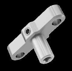
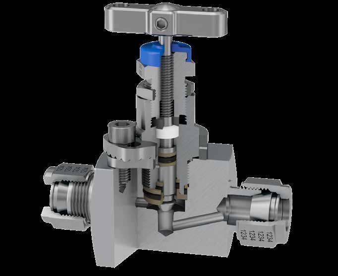
Bonnet Assemblies
Standard bonnet design
Class 2500 (6,000 PSI) and Class 4500 (10,000 PSI)
For safe, reliable and repeatable performance ReferenceDescription
Ergonomic ‘T’ bar style handle with positive retention


Dual purpose dust cap provides functional identification
anti-vibration gland lock nut
low torque back seating stem
metal body bonnet seal
Gland thrust bush ensures uniform packing compression and tight sealing
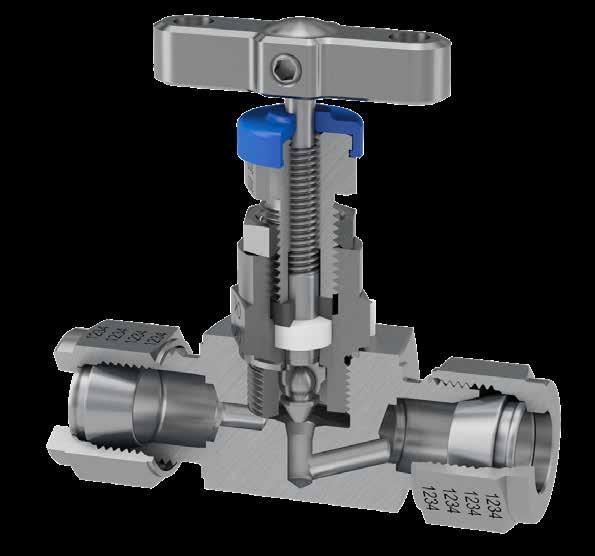
Annealed sealing washer guarantees 100% sealing assurance
Self centering, non-rotating stem tip guarantees bubble tight shut off
Material traceability for major pressure containing components
1. Emerson CoplanarTM transmitter design. Parker offers a full range of specifically suitable manifolds for this type. See pages 55-60.
2. There is a limited range of other higher working pressure transmitters by some manufacturers, where the interface is proprietary by design (Example: Yokogawa EJX 440A/EJA 440E). Parker is able to provide manifold designs that are complementary to those products. Please consult your local Parker support.
SECTIONA-A SCALE1.25 DETAILB SCALE1.25 B 54.0 0.1 41.3 0.2 11.8 - 0.0 0.2 + 25.2 2.3 1.9 1.8 - 0.0 0.1 + 2.4 - 0.3 0.0 + 20.65 0.1 18.0 - 0.1 0.0 + 25.2 - 0.1 0.0 + SECTIONB-B SCALE1.25 DETAILC SCALE1.25 C 54.0 0.1 41.3 0.2 11.8 - 0.0 0.2 + 2.0 - 0.0 0.1 + 20.65 0.1 19.9 - 0.1 0.0 + 25.5 - 0.1 0.0 + 12
DIN/IEC 61518 As
outlet
Within DIN/EN 61518 the manifold-transmitter interface is rated for maximum allowable working pressure of 413 bar (6,000 psi) and maximum allowable temperature of 120°C
liquids,
inlet to manifold / transmitter interface DIN EN 61518 / IEC 61518 Type B (Standard) Type A (Optional) Max. Allowable Working Pressure 413 bar (6,000 PSI) 413 bar (6,000 PSI) Temperature range PTFE: -10OC to +80OC (14OF to 176OF) Graphite: -40OC to +120OC (-40OF to 248OF) PTFE: -10OC to +80OC (14OF to 176OF) Graphite: -15OC to +120OC (5OF to 248OF) Seal ring Flat Ring 25.4 x 20 x 2.7 Material: PTFE Flat Ring 25.4 x 19.9 x 2.9 Material: Graphite Flat Ring 24 x 17.7 x 2.7 Material: PTFE Flat Ring 25.1 x 18.0 x 2.9 Material: Graphite Min. Thread Engagement 9mm 9mm
-
standard, Parker manifolds have inlet and
interface connections in full accordance with DIN/IEC 61518. For the Manifold to Transmitter interface, the type B connection is standard – type A is optionally available.
(248°F) for
Process
61518.
standard:
Connection at the manifold acc. to DIN/IEC
Important Note - there are some exceptions to the IEC 61518
2
3Compensatory
4Secure
5Anti-blowout
6All
7
8
9
10
13
0 100 200 300 400 500 (32) (212) (392) (572) (752) (932) 10,000 (690) 8,000 (552) 6,000 (413) 4,000 (275) 2,000 (138) 0 Pressure psi (bar) Temperature °C (°F) A B B CA Notes: • As standard, all metallic parts are 316 Stainless Steel. Optional materials are available, please see page 6. • For products specified in optional materials, non-wetted parts will be 316 Stainless Steel as standard. • 6,000 PSI bonnet thread is M16; 10,000 PSI bonnet thread is M18. ReferenceDescription A - AGraphite packing A - BPTFE packing B - B6,000 PSI (414 bar) standard PTFE packing B - C 6,000 PSI (414 bar) standard Graphite packing Notes: • Pressure and temperature ratings shown are maximum possible values. Continuous operation at the maximum ratings will reduce life expectancy. • Pressure and temperature ratings can be derated by certain connection types or materials of construction. 1 3 6 2 4 5 7 9 10 8 Connections Parker manifold outlet to transmitter interface DIN EN 61518 / IEC 61518 Type B and Type A Type B Type A 20.65±0.1 41.3±0.2 ø18.0+0.0 -0.1 ø25.2+0.0 -0.1 2.4 +0.0 -0.3 2.0 +0.1 -0.0 ø25.5+0.0 -0.1 ø19.9+0.0 -0.1 ø11.8+0.2 -0.0 54.0±0.1 1.8 +0.1 -0.0 54.0 0.3 41.3 0.2 15.0 18.5 - 0.0 0.3 + 2.5 - 0.0 0.5 + 1) 1)Threadedoptionfortransmitters-plug/ventvalve 20.65 0.2 54.0±0.3 ø18.5+0.3 -0.0 2.5+0.5 -0.0 41.3±0.2 ≥15.0 20.65±0.2 1 ReferenceDescription 1 Threaded option for transmittersplug/vent valve
1
adjustable gland
Pressure vs temperature
Bonnet Assemblies
Larger bore bonnet design
Class 2500 (6,000 PSI) and Class 4500 (10,000 PSI)
Features
• 6mm seat orifice size, allowing the provision of larger 5mm or 6mm flow passages
• Ideal for applications with dirtier/denser service media and/or those prone to blocking in small bore installations
• Can enhance other aspects of performance and measurement accuracy
• Will result in the use of larger body material sizes
• Not possible for all styles and types of product
• All other technical information remains unchanged from standard
Fire safe bonnet design - Class 2500 (6,000 PSI)
Features
• Specifically designed & developed to meet exacting industry requirements, products incorporating this Bonnet Design conform to BS 6755 Part 2, API 6FA / API607. For further details contact your local Parker support.
• 100% fire safe design certified, many typical actual 3rd party test certificates are available for review
• Available for most product styles and types
• Some material selections are restricted
Soft seat tip bonnet design
Features
• Available in the 4mm orifice size only, this PEEK seat tip option is available for all product styles and types
• Ideal for clean gaseous or other services where tight bubble tight shut off with minimum effort is required
• Suitable for temperatures up to 204oC and pressures up to 10,000 psi at reduced temperature, as per graph
• For larger bore requirements Parker Instrumentation recommends Rising Plug valve
Pressure vs temperature
Power plant bonnet design
Compliant to ANSI B31.1
– Class 2500 (6,000 PSI)
Features
• Available in a select range of body styles and types. Please consult your local Parker support
• Designed specifically to meet the requirements of ANSI B31.1 (Power Plants) and B31.3 (Petrochemical Plants) including materials of construction, these bonnet assemblies are Graphite packed for higher temperature service
• Suitable for temperatures up to 538oC and pressures up to 6,000 psi at reduced temperature, as per graph
• Unique patented Tru-Loc® safety bonnet lock further enhances security in application
Pressure vs temperature
Pressure psi (bar) -18 38 93 149 204 260 316 371 427 482 538
7,000 (483) 6,000 (414) 5,000 (345) 4,000 (276) 3,000 (207) 2,000 (138) 1,000 (69) 0 Temperature °C (°F)
14
15
(0) 100) (200) (300) 400) (500) (600) 700) (800) 900) 1,000)
0 100 200 300 400 500 (32) (212) (392) (572) (752) (932 10,000 (690) 8,000 (552) 6,000 (413) 4,000 (275) 2,000 (138) 0 Pressure psi (bar) Temperature °C (°F) A C ED ReferenceDescription A - DPEEK tip C - E PCTFE tip - Temperature limit 150°C (302°F) at 3,000 psi (207 bar)
Bonnet Assemblies
Rising plug bonnet design
Low emission bonnet design
Features
• HRPV valve is unique to Parker and is patent protected
• Non-rotating plug/tip
• Dynamic response moulded seat insert with guaranteed alignment
• Standard straight through orifice size 1/4” (6.4mm)
• Rolled spindle operating threads
• Straight through flow path
• Standard multi-port gauge style available as standard
• Other styles can be considered - please consult the factory
• Bi-directional flow
• Backstop spindle for blowout prevention and minimal atmospheric leakage
• Low torque operating T bar handle
• Externally adjustable gland
• Full range of head options available
Pressure
Tru-Loc® safety bonnet lock
• Dust cap to prevent ingress of contamination to operating thread
• Bonnet locking pin fitted as standard
• Suitable for temperatures up to 204oC and pressures up to 10,000 psi at reduced temperature, as per graph
TA-Luft compliant
As standard, products fitted with the Parker Instrumentation standard bonnet assembly are bubble tight in service and have been proven to meet the requirements of TA-Luft 2002, Absatz 5.2.6.4 und VDI 2440 (Ausgabe Nov. 2000), Absatz 3.3.1.3 erfüllen.

IS0 15848 compliant
From 2007 EU’s IPPC directive 96/61/EC legislates for the minimisation of pollution from industrial sources (Many other regions and countries have similar legislation). An important part of this legislation is reducing Ultra-Low emissions. According to the IPPS, all plants and factories which fail to comply with the standards set by the directive, may face closure.

The legislation introduced a concept of Best Available Technique (BAT), urging plants to find the best available solution for reducing Ultra-Low emissions throughout all processes. With respect to valves, ISO 15848 parts 1 and 2 were developed to aid companies to meet the legislation.
Part 1 covers the classification system and qualification procedure for type testing of valves. The standard specifies three tightness classes of leakage with respect to stem sealing diameter. These classes are class A, B and C; class A having the smallest environmental leakage. Each class level is one hundred fold lower than the class above i.e. a class B product may have a leakage of 100 times that of a class A product. The standard also specifies the duty that the valve has been tested to.
Parker Instrumentation specifically developed an H series Bonnet Assembly design with class A approval to ISO 15848-1. Classed ‘FE’, products specified with these bonnet assemblies are certified as ISO FE AH-C01-SSA1-t(RT,180°C)-ANSI2500-ISO 15848-1. These products are further classified as meeting the ISO 15848-1 standard with the following criteria;
• Class A tested with Helium
• Endurance class C01 – a mechanical valve which has been tested throughout 500 mechanical actuations with two thermal cycles

• Temperature class RT-180°C – fully thermal cycled and tested from -29°C to +180°C pressure class ANSI 2500 – 6000 psi in 316 stainless steel.
Part 2 of the standard covers production acceptance testing of valves. This production testing can only be carried out to product which has already been approved to part 1 of the standard. Parker Instrumentation can offer production testing and certification to a sampling percentage specified by the purchaser. A third party witnesses can also be considered.
Available as standard on ANSI/ASME B31.1 manifold versions, the unique Parker Tru-Loc® security locking system is applied to the body to bonnet interface but can also be applied to many other screwed component interfaces. Extensive tests have proven that threaded connection interfaces secured with Tru-Loc® guarantee 100% security in preventing movement between connected components. In the H series manifolds it prevents loosening or removal of the bonnet assembly by any means.
16
vs temperature ReferenceDescription A - APEEK Seat 0 100 200 300 400 500 (32) (212) (392) (572) (752) (932) 10,000 (689) 8,000 (552) 6,000 (414) 4,000 (275) 2,000 (138) 0 Pressure psig (bar) A A Temperature °C (°F)
Low emission bonnet design
Bonnet
Features
• Tightness class A≥1 x 10⁻⁶ mg.s-1.m-1
• Maximum cold working pressure rating 6,000 psig (414 barg)
• Temperature rating -29˚C to 180˚C (-20˚F to 356˚F)
• ISO15848-1 prototype tested using global helium vacuum method
• Performance class –ISO FE AH-C01-SSA1-t(RT,180°C)-ANSI2500-ISO 15848-1
• Production testing and certification available on request )
• O – ring material grade is Fluoroelastomer FKM Tetrapolymer, specially formulated for explosive decompression (ED) resistance. These seals are qualified to the stringent NORSOK M-170 standard covering both ED resistance and sour gas (H2S) ageing tests
• Available for most product styles and types
• Also meets the requirements per; TA-Luft according to VDI 2440 as tested by TUV SUD Industrie Service GMBH performing better than a leakage rate of VDI 2440 = 10 -4 mbar .l /s . m
Pressure vs temperature 0 60 120 180 (32) (140) (248) (356) 6,000 (413) 4,000 (275) 2,000 (138) 0 Temperature °C (°F) A B B A C C E ReferenceDescription 1Positive
2“T”
3Dust
4Gland
5Gland
6Thrust
7Gland
8Valve
9Anti
10Anti
ring 11Elastomeric
12Anti-extrusion
13Elastomeric
14Bonnet
15Spindle
Pressure psi (bar) 19 ReferenceDescription A - AGraphite packing A - BPTFE packing B - B6,000 PSI (414 bar) standard PTFE packing B - C 6,000 PSI (414 bar) standard Graphite packing A - DPEEK tip C - EPCTFE tip 1 3 2 10 4 5 7 6 9 11 15 13 12 14
handle retention
bar
cap
packing adjuster
adjuster lock nut
bush
packing (adjustable)
bonnet
blow-out spindle
extrusion
o-ring (stem seal)
ring
o-ring (body seal)
end cap
tip
18
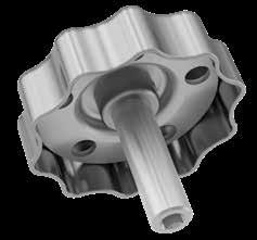
assembly options Available as a factory fit or as retrofit, these useful bonnet assembly options are provided in all 316 Stainless Steel material. For locking options padlocks are not provided but the hole size in all cases is 6mm (0.24”). To obtain factory fit options your specified product part number must be suffixed with the additional option part numbers
below. Some options can be combined. Handwheel Lockable handwheel Anti-tamper spindle Key T bar handle locking Bonnet Assemblies Anti-tamper handwheel Panel mounting Retrofit Kit Part Number Factory Fitted Suffix KITTHLHL Retrofit Kit Part Number Factory Fitted Suffix With Key KITAK ATK Without Key KITATAT Retrofit Kit Part Number Factory Fitted Suffix KITPMPM Hole Diameter 26mm (1.02”) Panel Thickness Max. 5mm (0.20”) Min. 2.3mm (0.09”) Min. distance for panel mount spacing 51mm (2.00”) Key only Part Number ATHWKEY Key only Part Number ATHKEY Retrofit Kit Part Number Factory Fitted Suffix KITTHWHW Retrofit Kit Part Number Factory Fitted Suffix KITLHWLHW 8
as
Hand Valves & Gauge Valves
Introduction
Following years of valve design and development, the Parker needle pattern hand and gauge valves range is one of the most comprehensive to be found. The valves are available to users from a wide market spectrum and suitable for all industries and applications.
In combination with Parker A-LOK® or CPITM compression tube fitting technologies, a superior advantage is gained allowing users to eliminate threaded connections and reducing leak paths whilst offering superior installation and operational performance.
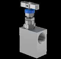
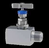
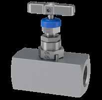
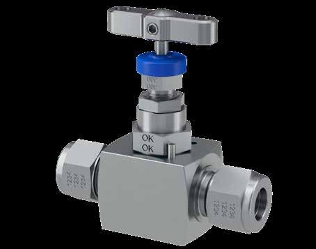
Hand Valves - HNV Series
Straight pattern
HNV* - Integral A-LOK® connections - up to 6,000 PSI
InletOutlet Dimension
A-LOK® A-LOK® A mm (inch) B mm (inch) C mm (inch)
1/4”1/4”67.5 (2.66”)25.4 (1.00”)76.2 (3.00”)
1/2”1/2”76.2 (3.00”)25.4 (1.00”)76.2 (3.00”)
With their small ports and needle/plug stem tip, Parker hand valves allow precise regulation of flow in low flow applications for a wide variety of media.
These hand valves are widely used in situations where the flow must be gradually brought to a halt and at other points where precise adjustments of flow are necessary or where a small flow rate is desired. They can be used as both on/off valves and for throttling service.
Example shown: Multi-port gauge valve with Parker Superior Advantage integral A-LOK® tube fitting connections.
They are used in every industry in a wide range of applications - anywhere where accurate and secure control or metering of steam, air, gas, oil, water or other non-viscous liquids is required.
Utilising these same attributes, the Parker needle pattern gauge valves will be found controlling flow into a vast array of measurement and analysis instrumentation such as pressure gauges, transmitters, switches and more. With additional functionality these gauge valves also allow users to provide vent, drain or blow down routines to their process and/or the ability to attach additional instruments and accessories.
Example shown is a Hand valve with Parker integral CPITM tube connections.
We are confident you will find a valve style, type and connection option to suit your applications, but should you require something different please contact your local Parker support.
HNV* - Integral CPITM connections - up to 6,000 PSI
InletOutlet Dimension
CPITM
1/4”1/4”67.5 (2.66”)25.4 (1.00”)76.2 (3.00”) 1/2”1/2”76.2 (3.00”)25.4 (1.00”)76.2 (3.00”)
6mm6mm67.5 (2.66”)25.4 (1.00”)76.2 (3.00”) 12mm12mm76.2 (3.00”)25.4 (1.00”)76.2 (3.00”)
Integral connections - up to 10,000 PSI
A limited range of integral connections for 10,000 PSI is available as tube selection can adversely affect overall product ratings. Please consult your local Parker support.
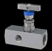
HNV* - Female threaded - NPT
(3.25”)
(3.25”)
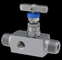
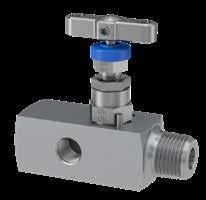
HNV* - Male x Female threaded - NPT
6mm6mm67.5 (2.66”)25.4 (1.00”)76.2 (3.00”) 12mm12mm76.2 (3.00”)25.4 (1.00”)76.2 (3.00”) Notes:
21
20
ReferenceDescription 1Locked grub screw 2“T” bar handle 3Dust cap 4Gland packing adjuster 5Gland adjuster lock nut 6Valve bonnet 7 Integral A-LOK® connection 8Body 1 3 4 5 6 7 8
A B C
given for finger tight nuts and ferrules.
• Dimension “A”
in open position.
• Dimension “C”
CPITM A mm (inch) B mm (inch) C mm (inch)
Pressure (PSI) InletOutlet Dimension FemaleFemale A mm (inch) B mm (inch) C mm (inch) 6,000 1/4” NPT 1/4” NPT 54.0 (2.13”)28.6 (1.13”)79.4 (3.13”) 3/8” NPT 3/8” NPT 54.0 (2.13”)28.6 (1.13”)79.4 (3.13”) 1/2” NPT 1/2” NPT 63.5 (2.50”)28.6 (1.13”)79.4
C mm (inch) 6,000 1/4” NPT 1/4” NPT
1/2” NPT 1/2” NPT
10,000 1/4” NPT
NPT
1/2” NPT 1/2” NPT
A B C A B C A B C A B C
(3.13”) 10,000 1/4” NPT 1/4“ NPT 60.5 (2.38”) 31.8 (1.25”) 82.6
1/2” NPT 1/2” NPT 69.9 (2.75”) 31.8 (1.25”)82.6
Pressure (PSI) InletOutlet Dimension MaleFemale A mm (inch) B mm (inch)
57.8 (2.27”)28.6 (1.13”)79.4 (3.13”)
73.0 (2.87”)28.6 (1.13”)79.4 (3.13”)
1/4”
62.8 (2.47”)31.8 (1.25”)82.6 (3.25”)
76.2 (3.00”)31.8 (1.25”)82.6 (3.25”)
2
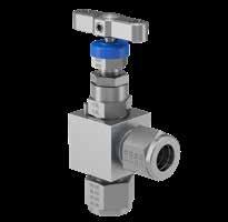
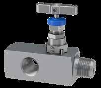
Angle pattern
HNAV* - Integral A-LOK® connections - up to 6,000 PSI
InletOutlet Dimension
A-LOK® A-LOK® A mm (inch) B mm (inch) C mm (inch)
1/4”1/4”53.5 (2.10)25.4 (1.00)94.0 (3.70)
1/2”1/2”58.8 (2.32)28.6 (1.13)101.6 (4.00)
6mm6mm53.5 (2.10)25.4 (1.00)94.0 (3.70) 12mm12mm58.8 (2.32)28.6 (1.13)101.6 (4.00)
HNAV* - Integral CPITM connections - up to 6,000 PSI
InletOutlet Dimension
A-LOK® A-LOK® A mm (inch) B mm (inch) C mm (inch)
1/4”1/4”53.5 (2.10)25.4 (1.00)94.0 (3.70)
1/2”1/2”58.8 (2.32)28.6 (1.13)101.6 (4.00)
6mm6mm53.5 (2.10)25.4 (1.00)94.0 (3.70) 12mm12mm58.8 (2.32)28.6 (1.13)101.6 (4.00)
Integral connections - up to 10,000 PSI
A limited range of integral connections for 10,000 PSI is available as tube selection can adversely affect overall product ratings. Please consult your local Parker support.
HNAV* - Female threaded - NPT
InletOutlet Dimension
NPTNPT A mm (inch) B mm (inch) C mm (inch)
1/4” F1/4” F49.5 (1.95)25.4 (1.00)88.3 (3.47)
1/2” F1/2” F54.3 (2.14)28.6 (1.13)101.0 (3.98)
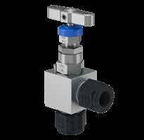
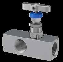
Gauge Valves - HNVV
Single block gauge vent valves

HNAV* - Male x Female threaded - NPT
Notes:
• Dimension “A” given for finger tight nuts and ferrules.
• Dimension “C” in open position.
MaleFemaleFemale A mm (inch) B mm (inch) C mm (inch) 6,000 1/4” NPT1/4” NPT1/4” NPT72.5 (2.85)28.6 (1.13)79.4 (3.13) 1/2” NPT1/2” NPT1/4” NPT85.8 (3.38)28.6 (1.13)79.4 (3.13) 10,000 1/4” NPT1/4” NPT1/4” NPT71.2 (2.80)31.8 (1.25)82.6 (3.25) 1/2” NPT1/2” NPT1/4” NPT85.6 (3.37)31.8 (1.25)82.6 (3.25)
InletOutletVent Dimension
Pressure (PSI)
FemaleFemaleFemale A mm (inch) B mm (inch) C mm (inch)
6,000 1/4” NPT1/4” NPT1/4” NPT63.5 (2.50)28.6 (1.13)79.4 (3.13) 1/2” NPT1/2” NPT1/4” NPT76.3 (3.00)28.6 (1.13)79.4 (3.13) 10,000 1/4” NPT1/4” NPT1/4” NPT69.0 (2.71)31.8 (1.25)82.6 (3.25) 1/2” NPT1/2” NPT1/4” NPT79.5 (3.13)31.8 (1.25)82.6 (3.25)
InletOutletVent Dimension
Pressure (PSI)
MaleMaleFemale A mm (inch) B mm (inch) C mm (inch)
6,000 1/4” NPT1/4” NPT1/4” NPT76.2 (3.00)28.6 (1.13)79.4 (3.13) 1/2” NPT1/2” NPT1/4” NPT94.8 (3.73)28.6 (1.13)79.4 (3.13) 10,000 1/4” NPT1/4” NPT1/4” NPT76.2 (3.00)31.8 (1.25)82.6 (3.25) 1/2” NPT1/2” NPT1/4” NPT94.8 (3.73)31.8 (1.25)82.6 (3.25)
22
23
A B C A B C A B C A B C
InletOutlet Dimension NPTNPT A mm (inch) B mm (inch) C mm (inch) 1/4” M1/4” F49.5 (1.95)25.4 (1.00)91.7 (3.61) 1/2” M1/2” F54.3 (2.14)28.6 (1.13)98.3 (3.87)
HNAV Series
Hand Valves -
Series
conjunction with the measuring instrument, these valves allow for the
of
the instrument for maintenance and/or removal
HNVV* - Male x Female threaded - NPT HNVV* - Female x Female threaded - NPT HNVV* - Male x Male threaded - NPT Notes: • Dimension “A” given for finger tight nuts and ferrules. • Dimension “C” in open position. • For bleed/vent valves and plugs see page 61. A B C A B C
Generally used in
function
venting/draining any process media that may be trapped, following isolation of
purposes.
Pressure (PSI)
InletOutletVent Dimension
A B C
integral swivel
Example shown: HNVV single vent gauge valve with Parker Superior Advantage integral Inverted A-LOK® tube connections to inlet and outlet and with Parker PTFree connectTM to the vent. Products shown here can be supplied with
gauge adaptor as shown on page 24.
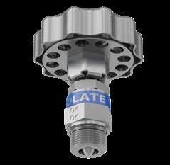
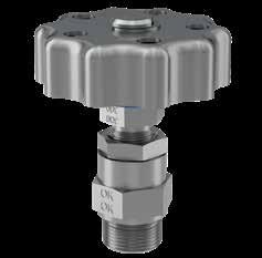
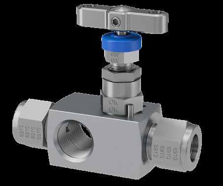
Gauge Valves - HGV Series
Multi-port gauge valves
Parker’s multi-port gauge valves are purpose designed valves for operation up to 6,000 psig (414 barg) and 10,000 psig (689 barg). Featuring standard PTFE gland packing and self-centering non-rotational tip provides bubble-tight seat shut off, giving the user the assurance of safety and performance.

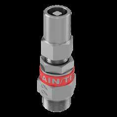
Rising Plug Valves - HRPV Series
These unique, high quality, high performance, low-torque rising plug soft-seated valves have been specifically designed to perform with fluids containing high levels of contamination, such as those frequently found in oil and gas processing facilities. With a straight through flow pattern and 100% repeatable bubble tight shut-off, the valves as standard with PEEK seat will perform up to 10,000 psig (689 barg) with low spindle operating torques.
Example shown: Multi-port gauge valve with integral A-LOK® connections.
Example shown: Hand valve with integral A-LOK® connections.
HGV* - Male x Female (3 outlets) threaded - NPT
HRPV* - Male x Female threaded - NPT
HGV*
HRPV* - Female x Female threaded - NPT
InletOutlet Dimension FemaleFemale A mm (inch) B mm (inch) C mm (inch) 1/4” NPT1/4” NPT60.5 (2.38)31.8 (1.25)88.0 (3.46) 1/2” NPT1/2” NPT69.8 (2.75)31.8 (1.25)88.0 (3.46)
HGVWG*
HRPV* - Male x Female (3 outlets) threaded - NPT
HGV*
Notes:
Dimension “A” given for finger tight nuts and ferrules.
Dimension “C” in open position.
• Swivel adaptor to the outlet is provided through a socket weld, generally conforming to ANSI B16.11.
• Weld connection is a “commercial weld”, completed by a qualified welder. Any specific qualification, certification, documentation or additional NDT, will require to be engineered and quoted extra –please consult your local Parker support.
• Union nut dimensions generally conform to DIN 16284 as it applies to the union of nipple & nut themselves.
• Union nut also conforms generally to DIN EN 837 for the gauge connection itself, as it applies to the union of nipple and nut themselves. Products shown here can be supplied with integral swivel gauge adaptor as shown on page 24.
Notes:
Dimension “C” in open position.
24
25
- Female x Female (3 outlets) threaded - NPT
- Male Extended x Female (3 outlets) threaded - NPT
- Male x Female (2 outlets) threaded - NPT with integral swivel gauge adaptor
•
•
•
•
Dimension “A” given for finger tight nuts and ferrules.
A B C A B C A B C A B C
MaleFemale A mm
B
C
A
C
InletOutlet Dimension
(inch)
mm (inch)
mm (inch) 1/4” 1/4” 72.5 (2.85)28.6 (1.13)79.4 (3.13) 1/2” NPT1/2” NPT92.0 (3.62)28.6 (1.13)79.4 (3.13) MaleMale A mm (inch B mm (inch) C mm (inch) 1/2” NPT1/2” NPT97.2 (3.82)28.6 (1.13)79.4 (3.13) InletOutlet Dimension FemaleFemale
mm (inch) B mm (inch)
mm (inch) 1/2” NPT1/2” NPT82.5 (3.25)28.6 (1.13)79.4 (3.13) InletOutlet Dimension MaleFemale A mm (inch) B mm (inch) C mm (inch) D mm (inch) 1/2” NPT1/2” NPT149.2 (5.87)28.6 (1.13)79.4 (3.13)76.2 (3.00)*
C
InletOutlet Dimension MaleFemale A mm (inch) B mm (inch) C mm (inch) 1/2” NPTSwivel gauge140.8
A B C A B C A B C D * Other extensions available on request. Please consult your local Parker support.
Dimension
A
B
C
HRPV* - Integral A-LOK® connections A B C A B C
Dimension A-LOKA-LOK A mm
B mm
C
InletOutlet Dimension MaleFemale A mm (inch) B mm (inch)
mm (inch) 1/2” NPT1/2” NPT96.5 (3.80)31.8 (1.25)88.0 (3.46)
(5.54)28.6 (1.13)79.4 (3.13)
InletOutlet
MaleFemale
mm (inch)
mm (inch)
mm (inch) 1/2” NPT1/2” NPT72.9 (2.87)31.8 (1.25)88.0 (3.46) 3/4” NPT1/2” NPT72.9 (2.87)31.8 (1.25)88.0 (3.46)
InletOutlet
(inch)
(inch)
mm (inch) 1/2”1/2”63.5 (2.50)31.8 (1.25)88.0 (3.46) 12mm12mm63.5 (2.50)31.8 (1.25)88.0 (3.46)
Hand Valves and Gauge Valves
Ordering information
Example 1: HNVS8M8FHPLHW HNVS8M8FHPLHW
Example 2: HGV6MO12M8F3PBVBMNC HGV6MO12M8F3PBVBMNC
Example 3: HNVVWGS8A8RPBMNC HNVVWGS8A8RPBMNC
Example 4: HGV6MOIM12APFCAM6RTATK
HGV6MOIM12APFCAM6 RTATK
Straight pattern needle valve, 316 Stainless Steel, PTFE packing, 10,000 PSI, 1/2” NPT Male inlet, 1/2” NPT Female outlet with locking handwheel operation.
Multi-ported Gauge valve, 6MO Super Austenitic Stainless Steel, conforming to NACE MR-01-75 latest revision, Graphite packing, 3/4” NPT Male inlet, 3 x 1/2” NPT Female outlets, with blank plug, bleed valve and base mounting holes.
Single ported Gauge valve with integral swivel gauge outlet connection, inlet ports are 1/2” A-LOK tube, whilst outlet swivel connection is 1/2” BSPP. The side port in 1/4” NPT fitted with blank plug and the valve has base mounting holes. Material of construction is 316 stainless steel conforming to NACE and gland packing is PTFE.
Multi-ported Gauge valve, 6MO Super Austenitic Stainless Steel with 12mm Inverted A-LOK tube connections to inlet and outlet, having 6mm A-LOK PTFree connect male connectors to the side ports. Other options are regulating tip with Anti-Tamper operation and one key.
Series
HNV Hand valve straight pattern
HNAV Hand valve angle pattern
HNVV Gauge valve single ported
HNVVWG Gauge valve single ported with Integral Swivel Gauge connection1
HGV Gauge valve multi-ported
HGVWG Gauge valve multi-ported with Integral Swivel Gauge connection1
HRPV4 Rising plug valve
Integral welded swivel gauge adaptor for HNVV & HGV model types only as standard as 1/2” BSPP (8R). 1/4” BSPP 4R) by special request.
Available in 316SS as standard. Consult your local Parker representation for other material options.
Materials
S 316/316L Stainless Steel HC Hastelloy C276
6MO 6MO Sup. Aust. St.Steel T Titanium Gr. 2
M Monel 400 825 Inconel 825
D1 Duplex 22 Cr. Steel 625 Inconel 625
D2 Super Duplex 25 Cr. Steel C Carbon Steel2
2 For Carbon Steel consult your local Parker representation.
Connections - Standard
4FF 1/4" NPT Fem.1/4" NPT Fem. 4A 1/4" A-LOK3 1/4" A-LOK3
6FF 3/8" NPT Fem.3/8" NPT Fem. 6A 3/8" A-LOK3 3/8" A-LOK3
8FF 1/2" NPT Fem.1/2" NPT Fem. 8A 1/2" A-LOK3 1/2" A-LOK3
12FF 3/4" NPT Fem.3/4" NPT Fem. M6A 6mm A-LOK3 6mm A-LOK3
16FF 1" NPT Fem.1" NPT Fem. M10A 10mm A-LOK3 10mm A-LOK3
4M4F 1/4" NPT Male1/4" NPT Fem. M12A 12mm A-LOK3 12mm A-LOK3
6M6F 3/8" NPT Male3/8" NPT Fem.
8M8F 1/2" NPT Male1/2" NPT Fem.
12M8F 3/4" NPT Male1/2" NPT Fem.
For CPITM change A to Z.
• For single ported gauge valves, port is standard as 1/4” NPT Fem. For other options, see below.
• For multi-ported gauge valves, ports (2x) are standard as 1/2” NPT Fem. For other options, see below.
10 Not necessary for HRPV models.
BAR only. See main catalogue page.
14 Plugs supplied loose in a packing box. Typically required with multi-port gauge valves and single vent hand valves. See main catalogue page.
15 Anti-Tamper operation and no key.
16 Anti-Tamper operation and one key supplied per manifold.
17 Anti-Tamper key. Specify quantity required as separate line item.
18 Available on HNVV and HGV / HGVWG series only. Contact your local Parker representative for further support.
4 As standard, valves with Female Socket Weld connections will be of the same length as per the equivalent NPT pipe threaded variants.
5 As standard, valves with butt weld pipe connections will be of the same length as per the equivalent male NPT pipe threaded variants. Extended body dimensions are also offered - see tables and main catalogue.
6 As standard, valves with Male socket weld connections will have 1/2” (13mm) added to overall length (per connection) when compared to equivalent threaded valve. Extended body dimensions are also offered - see tables and main catalogue.
Example: 3/4” NB male socket weld connection with Sch.XXS wall pipe and 100mm body extension = MSW12BD
* No designator required when standard/default is selected/applied.
7 Examples:
• 10mm A-LOK inverted inlet/outlet & 1/4” NPT Fem. vent/drain = IVAM104F
• 10mm CPI inverted inlet/outlet & 1/4” NPT Fem. vent/drain = IVZM104F
8 PTFree connectTM option recommended for multi-port and single port gauge valve side ports, when a tube connection is required.
Examples:
• 10mm A-LOK tube stub con. inlet/outlet & 1/4” NPT Fem. vent/drain = PFAM104F
• 3/8” CPI male union con. inlet/outlet & 1/4”NPT Fem. vent/drain = PFCZI64F
9 1/4” NPT Fem. is default standard for bleed/vent/drain, some model types may be available with other connections
IMPORTANT NOTES:
• For optimum results in integral tube
valves, the use of Parker pre-assembly tooling is highly recommended. For inverted style integral tube connections the use of Parker pre-assembly tooling is mandatory.
• Not all options/combinations are available in each single product model type.
• We reserve the right to review/revise this part number structure at any time. If necessary, we can refuse and/or recommend the most suitable alternative part number(s). We may also apply MOQ rules.
• Should your part number selection exceed 25 characters in length when completed, then it is likely to be incorrect, please consult your local Parker representation for assistance.
• If in any doubt, please consult your local Parker representation.
26
Inlet Outlet Inlet Outlet
27
OPTIONS High Pressure - 10,000 PSI (689 bar) option HP High Pressure10 Gland Packing Options 3 Graphite11 FS Firesafe design12 Seating Options - Needle Valves only 6S 6mm bore seat RT Regulating/Metering Tip ST Stellite Tip 9 PCTFE Soft Tip13 PK PEEK Soft Tip Plug/Bleed Valve Options14 P Blank Plug BV Bleed Valve/Plug PBV Blank Plug and Bleed Valve/Plug Operator Options HW Handwheel LHW Handwheel Locking THL T Bar Locking AT Anti-Tamper15 ATK
ATHKEY
Mounting Options PM
BM
BK
bolts
BKS
bolts
Other Options
NC
Anti-Tamper with Key16
Anti-Tamper Key17
Panel Mount
Base Mount
Assembled with Carbon Steel bracketry &
18
Assembled with Stainless Steel bracketry &
18
OX Cleaned & lubricated for Oxygen use
NACE MR-01-75 Compliant 11 Not available for HRPV models. Not required when Firesafe design option FS) selected. 12 Not available for PCTFE Soft tip 9), HRPV models or Oxygen cleaned product OX). 13 3,000 PSI/207
Butt Weld and Male Socket Weld - Pipe Type Size Schedule (Thickness) Extension BW Butt Weld5 MSW Male Socket Weld6 4 1/4” NB 6 3/8” NB 8 1/2” NB 12 3/4” NB * Sch.80 A Sch.160 B Sch.XXS * Default C 75mm D 100mm Other Connection Options *F Female connection. Utilised when connection choices vary *K BSPT BS21, ISO7/1 - British Standard Taper Pipe thread *R BSPP BS2779 - British Standard Parallel Pipe thread *RD DIN 16284/16288/EN837 BSPP gauge connection type SW* ASME B16.11, EN12760 Female Socket Weld4 Inverted Connection and PTFree connectTM Type Fitting Unit Inlet/OutletDrain/Vent IV Inverted Connection Tube OD7 PF PTFree connect tube stub8 PFC PTFree connect male union8 A A-LOK Z CPI M Metric 6 6mm 10 10mm 12 12mm 4F 1/4” NPT9 I Imperial 4 1/4” 6 3/8” 8 1/2” Insert connection size - Fem. thread is default.
gauge
connections on hand valves and
2-Valve Manifolds - H Series
Introduction
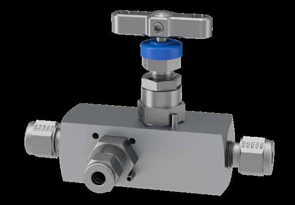
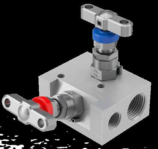
Combining two needle valves into one unitised block, the Parker 2-valve manifolds range is also referred to as Block and Bleed, Isolate and Calibrate or even Isolate and Vent/Drain. These manifolds are used primarily in applications requiring a pressure switch, pressure transmitter or gauge for Static Pressure Measurement. Other forms of sensing technology can be applied, and, in some circumstances, they can also be employed in the measurement of temperature or other process attribute.
In combination with Parker A-LOK® or CPITM compression tube fitting technologies, a superior advantage is gained allowing users to eliminate threaded connections and reduce leak paths, whilst offering superior installation and operational performance.
ReferenceDescription
BLUE RED Isolate/block Drain/vent/test
These 2-valve manifolds are widely used in situations where a static pressure measurement device requires maintenance, offering safe isolation to allow venting/ draining and calibration of the device. They also provide the means for removal and re-installation of an instrument in a live process situation. They are used in every industry in a wide range of applications - everywhere where accurate and secure pressure measurement of steam, air, gas, oil, water or other non-viscous liquids is required.
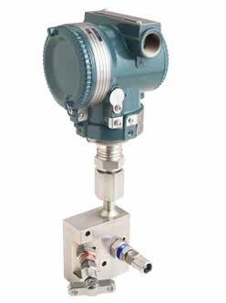
Available as remote (or line mount) they are also available in a direct mounting style for bolting to the face of static pressure transmitters with an array of input connection styles and types. The unique Parker superior advantage in this regard being the ability to create a thread less leak free hook up. Where additional operational security is required, a second isolate valve can be specified, thereby providing an enhanced Double Block and Bleed (DBB) solution.
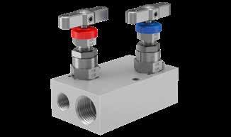
Example shown: 2-valve remote/line mount gauge valve, block and bleed (isolate and vent/drain) with Parker Superior Advantage fully integrated inverted A-LOK® tube fitting connections to inlet/outlet and Parker unique PTFree connectTM tube fitting connection to vent/drain.
We are confident you will find a manifold style, type and connection option to suit your applications, but should you require something different or need assistance to make your selection, please contact your local Parker support.
2-Valve Manifolds - HNL Series
Remote/line mount - long pattern
Combining two needle valves into one unitised block, these slimline long pattern Parker 2-valve manifolds are also referred to as Block and Bleed, Isolate and Calibrate or Isolate and Vent/Drain. These manifolds are ideal for standalone line mounting.
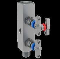
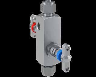
Example shown: 2-valve integral block and bleed manifold with integral A-LOK® connections.
6,0001/2” M1/2” F1/4” F105.0 (4.13)28.6 (1.13)130.2 (5.13) 10,0001/2” M1/2” F1/4” F136.7 (5.38)31.8 (1.25)133.4 (5.25) Pressure (PSI) InletOutletVent
6,0001/2” M1/2” M1/4” F108.5 (4.27)28.6 (1.13)130.2 (5.13)
10,0001/2” M1/2” M1/4” F136.7 (5.38)31.8 (1.25)133.4 (5.25)
InletOutletVent Dimension
Pressure (PSI)
NPTNPTNPT A mm (inch) B mm (inch) C mm (inch)
6,0001/2” F1/2” F1/4” F117.6 (4.63)28.6 (1.13)130.2 (5.13)
10,0001/2” F1/2” F1/4” F117.6 (4.63)31.8 (1.25)133.4 (5.25)
InletOutletVent Dimension
Pressure (PSI)
NPTNPTNPT A mm (inch) B mm (inch) C mm (inch)
6,0001/2” M1/2” F1/4” F136.5 (5.37)31.8 (1.2582.6 (3.25)
10,0001/2” M1/2” F1/4” F136.5 (5.37)31.8 (1.2582.6 (3.25)
6,0001/2” M1/2” M1/4” F136.5 (5.37)31.8 (1.2582.6 (3.25)
10,0001/2” M1/2” M1/4” F136.5 (5.37)31.8 (1.2582.6 (3.25)
Example shown is application is use. HAL*WG 2-valve remote/line mount gauge valve manifold assembled to a Gauge Pressure Transmitter through the integral Swivel Adaptor described on page 31. A Parker Superior Advantage for flexibility of application in use.
6,0001/2” F1/2” M1/4” F136.5 (5.37)31.8 (1.2582.6 (3.25)
10,0001/2” F1/2” M1/4” F136.5 (5.37)31.8 (1.2582.6 (3.25)
Products shown here can be supplied with integral swivel gauge adaptor as shown on page 31.
28 29
1
1Functional colour
cap 2Adjustable gland 3Gland locknut 4Bracket mounting holes 5Bonnet locking pin 1 3 5 4
coded dust
2
HNL*2V - Female x Female threaded - NPT HNL*3DBB - Optional Double Block & Bleed threaded - NPT HNL*2V - Male x Male threaded - NPT HNL*2V - Male x Female threaded - NPT
Instrument Bleed/TestProcess A B C A B C A B C
Dimension
Pressure (PSI) InletOutletVent
NPTNPTNPT A mm (inch) B mm (inch) C mm (inch)
Dimension NPTNPTNPT A mm (inch) B mm (inch) C mm (inch)
A B C
Bleed/TestProcess Instrument
Remote/line mount
Combining two needle valves into one unitised flat block, this Parker 2-valve manifolds range is also referred to as a Block and Bleed, Isolate and Calibrate or even Isolate and Vent/Drain. These manifolds are ideal for robust mounting to bracket work or other structure.
HL*2V - Female x Female threaded -
Example shown: 2-valve manifold with integral A-LOK® connections.
6,0001/2” F1/2” F1/4” F50.8 (2.00)152.4 (6.00)28.6 (1.13) 63.5 (2.50) 10,0001/2” F1/2” F1/4” F50.8 (2.00)152.4 (6.00)31.8 (1.25) 69.8 (2.75)
6,0001/2”
F50.8 (2.00)100.5 (3.96)28.6 (1.13)63.5 (2.50)79.4 (3.13) 10,0001/2” F1/2” F1/4” F63.5 (2.50)114.3 (4.50)31.8 (1.25)69.8 (2.75)82.6 (3.25)
30
- Female x Female threaded - NPT
HL*3DBB - Female threaded - NPT
- Female x Female threaded - NPT Pressure (PSI) InletOutletBleed/test Dimension NPTNPTNPT A mm (inch) B
C
D
HLTF*2V
HLWG*2V - Female threaded - NPT with integral swivel gauge adaptor
HAL*2V
mm (inch)
mm (inch)
mm (inch)
NPT
InletOutletBleed/test Dimension NPTNPTNPT A mm (inch) B mm (inch) C mm (inch) D mm (inch) E mm (inch)
Pressure (PSI)
A B D E A B C D E A D C B A B C D Pressure (PSI) InletOutletBleed/test Dimension NPTNPTNPT A mm (inch) B mm (inch) C mm (inch) D mm (inch) 6,0001/2” F1/2” F1/4” F50.8 (2.00)79.4
10,0001/2” F1/2” F1/4” F55.7 (2.19)82.6 (3.25)31.8 (1.25)88.9 (3.50) Pressure (PSI) InletOutletBleed/test Dimension NPTNPTNPT A mm (inch) B mm (inch) C mm (inch) D mm (inch) E mm (inch) 6,0001/2” F1/2” F1/4” F88.9 (3.50)148.3 (5.84)28.6 (1.13)50.8 (2.00)101.6 (4.00) 10,0001/2” F1/2” F1/4” F88.9 (3.50)148.6 (5.85)31.8 (1.25)57.2 (2.75)107.7 (4.25) Instrument Bleed/Test Process Bleed/Test Process Instrument A B C D Pressure (PSI) InletOutletBleed/test Dimension NPTBSPP*NPT A mm (inch) B mm (inch) C mm (inch) D mm (inch) 6,0001/2” F1/2” F1/4” F58.7 (2.31) 160.3 (6.31) 31.8 (1.25)112.3 (4.42) *In accordance with DIN 16284 - Swivel BSPP 1/2” Female • Swivel adaptor to the outlet is provided through a socket weld, generally conforming to ANSI B16.11. • Weld connection is a “commercial weld”, completed by a qualified welder. Any specific qualification, certification, documentation or additional NDT, will require to be engineered and quoted extra – please consult your local Parker support. • Union nut dimensions generally conform to DIN 16284 as it applies to the union of nipple and nut themselves. • Union nut also conforms generally to DIN EN 837 for the gauge connection itself, as it applies to the union of nipple and nut themselves. 2-Valve Manifolds 31 HL*2V8M8F4F - Male x Female threaded - NPT Pressure (PSI) Inlet OutletBleed/test Dimension NPT NPT NPT A mm (inch) B mm (inch) C mm (inch) D mm (inch) 6,000 1/2” M1/2” F 1/4” F50.8 (2.00)152.4 (6.00)28.6
10,0001/2” M1/2” F 1/4” F50.8 (2.00152.4 (6.00)31.8 (1.25)76.2 (3.00) A B D A B C D Instrument Bleed/Test Process Instrument Bleed/Test Process A B C D A B C D A C D B HLLHV*2V - Female x Female threaded - NPT Instrument Bleed/Test Process Instrument Bleed/Test Process Pressure (PSI) InletOutletBleed/test Dimension NPTNPTNPT A mm (inch) B mm (inch) C mm (inch) D mm (inch) E mm (inch) 6,0001/2” F1/2” F1/4” F50.8 (2.00)101.6 (4.00)79.4 (3.13)28.6 (1.13)63.5 (2.50) Instrument Bleed/Test Process A C D B E A D B E A D E B C C D A B C D E
F1/2” F1/4”
(3.13)28.6 (1.13)85.0 (3.35)
(1.13)73.0 (2.88)
Example 1 (Default): HLS2V
Example 2: HLS2V4RM8RF4F3P
HLS2V
HLS2V4RM8RF4F3P
Example 3: HNLWGS3DBB8M8R4FPOXNC HNLWGS3DBB8M8R4FPOXNC
Example 4: HALS2VIVAM126ATK
Example 5: HNL6MO2VM12ATHLNC
Example 6: HLS3DBBIVZI84FPOX
HALS2VIVM126 ATK
HNL6MO2VM12ATHLNC
HLS3DBBIVZI84FPOX
Example 7: HL6MO3DBBIVAM12PFCAM6NC HL6MO3DBBIVAM12PFCAM6NC
Series
HNL Straight barstock gauge valves, long pattern
HNLWG Straight barstock gauge valves, long pattern with Integral Swivel Gauge connection1
HL Flat barstock gauge valves, short pattern
HLWG Flat barstock gauge valves, short pattern with Integral Swivel Gauge connection1
HAL Angled barstock gauge valves, short pattern
HALWG Angled barstock gauge valves, short pattern with Integral Swivel Gauge connection1
HLTF Flat barstock gauge valves with valves on top face
HLLHV Flat barstock gauge valves, short pattern with valves at 90 degree and left hand orientation
1 Available as standard with 1/2” BSPP 8R); 1/4” BSPP 4R by special request. Available only in 316SS. Consult your local Parker support for other potential material options.
2 This material selection down-rates manifold.
Application Configuration
2V 2-valve, block and bleed/vent/drain, isolate and calibrate
3DBB 3-valve, double isolate and bleed/vent/drain, block-bleed-block4
3DBB1 3-valve, double isolate and bleed/vent/drain, block-block-bleed4 Available on HL and HNL series only.
Connections - Standard Options
Inlet Outlet Vent
* 1/2” NPT Fem.1/2” NPT Fem.1/4” NPT Fem.
4N 1/4” NPT Fem.1/4” NPT Fem.1/4” NPT Fem.
4K 1/4” NPT Fem.1/4” NPT Fem.1/4” NPT Fem.
4R 1/4” BSPP Fem.1/4” BSPP Fem.1/4” BSPP Fem.
8K 1/4” BSPT Fem.1/4” BSPT Fem.1/4” BSPT Fem.
8R 1/2” BSPP Fem.1/2” BSPP Fem.1/4” BSPP Fem.
4M4F4F 1/4” NPT Male1/4” NPT Fem.1/4” NPT Fem.
8M8F4F 1/2” NPT Male1/2” NPT Fem.1/4” NPT Fem.
12M8F4F 3/4” NPT Male1/2” NPT Fem.1/4” NPT Fem.
4A 1/4” A-LOK5 1/4” A-LOK5 1/4” NPT Fem.
6A 3/8” A-LOK5 3/8” A-LOK5 1/4” NPT Fem.
8A 1/2” A-LOK
•
2-valve block & bleed/islolate & calibrate/vent/drain, short pattern flat barstock manifold, manufactured from 316 Austenitic Stainless Steel material, having 1/2” NPT Fem. connection to both inlet & outlet and a 1/4” NPT fem. bleed/vent/drain connection. Gland packing is PTFE.
2-valve block & bleed/islolate & calibrate/vent/drain, long pattern flat barstock manifold, manufactured from 316 Austenitic Stainless Steel material, having 1/4” BSPP Male connection to inlet & 1/2” BSPP Fem. outlet with 1/4” NPT Fem. vent/drain connection. Gland packing is Graphite and a 1/4” NPT blanking plug is supplied.
3-valve block-bleed-block/double isolate & bleed/vent/drain, long pattern barstock manifold, manufactured from 316 Aust.St.St., with 1/2” NPT male inlet connection, 1/2” BSPP fem. outlet connection via integral welded swivel and 1/4” NPT fem. vent/drain/bleed. A 1/4” NPT blanking plug is supplied. Suitable for oxygen service and complies to NACE.
2-valve angle head block & bleed/isolate & calibrate/vent/drain, short pattern flat barstock manifold, 316 Aus.St.St. material with Parker Superior Advantage 12mm inverted tube con. to inlet and outlet. The bleed/vent/drain is also an inverted A-LOK tube con. suitable for 6mm tube. Gland packing is PTFE. Anti-Tamper operation and a single key.
2-valve block & bleed, long pattern manifold, manufactured from 6MO super austenitic stainless steel material with Parker A-LOK 12mm CPI integral tube connections to inlet and outlet and 6mm CPI PTFree connect male union to bleed/vent/drain. Manifold is also fitted with locking T bar handle operation and is compliant to NACE.
3-valve block-bleed-block/double isolate & calibrate vent/drain, flat barstock manifold manufactured from 316 Austenitic Stainless Steel material having Parker Superior 1/2” Inverted integral CPI tube connections and a 1/4” NPT fem. vent/drain/bleed. Gland packing is PTFE. A 1/4” NPT blanking plug is supplied. Suitable for oxygen service.
3-valve block-bleed-block/double isolate & calibrate vent/drain, flat barstock manifold manufactured from 6MO Super Austenitic Stainless Steel material having Parker Superior Advantage 12mm inverted integral A-LOK tube connections to inlet and outlet with 6mm integral PTFree male union A-LOK tube connection to vent/drain/bleed. Gland packing is PTFE and the manifold complies to NACE.
14 Not required when Firesafe design option FS) selected.
15 Not available for PCTFE Soft Tip (9 or Oxygen use OX).
16 6mm bore seat and other flow passages not available on all selections. Please consult your local Parker support.
17 3,000 PSI/207 BAR only. See main catalogue page.
18 Plugs supplied loose in a packing box. See main catalogue page.
19 These options can be specified to independent valves: Add to specify specify assembly to Isolate valves.
Add V to specify specify assembly to Vents/Drains/Bleeds.
Examples:
• AT = Anti-Tamper to Isolate valve.
• HWV = Handwheel to Vents/Drains/Bleeds.
20 Anti-Tamper operation and no Key.
21 Anti-Tamper operation and one Key supplied per manifold.
22 Specify quantity required as separate line item.
IMPORTANT NOTES:
optimum results in integral
connections on manifolds, the use of Parker pre-assembly tooling is highly recommended. For inverted style integral
connections the use of Parker pre-assembly tooling is mandatory.
• Not all options/combinations are available in each single product model type.
• We reserve the right to review/revise this part number structure at any time. If necessary, we can refuse and/or recommend the most suitable alternative part number(s). We may also apply MOQ rules.
• Should your part number selection exceed 25 characters in length when completed, then it is likely to be incorrect, please consult your local Parker representation for assistance.
• If in any doubt, please consult your local Parker representation.
Ordering information 2-Valve Manifolds - Remote/Line Mount 33 Materials S 316/316L Stainless Steel HC Hastelloy C276 6MO 6MO Sup. Aust. St.Steel T Titanium Gr. 22 M Monel 4002 825 Inconel 825 D1 Duplex 22 Cr. Steel 625 Inconel 625 D2 Super Duplex 25 Cr. Steel C Carbon Steel3 3 For Carbon Steel consult your local Parker representation. 5 Available on HNL series only. For CPITM (single ferrule tube fitting) connection change A to Z 1/4” NPT Fem. is default standard, some model types may be available with other connections.
5 1/2” A-LOK5 1/4” NPT Fem.
6mm A-LOK5 6mm A-LOK5 1/4” NPT Fem.
10mm A-LOK5 10mm A-LOK5 1/4” NPT Fem.
12mm A-LOK5 12mm A-LOK5 1/4” NPT Fem. Default standard manifolds require no additonal designators. Example: 1/2” NPT Fem. inlet & 1/2” NPT Fem. outlet & 1/4”NPT Fem. vent = HL*2V (as example above). As connection choices vary, all connections must be designated. Examples: • 1/4” NPT Male 4M inlet, 1/2” NPT Fem. (8F outlet, 1/4” NPT Fem. vent (4F) = 4M8F4F • 1/2”BSPP Fem. 8RF) inlet & 1/2”BSPP Fem. 8RF outlet & 1/4”NPT Fem. vent 4F = 8RF8RF4F • 1/2”BSPP Fem. 8RF) inlet & 1/2”BSPP Fem. 8RF outlet & 1/4”BSPT Fem. (4KF vent = 8RF8RF4KF Insert size designator. # Insert specification K/R/RD). * Default connection, no designator required 11 Examples: • 10mm A-LOK inverted inlet/outlet & 1/4” NPT Fem. vent/drain = IVAM104F • 10mm CPI inverted inlet/outlet & 1/4” NPT Fem. vent/drain = IVZM104F 12 Examples: • 10mm A-LOK tube stub con. inlet/outlet & 1/4” NPT Fem. vent/drain = PFAM104F • 3/8” CPI male union con. inlet/outlet & 1/4”NPT Fem. vent/drain = PFCZI64F Butt Weld and Male Socket Weld - Pipe8 Type Size Schedule (Thickness) Extension BW Butt Weld9 MSW Male Socket Weld10 4 1/4” NB 6 3/8” NB 8 1/2” NB 12 3/4” NB * Sch.80 A Sch.160 B Sch.XXS * Default C 75mm D 100mm 8 Available on HNL series only. 7 As standard, valves with Female Socket Weld connections will be of the same length as per the equivalent NPT pipe threaded variants. * No designator required. 9 As standard, valves with butt weld pipe connections will be of the same length as per the equivalent male NPT pipe threaded variants. Extended body dimensions
M6A
M10A
M12A
are also offered - see tables and main catalogue.
10 As standard, valves with Male Socket Weld conn. will have 1/2” (13mm) added to overall length (per connection) when compared to equivalent threaded valve. Extended body dimensions are also offered - see tables and main catalogue. Example: 3/4” NB male socket weld conn. with Sch.XXS wall pipe and 100mm body extension = MSW12BD 13 1/4” NPT Fem. is default standard for bleed/vent/drain, some model types may be available with other connections
Inverted Connection and PTFree connectTM Type Fitting Unit Inlet/Outlet Bleed/Vent/ Drain IV Inverted Connection Tube OD11 PF PTFree connect tube stub12 PFC PTFree connect male union12 A A-LOK Z CPI M Metric 6 6mm 10 10mm 12 12mm 4F 1/4” NPT13 I Imperial 4 1/4” 6 3/8” 8 1/2” Other Connection Options6 *F Fem. NPT connection. Utilise for non-default selections *M Male NPT connection. Utilise for non-default selections *#F Fem. connection. Utilise when connections and specifications vary *#M Male connection. Utilise when connections and specifications vary K BSPT BS21, ISO7/1 - British Standard Taper Pipe thread R BSPP BS2779 - British Standard Parallel Pipe thre RD DIN 16284/16288/EN837 BSPP gauge connection type SW* ASME B16.11, EN12760 Female Socket Weld7
OPTIONS High Pressure - 10,000 PSI (689 bar) option HP High Pressure Gland Packing Options 3 Graphite14 FS Firesafe design15 Seating Options - Needle Valves only 6S 6mm bore seat16 RT Regulating/Metering Tip ST Stellite Tip 9 PCTFE Soft Tip17 PK PEEK Soft Tip Plug/Bleed Valve Options18 P Blank Plug BV Bleed Valve/Plug Operator Options19 HW Handwheel for all valves LHW Handwheel Locking for all valves THL T Bar Locking for all valves AT Anti-Tamper for all valves20 ATK Anti-Tamper for all valves with Key21 ATHKEY Anti-Tamper Key22 Mounting Options BK Assembled with Carbon Steel bracketry & bolts BKS Assembled with Stainless Steel bracketry & bolts Other Options OX Cleaned & lubricated for Oxygen use NC NACE MR-01-75 Compliant
For
tube
tube
Brackets for remote/line mount manifolds and gauge valves


It is essential to fully support
measurement tubing lines, manifolds and instruments. For this reason, all Parker manifolds are designed to accommodate bracket mounting and support. A full range of
be
3 and 5-Valve Manifolds - H Series
Introduction
this Parker 3 and 5-valve manifolds range is primarily used in applications requiring Differential Pressure Transmitters, Gauges and/or Chart Recorders mainly for the purpose of flow measurement. In some circumstances, differential pressure measurement will also be used in other applications, such as level or filtration.
Combining
fully assembled to the
or supplied separately for on-site installation. Available in either all carbon or all stainless steel, they are specifically matched to Parker manifolds to ensure the clearance


Brackets
Bracket kits include U bolts with nuts and washers.
Parker is also able to offer all other items necessary to complete your installations, including the 2”NB pipe stands, tubing clamps, cable/tube trays, populated enclosure solutions and much more. For further information please contact your local Parker support.
In combination with Parker A-LOK® or CPITM compression tube fittings and PTFree connectTM technologies, a superior advantage is gained allowing users to eliminate threaded connections and reduce leak paths, whilst offering superior installation and operational performance.
HOLES
MTG.
4-OFF
Ø8.5 [Ø0.33"]
HOLES 69.5 [2.74]
1 5
instrument mount bolt holes
heat code traceability
T-bar operator
29.0 [1.14] 69.5 [2.74] 90.0 [3.54] 69.5 [2.74] 90.0 [3.54]
29.0 (1.14) 90.0 (3.54) 69.5 (2.74) 69.5 (2.74) 90.0 (3.54)
inlet connection
4-OFF Ø8.5 [Ø0.33"] MTG. HOLES
4-OFF Ø8.5 (Ø0.33) MTG. HOLES 29.0 [1.14] 69.5 [2.74] 90.0 [3.54] 69.5 [2.74] 90.0 [3.54]
4-OFF Ø8.5 [Ø0.33"] MTG. HOLES
These manifolds are widely used in situations where a differential pressure measurement device requires maintenance, offering safe isolation to allow venting/ draining and calibration of that device. They also provide the means for removal and re-installation of an instrument in a live process situation. They are used in every industry in a wide range of applications - everywhere where accurate and secure pressure measurement of steam, air, gas, oil, water or other non-viscous liquids is required.

We are confident you will find a manifold style, type and connection option to suit your applications, but should you require something different or need assistance to make your selection, please contact your local Parker support.
61.5 2.42]
4-OFF Ø8.5 (Ø0.33) MTG. HOLES 34

61.5 (2.42)
46.3 [1.82]
85.0 (3.35) 46.3 (1.82) 69.5 (2.74)
85.0 [3.35] [2.74]
mounting kits
Item Part Number Suitable for Manifold Type Bracket material: Carbon Steel Bracket material: Stainless Steel Bracket with M8 ‘U’ Bolt and manifold Bolt Kit Nuts and washers: M5 x 45 Bolt (2-OFF) BKT1CSB1BKT1SSB1 HL*2V HL*2V8M8F4F HAL*2V HLLHV*2V How to order: Item Part Number Suitable for Manifold Type Bracket material: Carbon Steel Bracket material: Stainless Steel Bracket with M8 ‘U’ Bolts and manifold Bolt Kit (Nuts and washers: M5 x 45 Bolt (2-OFF) BKT2CSB1 BKT2SSB1 HAL*2VHP HLTF*2V Bracket with M8 ‘U’ Bolts and manifold Bolt Kit (Nuts and washers: M10 x 12 Bolt (2-OFF) BKT2CSB2 BKT2SSB2 HL*3DBB HL*3DBB1 How to order: Mounting Brackets 35 Brackets for 2-valve remote mount manifolds and 3-valve DBB manifolds - BKT2 Image shown: Part No.: HLS2VBKImage shown: Part No.: BKT1SSB1 ‘U’ bolt with nuts and washers for 2” NB standpipe Image shown: Part No.: HLS3DBBBK Image shown: Part No.: BKT2SSB2
impulse/pressure
bracket
can
supplied
manifolds,
bonnet assemblies
block,
three or five
into one
4 ReferenceDescription 1Transmitter
2Material
3Ergonomic
4Process
5Transmitter
BLUE RED
Available as remote (or line mount) they are also available in a direct mounting style for bolting directly to the face of Differential Pressure Transmitters with an array of input connection styles and types. The unique Parker superior advantage in this regard is being the ability to create a threadless leak-free hook up. Where additional operational security or functionality is required, a number of differing flow path configurations and additional ports are available to allow purging upstream or downstream of the isolation valves. Isolate/block Drain/vent/test Equalise
equalise valve
GREEN
3 2
Example shown: 3-valve direct mount manifold with NPT connections and additional test/purge ports.
needed to efficiently operate all handles and are also designed to offer maximum rigidity and support in horizontal or vertical orientations on panels, walls or 2” NB pipe stands.
for 2-valve remote mount manifolds - BKT1 29.0 [1.14] 47.0 [1.85] 90.0 [3.54] 4-OFF Ø8.5 [Ø0.33"]
69.5 [2.74]
29.0 [1.14] 47.0 [1.85] 90.0 [3.54]
MTG.
29.0 (1.14) 47.0 (1.85) 69.5 (2.74) 90.0 (3.54)
Remote/line mount
These 3-valve remote mount manifolds combine three needle valves into one unitised block to create Isolation for the instrument impulse lines and an Equalisation feature to assist in installation and maintenance of the remotely connected instrument(s). They are truly flexible having a multitude of available connection options.
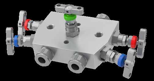
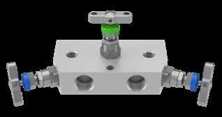
Example shown: 3-valve remote/line mount manifold featuring the Parker A-LOK® Superior Advantage inverted integral tube fitting connections.
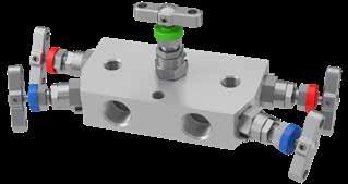
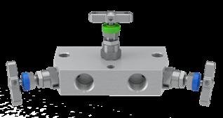
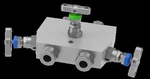
5-Valve Manifolds - H Series
Remote/line mount
These 5-valve remote mount manifolds combine five needle valves into one unitised block to create Isolation for the instrument impulse lines and an Equalisation feature to assist in installation and maintenance of the remotely connected instrument(s). They also incorporate vent/drain or calibration valves and ports. These manfolds are truly flexible, having a multitude of available connection options and are suitable for use in many applications including those utilising Differential Pressure Gauges.
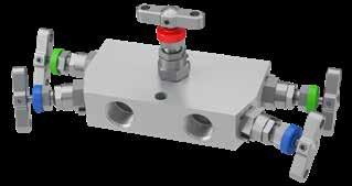
Example shown: 5-valve remote/line mount manifold featuring the Parker A-LOK® Superior Advantage Inverted integral tube fitting connections for the impulse line and NPT ported connections for the vent/ drains.
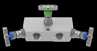
HL*5M - Female x Female threaded - NPT
6,0001/2” NPT1/2” NPT54.0 (2.125)120.0 (4.72)220.0 (8.66)28.6 (1.13)79.4 (3.13)63.5 (2.50) 10,0001/2” NPT1/2” NPT54.0 (2.125)132.0 (5.20)232.0 (9.14)31.8 (1.25)82.6 (3.25)63.5 (2.50)
Pressure PSI InletOutlet Bleed /test Dimension A mm (inch) B mm (inch) C mm (inch) D mm (inch) E mm (inch) F mm (inch) 6,0001/2” NPT1/2” NPT1/4” NPT54.0 (2.125)120.0 (4.72)221.6 (8.72)28.6 (1.13)79.4 (3.13)63.6 (2.50) 10,0001/2” NPT1/2” NPT1/4” NPT54.0 (2.125)132.0 (5.20)233.6 (9.20)31.8 ((1.25)82.6 (3.25)76.2 (3.00)
HL*5MCT - Female x Female threaded - NPT
(2.125)120.0 (4.72)220.0 (8.66)28.6 (1.13)79.4 (3.13)63.5 (2.50)
(2.125)120.0 (4.72)221.6 (8.72)28.6 (1.13)79.4 (3.13)63.6 (2.50)
d p
PSI InletOutlet Dimension A mm (inch) B mm (inch) C mm (inch) D mm (inch) E mm (inch) F mm (inch)
HL*3M - Female x Female threaded - NPT
Pressure
A B D C A B C D E F 36 37
3-Valve Manifolds - H Series
d p A B D C A B C D E F Pressure PSI InletOutlet Drain/Bleed/ Test Dimension A mm (inch) B mm (inch) C mm (inch) D mm (inch) E mm (inch) F mm (inch)
NPT1/2” NPT1/4” NPT54.0
d p E F A B C D E F Pressure PSI InletOutlet Drain/Bleed/ Test Dimension A mm (inch) B mm (inch) C mm (inch) D mm (inch) E mm (inch) F mm (inch) 6,0001/2” NPT1/2” NPT1/4” NPT54.0 (2.125)120.0 (4.72)220.0 (8.66)28.6 (1.13)79.4 (3.13)63.5 (2.50) HL*3MUPP - Female x Female
HL*3MDTP - Female x Female threaded - NPT with downstream test ports
6,0001/2”
threaded - NPT with upstream purge ports
Test/ drain ProcessTest/ drain ProcessDrainProcess
E B A C D E F
F F B A C D E F
Pressure PSI InletOutlet Bleed /test Dimension A mm (inch) B mm (inch) C mm (inch) D mm (inch) E mm (inch) F mm (inch) 6,0001/2” NPT1/2” NPT1/4” NPT54.0
Example 1 (Default): HLS5M
Example 2: HL6MO3M4NHPPATEBKSNC
Example 3: HL6MO3MUPPPFAI44PKPOX
Example 4: HLS5MSW83PATKVBKNC
Example 5: HLS5MCTPFCAM126ATKE
Example 6: HL6MO5MIVAM12PFCAM6
HLS5M
HL6MO3M4NHPPATEBKSNC
HL6MO3MUPPPFAI44PKPOX
HLS5MSW83PATKVBKNC
HLS5MCTPFCAM126ATKE
HL6MO5MIVAM12PFCAM6
5-valve remote mount, thread to thread 6,000 PSI manifold, manufactured from 316 Stainless Steel material having 1/2” NPT Fem. connections to inlets and outlets with 1/4” NPT Fem. connections to vents. Gland packing is PTFE.
3-valve remote mount, thread to thread 10,000 PSI manifold, manufactured from 6MO material having 1/4” NPT Fem. connections to inlets and outlets. Gland packing is PTFE. Manifold has Anti-tamper operation to the equalise valve, is fitted to a stainless steel mounting bracket assembly and complies to NACE.
3-valve remote mount, tube to tube manifold, manufactured from 6MO material having 1/4” A-LOK PTFree tube stub con. to inlets and outlets. There are 2 additional 1/4” NPT Fem. upstream test ports - 1/4” NPT blanking plugs supplied. Gland packing is PTFE. Valves are fitted with PEEK soft tip stems; manifold is cleaned suitable for oxygen service.
5-valve remote mount, 6,000 PSI manifold manufactured from 316 SS material having 1/2” NB Fem. socket weld con. to inlets and outlets with 1/4” NPT Fem. vent ports. Gland packing is Graphite. Manifold also includes Anti-tamper operation to the vent valves, is fitted with a Carbon S mounting bracket assembly and complies to NACE. One Antitamper key and two 1/4” NPT blanking plugs are also supplied.
5-valve remote mount manifold manufactured from 316 SS having Parker Superior advantage 12mm A-LOK PTFree male union con. to inlets and outlets with 6mm PTFree male union con. to the vents/drains/bleeds. Gland packing is PTFE. Manifold is fitted with Anti-tamper operation to the equalise valve and suppled with one Anti-tamper key.
5-valve remote mount, tube to tube manifold, manufactured from 6MO Aust. Stainless Steel material having Parker Superior Advantage 12mm A-LOK inverted tube connections to inlets and outlets with 6mm A-LOK PTFree male union connections to the vents. Gland packing is PTFE.
Not required when Firesafe design option (FS) selected. Not available for PCTFE Soft Tip 9) or Oxygen use (OX).
6mm bore seat and other flow passages not available on all selections. Please consult your local Parker support.
10 3,000 PSI/207 BAR only. See main catalogue page.
Application Configuration
3M 3-valve, isolate and equalise
3MDTP 3-valve, isolate and equalise with downstream vent/drain/bleed/test ports
3MUPP 3-valve, isolate and equalise with upstream purge ports
5M 5-valve, isolate, equalise with vent/test/bleed
5MCT 5-valve, isolate, equalise with vent/test/bleed suitable for Custody Transfer applications
Connections - Standard Options
Inlet Outlet Vent
* 1/2” NPT Fem.1/2” NPT Fem.1/4” NPT Fem.
4N 1/4” NPT Fem.1/4” NPT Fem.1/4” NPT Fem.
4K 1/4” BSPT Fem.1/4” BSPT Fem.1/4” BSPT Fem.
4R 1/4” BSPP Fem.1/4” BSPP Fem.1/4” BSPP Fem.
8K 1/2” BSPT Fem.1/2” BSPT Fem.1/4” BSPT Fem.
8R 1/2” BSPP Fem.1/2” BSPP Fem.1/4” BSPP Fem.
SW8 1/2” NB Fem. SW3 1/2” NB Fem. SW3 1/4” NPT Fem.
Default standard manifolds require no additonal designators. Example: 1/2” NPT Fem. inlet & 1/2” NPT Fem. outlet & 1/4”NPT Fem. vent = HL*5M (as above)
As connection choices vary, all connections must be designated. Examples:
1/2”BSPP
11 Plugs supplied loose in a packing box. See main catalogue page.
12 These options can be specified to independent valves: Add E to specify assembly to Equalise valve only.
Add I to specify assembly to Isolate valves.
Add V to specify assembly to Vents/Drains/Bleeds.
Examples:
• HWV = Handwheel to Vents/Drains/Bleeds.
• ATE = Anti-Tamper to Equalise valve.
13 Anti-Tamper operation and no Key.
14 Anti-Tamper operation and one Key supplied per manifold.
15 Specify quantity required as separate line item.
IMPORTANT NOTES:
• For optimum results in integral tube connections on manifolds, the use of Parker pre-assembly tooling is highly recommended. For inverted style integral tube connections the use of Parker pre-assembly tooling is mandatory.
• Not all options/combinations are available in each single product model type.
• We reserve the right to review/revise this part number structure at any time. If necessary, we can refuse and/or recommend the most suitable alternative part number(s). We may also apply MOQ rules.
• Should your part number selection exceed 25 characters in length when completed, then it is likely to be incorrect, please consult your local Parker representation for assistance.
• If in any doubt, please consult your local Parker representation.
38 Ordering information 3 and 5-Valve Manifolds - Remote/Line Mount 39 Materials S 316/316L Stainless Steel HC Hastelloy C276 6MO 6MO Sup. Aust. St.Steel T Titanium Gr. 21 M Monel 400 825 Inconel 825 D1 Duplex 22 Cr. Steel 625 Inconel 625 D2 Super Duplex 25 Cr. Steel C Carbon Steel2
Optional Connections Type Fitting Unit Inlet/Outlet Bleed/Vent/ Drain IV Inverted Connection Tube OD4 PF PTFree connect tube stub5 PFC PTFree connect male union5 A A-LOK Z CPI M Metric 6 6mm 10 10mm 12 12mm 4F 1/4” NPT6 Imperial 4 1/4” 6 3/8” 8 1/2” 1 This material selection down-rates manifold. 2 For Carbon Steel consult your local Parker representation. Examples: • 10mm A-LOK tube stub con. inlet/outlet & 1/4” NPT Fem. vent/drain = PFAM104F • 3/8” CPI male union con. inlet/outlet & 1/4”NPT Fem. vent/drain = PFCZI64F • 12mm A-LOK male union con. inlet/outlet & 6mm A-LOK vent/drain = PFCAM126 4 Examples: • 10mm A-LOK inverted inlet/outlet & 1/4” NPT Fem. vent/drain = IVAM104F • 10mm CPI inverted inlet/outlet & 1/4” NPT Fem. vent/drain = IVZM104F • 12mm A-LOK inverted inlet/outet & 6mm vent/drain = IVAM126 • 1/2” A-LOK inverted inlet/outlet & 1/4” vent/drain = IVAI84 6 1/4” NPT Fem. is default standard for bleed/vent/drain, some model types may be available with other connections. Series HL Flat barstock remote/line mount/pipe to pipe/thread to thread manifolds OPTIONS High Pressure - 10,000 PSI (689 bar) option HP High Pressure Gland Packing Options 3 Graphite FS Firesafe design8 Seating Options - Needle Valves only 6S 6mm bore seat9 RT Regulating/Metering Tip ST Stellite Tip 9 PCTFE Soft Tip10 PK PEEK Soft Tip Plug/Bleed Valve Options11 P Blank Plug BV Bleed Valve/Plug PBV Blank Plug and Bleed Valve/Plug Operator Options12 HW Handwheel for all valves LHW Handwheel Locking for all valves THL T Bar Locking for all valves AT Anti-Tamper for all valves13 ATK Anti-Tamper for
valves
Key14 ATHKEY Anti-Tamper Key15 Mounting Options BK Assembled with Carbon Steel bracketry & bolts BKS Assembled with Stainless Steel bracketry & bolts Other Options OX Cleaned & lubricated for Oxygen use NC NACE MR-01-75 Compliant
•
Fem. inlet & 1/2”BSPP Fem. outlet & 1/4”NPT Fem. vent = 8R4F • 1/2”BSPP Fem. inlet & 1/2”BSPP Fem. outlet & 1/4”BSPT Fem. vent = 8R4K * Default connection, no designator required 3 As standard, valves with Female Socket Weld connections will be of the same length as per the equivalent NPT pipe threaded variants.
all
with
Direct mount
Combining two needle valves into one unitised block, this 2-valve manifolds range is also referred to as a Block and Bleed, Isolate and Calibrate or even Isolate and Vent/Drain. These manifolds are specifically designed for direct connection to absolute/gauge pressure transmitters, having bolted interface conforming to DIN IEC61518 Type B as standard, and type A available by request. With additional mounting holes and a wide range of bracketry, these manifolds can also be utilised as support for the instrument within any installation.
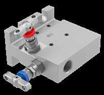

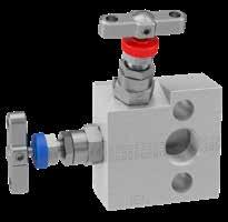
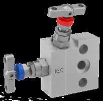
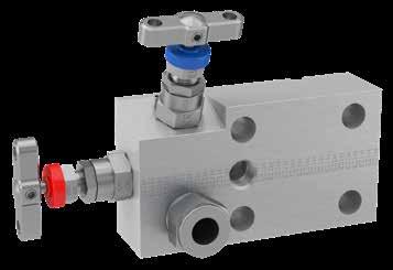
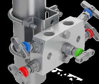
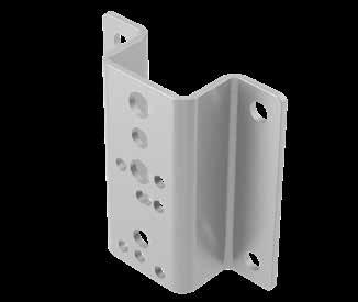
Example shown: 2-valve manifold with inverted integral A-LOK® connections.
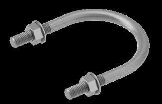
HD*2M- Female threaded - NPT x Flanged 114.3 (4.50”)
HD*2MFF - Flanged x Flanged (straight through bolted flange)

Pressure (PSI)
63.5 (2.50”) 28.6 (1.13”) 114.3 (4.50”)
63.5 (2.50”) 28.6 (1.13”)
B C D 40
for remote/line mount manifolds and gauge valves Mounting Brackets 41 How to order: Brackets for 3 and 5-valve remote mount manifolds - BKT2
Universal manifold mounting bracket, suitable for all remote mount manifolds
enabling
and
obstruction
or base mounted Item Part Number Suitable for Manifold Type Bracket material: Carbon Steel Bracket material: Stainless Steel Bracket with M8 ‘U’ Bolt and manifold Bolt Kit (Nuts and washers: M8 x 45 Bolt (2-OFF) BKT2CSB5BKT2SSB5 HL*3M HL*3MDTP HL*5M HL*5MCT HL*5MHP ‘U’ bolt with nuts and washers for 2” NB standpipe Image shown: Part No.: HLS5MBKImage shown: Part No.: BKT2SSB5
Brackets
•
• Allows 90 degree positioning
total installation flexibility
prevents handle
• Can be wall, standpipe
Instrument
Bleed/TestProcess
Bleed /test Dimension A mm
Pressure (PSI) InletOutlet Bleed /test Dimension A mm
B
C mm
D
E
NPT
2-Valve Manifolds - H Series HEH*2 - Flanged x Flanged HET*2 - Female threaded - NPT x Flanged Pressure (PSI) InletOutlet Bleed /test Dimension A mm (inch) B mm (inch) C mm (inch) D mm (inch) E mm (inch) F mm (inch) 6,000FlangedFlanged 1/4” NPT 98.5 (3.88) 149.3 (5.88) 31.8 (1.25) 62.0 (2.44) 96.4 (3.80) 95.8 (3.77) A D E B C A B C D E B C A B C D E 29.0 [1.14] 69.5 [2.74] 90.0 [3.54] 69.5 [2.74] 90.0 [3.54] 4-OFF Ø8.5 [Ø0.33"] MTG. HOLES 29.0 [1.14] 69.5 [2.74] 90.0 [3.54] 69.5 [2.74] 90.0 [3.54] 4-OFF Ø8.5 [Ø0.33"] MTG. HOLES 29.0 (1.14) 90.0 (3.54) 69.5 (2.74) 69.5 (2.74) 90.0 (3.54)
D E B A B C D E F B C D A B C D E F Pressure (PSI) InletOutlet Bleed /test Dimension A mm (inch) B mm (inch) C mm (inch) D mm (inch) E mm (inch) F mm (inch) 6,000 1/2” NPT Flanged 1/4” NPT 98.5 (3.88) 149.3 (5.88) 31.8 (1.25) 62.0 (2.44) 101.6 (4.00) 80.7 (3.18) Bracket kits include
bolts with nuts and
Ø(2.42)
InletOutlet
(inch) B mm (inch) C mm (inch) D mm (inch) E mm (inch) 6,000FlangedFlanged 1/4” NPT 63.5 (2.50) 114.3 (4.50) 28.6 (1.13) 63.5 (2.50) 107.6 (4.24)
(inch)
mm (inch)
(inch)
mm (inch)
mm (inch) 6,000 1/2”
Flanged 1/4” NPT 63.5 (2.50) 114.3 (4.50) 28.6 (1.13) 63.5 (2.50) 107.6 (4.24)
4-OFF Ø8.5 (Ø0.33) MTG. HOLES
U
washers. 85.0 [3.35] 69.5 [2.74] 46.3 [1.82]
61.5 2.42] 85.0 (3.35) 46.3 (1.82) 69.5 (2.74) 61.5
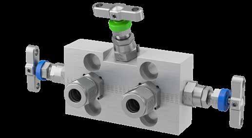
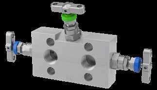
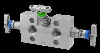
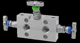
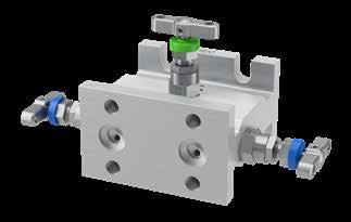
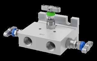
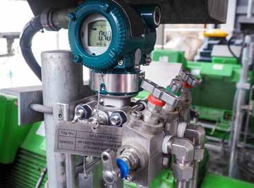
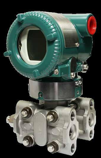
43 42
- Female threaded
NPT x
3-Valve Manifolds - H Series HD*3MA - Female threaded - NPT x Flanged Inlet Outlet Dimension A mm (inch) B mm (inch) C mm (inch) D mm (inch) E mm (inch) 1/2” NPT Flanged110.0 (4.33)211.6 (8.33)28.6 (1.13)63.5 (2.50)107.6 (4.24) Inlet Outlet Dimension A mm (inch) B mm (inch) C mm (inch) D mm (inch) E mm (inch) 1/2” NPT Flanged110.0 (4.33)211.6 (8.33)28.6 (1.13)63.5 (2.50)91.0 (3.58) HD*3MDTP - Female threaded - NPT x Flanged with downstream test ports Inlet Outlet Dimension A mm (inch) B mm (inch) C mm (inch) D mm (inch) E mm (inch) F mm (inch) 1/2” NPTFor 305133.0 (1.30)110.0 (4.33)211.6 (8.33)28.6 (1.13)63.5 (2.50)107.6 (4.24) B E A D C A B C D E D E A B C D E A B A B C D E HET*3 - Female threaded - NPT x Flanged Inlet Outlet Dimension A mm (inch) B mm (inch) C mm (inch) D mm (inch) E mm (inch) F mm (inch) 1/2” NPT Flanged98.5 (3.88”)200.1 (7.88”)31.8 (1.25”)62.0 (2.44”)101.6 (4.00”)82.6 (3.25”) A B C D E F A B F A B C D E F d p Inlet Outlet Dimension A mm (inch) B mm (inch) C mm (inch) D mm (inch) E mm (inch) F mm (inch) Flanged Flanged98.5 (3.88”)200.1 (7.88”)31.8 (1.25”)62.0 (2.44”)96.4 (3.80”)97.7 (3.85”) d p Recognising and understanding the direct mount transmitters* * Not Emerson CoplanarTM types – For CoplanarTM please see page 55. Connection centres are 2 1/8” (54mm) Bolt hole centres are 2 1/8” (54mm) x 1 5/8” (41mm) Manifolds mount to this IEC compliant interface • Pressure applications utilise 2-valve manifolds bolted with 2 bolts • Differential applications utilise 3 or 5-valve manifolds bolted with 4 bolts 7/16” UNF mounting holes Typical installation Instrument d p Process HEH*3 - Flanged x Flanged Process Process Instrument d p Process Instrument Instrument d p Process Instrument
Direct mount These 3-valve direct mount to differential pressure transmitter manifolds combine three needle valves into one unitised block to create Isolation for the instrument impulse lines and an Equalisation feature to assist in installation and maintenance. They comply fully with IEC 61518 and have a multitude of advantageous connection & application options. HD*3M
-
Flanged Example shown: 3-valve manifold with PTFree connectTM connection.
individual
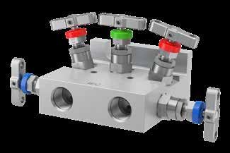
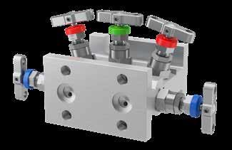
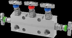
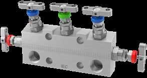
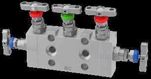
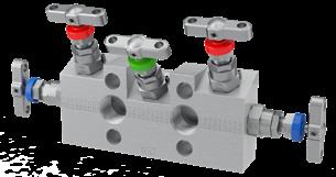
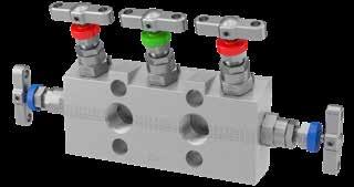
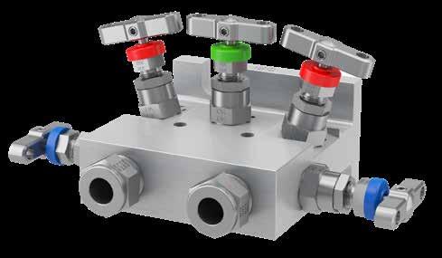
44 45
mount These
5-Valve Manifolds - H Series HD*5M - Female threaded - NPT x Flanged HD*5MA - Female threaded - NPT x Flanged HD*5MFF - Flanged x Flanged (straight through bolted flange) Test/ drain ProcessTest/ drain InletOutletBleed/test Dimension A mm (inch) B mm (inch) C mm (inch) D mm (inch) E mm (inch) 1/2” NPTFlanged1/4” NPT138.0 (5.43)239.6 (9.43)63.5 (2.50)28.6 (1.13)107.6 (4.24) InletOutletBleed/test Dimension A mm (inch) B mm (inch) C mm (inch) D mm (inch) E mm (inch) FlangedFlanged1/4” NPT138.0 (5.43)239.6 (9.43)63.5 (2.50)28.6 (1.13)107.6 (4.24) Test/ drain ProcessTest/ drain InletOutletBleed/test Dimension A mm (inch) B mm (inch) C mm (inch) D mm (inch) E mm (inch) 1/2” NPTFlanged1/4” NPT138.0 (5.43)239.6 (9.43)63.5 (2.50)28.6 (1.13)104.7 (4.12) Test/ drain ProcessTest/ drain A B C D A B D C E Example shown: 5-valve extruded direct mount manifold with Parker Superior Advantage fully integrated inverted A-LOK® tube fitting connections. C A B D C E D A B D C E HD*5CT - Female threaded - NPT x Flanged Test/ drain ProcessTest/ drain InletOutletBleed/test Dimension A mm (inch) B mm (inch) C mm (inch) D mm (inch) E mm (inch) 1/2” NPTFlanged1/4” NPT152.4 (6.00)254.0 (10.00)63.5 (2.50)28.6 (1.13)107.6 (4.24) HD*5 - Female threaded - NPT x Flanged D A B C D E ProcessDrainProcess InletOutletBleed/test Dimension A mm (inch) B mm (inch) C mm (inch) D mm (inch) E mm (inch) 1/2” NPTFlanged1/4” NPT152.4 (6.00)254.0 (10.00)63.5 (2.50)28.6 (1.13)107.6 (4.24) HEH*5 - Flanged x Flanged InletOutletBleed/test Dimension A mm (inch) B mm (inch) C mm (inch) D mm (inch) E mm (inch) F mm (inch) FlangedFlanged1/4” NPT98.5 (3.88”)200.1 (7.88”) 31.8 (1.25”) 62.0 (2.44”)96.4 (3.80”)97.7 (3.85”) Test/ drain ProcessTest/ drain A D B A B C D E A C D F A B C D E F F A B C D E F Instrument Instrument Instrument Instrument Instrument Instrument HET*5 - Female threaded - NPT x Flanged InletOutletBleed/test Dimension A mm (inch) B mm (inch) C mm (inch) D mm (inch) E mm (inch) F mm (inch) 1/2” NPTFlanged1/4” NPT98.5 (3.88”)200.1 (7.88”) 31.8 (1.25”) 62.0 (2.44”)101.6 (4.00”)82.6 (3.25”) Test/ drain ProcessTest/ drain Instrument
Direct
5-valve direct mount to differential pressure transmitter manifolds combine five valves into one block, creating Isolation for the instrument impulse lines and an Equalisation feature to assist in installation & maintenance. They additionally offer independent vent/ drain/bleed/calibration facilities with their own
ports. These manifolds comply fully with IEC 61518. They also feature multitude of advantageous connection & application options.
flange manifolds - Process connections 108.0 mm (4 1/4”) CTRS - Process connections 54.0 mm (2 1/8”) CTRS
HET1 Extruded T-section direct mount, pipe to flange/thread to flange manifolds
HEH2 Extruded H-section direct mount, flange to flange manifolds
1 Default standard connections for pipe/thread to flange are: 1/2” NPT Fem. inlet with DIN
IEC B outlet transmitter face with 1/4” NPT Fem. vents/drains/bleeds/purge or test portswhere specified.
2 Default standard connections for flange to flange are: DIN IEC 61518 inlet to manifold/ transmitter interface with DIN IEC B outlet with 1/4” NPT Fem. vents/drains/bleeds/purge or test ports - where specified.
Connections - Standard Options
Inlet Outlet Vent/Drain/Bleed/Test/ Purge
* 1/2” NPT Fem.DIN IEC B Flange Interface1/4” NPT Fem. ** DIN IEC DIN IEC B Flange Interface1/4” NPT Fem.
4N 1/4” NPT Fem.DIN IEC B Flange Interface1/4” NPT Fem.
4K 1/4” BSPTDIN IEC B Flange Interface1/4” BSPT Fem.
4R 1/4” BSPP Fem.DIN IEC B Flange Interface1/4” BSPP Fem.
8K 1/2” BSPTDIN IEC B Flange Interface1/4” BSPT Fem.
8R 1/2” BSPPDIN IEC B Flange Interface1/4” BSPP Fem.
SW8 1/2” NB Fem. SW8 DIN IEC B Flange Interface1/4” NPT Fem.
DA 1/2” NPT Fem.DIN IEC A Flange Interface1/4” NPT Fem.
5 For flat barstock manifolds only.
6 For 5-valve manifolds only. 7 For 3-valve manifolds only.
5-valve direct mount, flat barstock, thread to DIN IEC B flanged 6,000 PSI manifold, manufactured from 316 SS material having 1/2” NPT Fem. inlet connections and 1/4” NPT Fem. connections to vents. Gland packing is PTFE.
5-valve direct mount, flat barstock, thread to DIN IEC B flanged 6,000 PSI manifold, manufactured from 316 SS material having 1/2” NPT Fem. inlet con. and 1/4” NPT Fem. con. to vents. 316 SS bolts. Gland packing is Graphite. Manifold has further inclined equalise valve; fitted with SS mounting bracket assembly; 1/4” NPT blanking plugs supplied.
5-valve direct mount, flat barstock, thread to DIN IEC A flanged 5,000 PSI manifold, manufactured from Monel 400 CRA material having 1/2” NPT Fem. inlet connections and 1/4” NPT Fem. connections to vents. Gland packing is PTFE. Manifold has further inclined equalise valve to avoid obstruction with the transmitter.
5-valve direct mount, flat barstock, thread to DIN IEC A flanged 6,000 PSI manifold, manufactured from 316 SS material having 1/4” NPT Fem. inlet con. and 1/4” NPT Fem. vent cons. Gland packing is PTFE. Vent/drain/bleed valve’s operation is Anti-Tamper. One Anti-Tamper key is supplied and the manifold is cleaned suitable for use in Oxygen applications, NACE compliant.
3-valve direct mount extruded H-section, flange to flange 6,000 PSI manifold, manufactured from 316 SS material having DIN IEC process/inlet interface and IEC B outlet/ instrument flange connections. Gland packig is Graphite. Manifold has additional 1/4” NPT downstream test ports and is fitted with Anti-Tamper operation to the equalise valve.
5-valve direct mount extruded T-section, pipe/thread to flange 6,000 PSI manifold, manufactured from 316 SS material having 1/2” NPT Fem. inlet and IEC B outlet/instrument flange with 1/4” NPT Fem. bleed/vent/drain. Gland packig is PTFE. Manifold is suitable for use in fiscal metering/custody transfer applications; 1/4” NPT blanking plug is supplied.
5-valve direct mount extruded section, tube to DIN IEC A flanged 6,000 PSI manifold, manufactured from 316 SS material having Parker Superior Advantage 10mm Inverted style A-LOK tube connections to the inlet and 1/4” NPT Fem. bleed/vent/drain. Gland packing is Graphite; 1/4” NPT blanking plugs supplied; fitted with SS mounting bracket assembly.
5-valve direct mount, flat barstock, tube to DIN IEC A flanged 5,000 PSI manifold, manufactured from Monel 400 CRA material having Parker Superior Advantage 12mm PTFree A-LOK connections to inlet and 6mm PTFree A-LOK male stud union connections to vent/drain/bleed. Gland packing is PTFE. Manifold has further inclined equalise valve to avoid obstruction with the transmitter; fitted PEEK soft stem tip and conforms to NACE.
OPTIONS
11 Carbon Steel bolt as standard. No designator required.
12 Extra length bolts to be specified when utilising these manifolds with Emerson CoplanarTM type transmitter with the traditional adaptor flange.
13 Not required when Firesafe design option (FS) selected.
14 Not available for PCTFE Soft Tip 9 or Oxygen use OX).
15 3,000 PSI/207 BAR only. See main catalogue page.
16 Plugs supplied loose in a packing box. See main catalogue page.
17 These options can be specified to independent valves: Add E to specify assembly to Equalise valve only.
Add I to specify assembly to Isolate valves.
Add V to specify assembly to Vents/Drains/Bleeds.
Examples:
• HWV = Handwheel to Vents/Drains/Bleeds.
• ATE = Anti-Tamper to Equalise valve.
18 Anti-Tamper operation and no Key.
19 Anti-Tamper operation and one Key supplied per manifold.
20 Specify quantity required as separate line item.
IMPORTANT NOTES:
• For optimum results in integral tube connections on manifolds, the use of Parker pre-assembly tooling is highly recommended. For inverted style integral tube connections the use of Parker pre-assembly tooling is mandatory.
• Not all options/combinations are available in each single product model type.
• We reserve the right to review/revise this part number structure at any time. If necessary, we can refuse and/or recommend the most suitable alternative part number(s). We may also apply MOQ rules.
• Should your part number selection exceed 25 characters in length when completed, then it is likely to be incorrect, please consult your local Parker representation for assistance.
• If in any doubt, please consult your local Parker representation.
47 46 Ordering information 2, 3 and 5-Valve Manifolds - Direct Mount Materials S 316/316L Stainless Steel HC Hastelloy C276 6MO 6MO Sup. Aust. St.Steel T Titanium Gr. 23 M Monel 4003 825 Inconel 825 D1 Duplex 22 Cr. Steel 625 Inconel 625 D2 Super Duplex 25 Cr. Steel C Carbon Steel4
Example 1 (Default): HDS5M HDS5M Example 2: HDS5MASB3PBKSNC HDS5MA SB3PBKS Example 3: HDM5MADA HDM5MADA Example 4: HDS5M4NDAATKVOXNC HDS5M 4NDAATKVOXNC Example 5: HEHS3DTP3ATE HEHS3DTP 3ATE Example 6: HETS5CTP HETS5CT P Example 7: HETS5DAIVAM104F3PBKS HETS5 DAIVAM104F3PBKS Example 8: HDM5MADAPFCAM126PKNC HDM5MADAPFCAM126PKNC Number of Valves/Configuration 2 2-valve, block & bleed/isolate & calibrate/vent/drain 3 3-valve, isolate & equalise for DP applications 5 5-valve, isolate, equalise & calibrate/bleed/vent/drain for DP applications 10 Examples: • 10mm A-LOK tube stub con. inlet & 1/4” NPT Fem. vent/drain = PFAM104F • 3/8” CPI male union con. inlet & 1/4”NPT Fem. vent/drain = PFCZI64F • 12mm A-LOK male union con. inlet & 6mm A-LOK vent/drain = PFCAM126 Default standard manifolds require no additonal designators. Example: 1/2” NPT Fem. inlet & DIN IEC B outlet with 1/4” NPT Fem. vent = HD*5M (as example above). As connection choices vary, all connections must be designated. Examples: • 1/2”BSPP Fem. inlet & DIN IEC B outlet with 1/4”NPT Fem. vent = 8R4F • 1/2”BSPP Fem. inlet & DIN IEC B outlet with 1/4”BSPT Fem. vent = 8R4K * Default standard connection for pipe/thread to flange manifolds; no designator required. Default standard connection for flange to flange manifolds; no designator required. Examples: • 10mm A-LOK inverted inlet & 1/4” NPT Fem. vent/drain = IVAM104F • 10mm CPI inverted inlet & 1/4” NPT Fem. vent/drain = IVZM104F • 12mm A-LOK inverted inlet & 6mm vent/drain = IVAM126 • 1/2” A-LOK inverted inlet & 1/4” vent/drain = IVAI84 8 As standard, valves with Female Socket Weld connections will be of the same length as per the equivalent NPT pipe threaded variants. 11 1/4” NPT Fem. is default standard for bleed/vent/drain, some model types may be available with other connections. 3 This material selection down-rates manifold. 4 For Carbon Steel consult your local Parker representation. Application Configuration A Inclined equalise valve to avoid obstruction with transmitter - Eg. Yokogawa EJA FF Flange to flange connection5 CT Suitable for fiscal metering/custody transfer applications6 DTP Downstream test ports7 For Flat Barstock Manifolds only (HD Series)
Process Connections 54.0 mm (2 1/4”) CTRS Series
Flat barstock direct mount, pipe to flange/thread to
M
HD1
Optional Connections Type Fitting Unit Inlet Bleed/Vent/ Drain IV Inverted Connection Tube OD9 PF PTFree connect tube stub10 PFC PTFree connect male union10 A A-LOK Z CPI M Metric 6 6mm 10 10mm 12 12mm 4F 1/4” NPT11 Imperial 4 1/4” 6 3/8” 8 1/2”
Options
- Needle Valves only RT Regulating/Metering Tip ST Stellite Tip 9 PCTFE Soft Tip15 PK PEEK Soft Tip Plug/Bleed Valve Options16 P Blank Plug BV
PBV
Plug
Operator
HW
LHW
THL
AT*
ATK*
Mounting
BK
BKS
Other
OX
NC
Instrument Bolt
SB 316 Stainless Steel bolt11 CB 3” long Carbon Steel bolt12 CSB 3” long 316 Stainless Steel bolt12 Gland Packing Options 3 Graphite13 FS Firesafe design14 Seating Options
Bleed Valve/Plug
Blank
and Bleed Valve/Plug
Options17
Handwheel
Handwheel Locking
T Bar Locking
Anti-Tamper18
Anti-Tamper with Key19 ATHKEY Anti-Tamper Key20
Options
Assembled with Carbon Steel bracketry & bolts
Assembled with Stainless Steel bracketry & bolts
Options
Cleaned & lubricated for Oxygen use
NACE MR-01-75 Compliant
69.5 (2.74)
35.0 (1.38) 90.0 (3.54)
85.0 (3.35) 46.3 (1.82) 69.5 (2.74)
61.5 Ø(2.42)
• Universal manifold 46.3 [1.82]
bracket, suitable for all 61.5 2.42]
Image shown: Part No.: HDS5BK Image shown: Part No.: BKT5CSB6 Image shown: Part No.: BKT4CSB4 Image shown: Part No.: HEHS2BK Image shown: Part No.: HEHS5BK Bracket kits include U bolts with nuts and washers.
68.5 (2.70) Image shown: Part No.: HDS2MBK Image shown: Part No.: HDS3MBK Image shown: Part No.: HDS5MBK Image shown: Part No.: BKT3CSB2 85.0 [3.35] 69.5 [2.74]
69.5 [2.74]
69.5 [2.74]
68.5 [2.70] 69.5 [2.74] 90.0 [3.54]
4-OFF Ø8.5 (Ø0.33) MTG. HOLES 69.5 (2.74) 68.5 [2.70] 69.5 [2.74] 90.0 [3.54]
4-OFF Ø8.5 (Ø0.33) MTG. HOLES 69.5 (2.74) 90.0 (3.54) mounting
120.0 (4.72) direct mount extruded manifolds • This bracket design enables horizontal or vertical instrument positioning
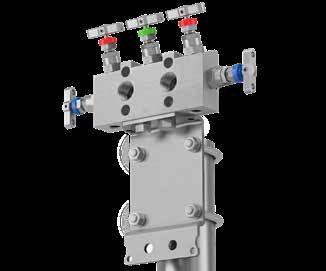
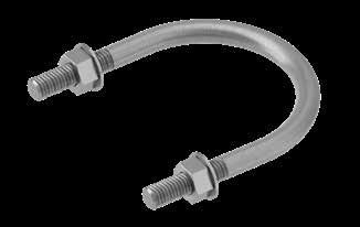
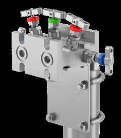
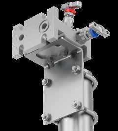
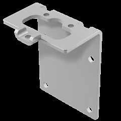
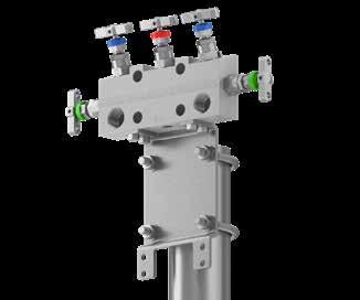
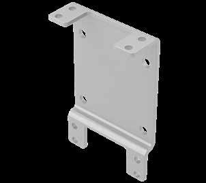
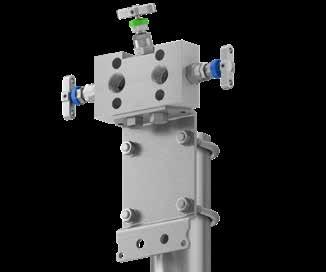
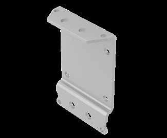
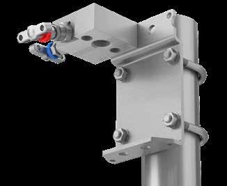
4-OFF Ø8.5 [Ø0.33"] MTG. HOLES 69.5 (2.74)
4-OFF Ø8.5 [Ø0.33"] MTG. HOLES
120.0 [4.72]
120.0 [4.72]
48 Mounting Brackets Brackets for direct mount manifolds Brackets for 2, 3 and 5-valve direct mount manifolds - BKT3 • Universal manifold mounting bracket, suitable for all direct mount manifolds • This bracket design enables horizontal or vertical instrument positioning 49 ‘U’ bolt with nuts and washers for 2” NB standpipe Brackets for 5-valve direct mount HD*5 style manifolds with increased process centres - BKT5 • Universal manifold mounting bracket, suitable for all direct mount manifolds • This bracket design enables horizontal or vertical instrument positioning Item Part Number Suitable for Manifold Type Bracket material: Carbon Steel Bracket material: Stainless Steel Bracket with M8 ‘U’ Bolts and manifold Bolt Kit (Nuts and washers: M6 x 12 Bolt (4-OFF) BKT5CSB6 BKT5SSB6 HD*5CT HD*5 How to order: Brackets for 2, 3 and 5-valve direct mount extruded manifolds - BKT4 Item Part Number Suitable for Manifold Type Bracket material: Carbon Steel Bracket material: Stainless Steel 2-valve 3 & 5-valve Bracket with M8 ‘U’ Bolt and manifold Bolt Kit (Nuts and washers: M6 x 45 Bolt (3-OFF) BKT4CSB4BKT4SSB4 HEH*2 HET*2 HET*3 HEH*3 HET*5 HET*5CT HEH*5 HEH*5CT How to order: 90.0 [3.54] 69.5 [2.74] 35.0 [1.38] 4-OFF Ø8.5 [Ø0.33"] MTG. HOLES 69.5 [2.74] 10.0 [0.39] 145.0 [5.71] How to order: Item Part Number Suitable for Manifold Type Bracket material: Carbon Steel Bracket material: Stainless Steel 2-valve3 & 5-valve Bracket with M8 ‘U’ Bolts and manifold Bolt Kit (Nuts and washers: M10 x 12 Bolt (2-OFF) BKT3CSB2BKT3SSB2 HD*3M HD*3MDTP HD*3MFF HD*3 HD*5M HD*5MFF Bracket with M8 ‘U’ Bolts and manifold Bolt Kit (Nuts and washers: M10 x 12 Bolt (1-OFF) M6 x 12 Bolt (1-OFF) BKT3CSB3BKT3SSB3 HD*2M HD*2MFF 90.0 [3.54] 145.0 [5.71] 69.5 [2.74] 35.0 [1.38] 69.5 [2.74] 90.0 [3.54] 145.0 [5.71] 69.5 [2.74] 35.0 [1.38] 69.5 [2.74] 35.0 (1.38) 90.0 (3.54) 69.5 (2.74) 145.0 (5.71) 69.5 (2.74)
10.0 (0.39)
145.0 (5.71)
Introduction
Suitable for vertical or horizontal installation, these base connection, base mounted manifolds can be utilised in stand-alone applications, but are especially suited for installation with transmitters within an instrument protection enclosure. They offer many benefits, including the ability to complete all connections outside of the enclosure itself. Combined with Parker’s own instrument enclosure solutions and specified with the Parker Superior Advantage integral tube fitting connections, these represent the simplest, most efficient and reliable installation solutions available when protection is required.

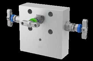
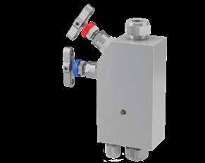
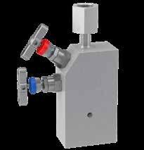
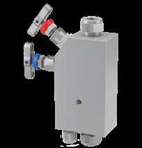
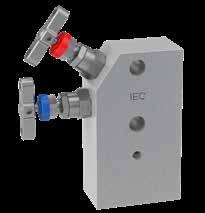
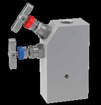
16284 as it applies to the union of nipple and nut themselves.
• Union nut also conforms generally to DIN EN 837 for the gauge connection itself, as it applies to the union of nipple and nut themselves.
50
Connected Manifolds Especially Suited For Enclosure Mounting
Base
- Female x Female threaded - NPT HL*2EXT - Integral A-LOK® connections HD*2EXT - Female threaded - NPT x Flanged HL*2EXTWG - Female threaded - NPT with integral swivel gauge adaptor D A B C D E Instrument Bleed/TestProcess Pressure (PSI) InletOutlet Bleed /test Dimension NPTNPTNPT A mm (inch) B mm (inch) C mm (inch) D mm (inch) E mm (inch) 6,0001/2” F1/2”F1/4” F 63.5 (2.50) 114.3 (4.50) 38.1 (1.50) 114.3 (4.50) 145.5 (5.73) B A B C D E A B C D E
HL*2EXT
tube
to inlet, outlet
vent/drain/bleed. *In accordance with DIN 16284 - Swivel BSPP 1/2” Female • Swivel adaptor
outlet
socket weld,
conforming to ANSI B16.11. •
qualified welder.
qualification, certification, documentation
support. •
DIN
Example shown: 2-valve base mounted manifold especially suited for use within enclosures, having Parker Superior Advantage fully integrated inverted style
connections
and
to the
is provided through a
generally
Weld connection is a “commercial weld”, completed by a
Any specific
or additional NDT, will require to be engineered and quoted extra – please consult your local Parker
Union nut dimensions generally conform to
B D E E A C D B 51 HD*3EXT - Female threaded - NPT x Flanged InletOutlet Drain/Bleed/ Test Dimension A mm (inch) B mm (inch) C mm (inch) D mm (inch) E mm (inch) 1/2” NPTFlangedOptional114.3 (4.50)215.9 (8.50)88.9 (3.50)38.1 (1.50)114.3 (4.50) d p A B A B D A B C D E HD*5EXT - Female threaded - NPT x Flanged Test/ drain ProcessTest/ drain InletOutletDrain/Bleed/Test Dimension A mm (inch) B mm (inch) C mm (inch) D mm (inch) E mm (inch) F mm (inch) 1/2” NPTFlanged1/4” NPT114.3 (4.50)215.9 (8.50)88.9 (3.50)38.1 (1.50)114.3 (4.50)145.5 (5.73) A B C D E F Manifold base footprint dimensions Notes: • Recommended base enclosure plate thickness to suit above footprints: 3-5mm. • Optional variations of these manifold types include compatibility for Emerson CoplanarTM transmitters. Please note, footprint dimensions for the 2-valve equivalents do vary. For further details see page 55. Manifold footprint for 2-valve manifolds. Example shown: HDS2EXT Manifold footprint for 3 & 5-valve manifolds. Example shown (5-valve): HDS5EXT ItemDescription 1Manifold outlet to transmitter interface 38.0 [1.50] 38.0 [1.50] 25.0 [0.98] 3-OFF M8x1.25p MTG. HOLES 38.0 [1.50] 87.0 [3.43] 38.1 [1.50] 114.3 [4.50] MANIFOLD FOOTPRINT FOR 3 & 5 VALVE EXAMPLE SHOWN - 5 VALVE 'HDS5EXT' 63.5 [2.50] MANIFOLD FOOTPRINT FOR 2 VALVE EXAMPLE SHOWN - HDS2EXT 38.1 [1.50] 38.0 [1.50] 19.2 [0.75] 19.2 [0.75] 2-OFF M8x1.25p MTG. HOLES 6.6 [0.26] 13.7 [0.54] 11.1 [0.44] 2-OFF 1/4-18 NPT (FEM) VENT/DRAINS 1/4-18 NPT (FEM) VENT/DRAIN 13.7 [0.54] 11.1 [0.44] 6.4 [0.25] 19.0 [0.75] 1/2-14 NPT (FEM) CONNECTION 2-OFF 1/2-14 NPT (FEM) CONNECTION NOTES: 1.Manifold outlet to transmitter interface 2.Recommended base enclosure plate thickness 3-5mm to suit above footprints. NOTE 1. NOTE 1. 1 2-OFF M8x1.25p MTG. HOLES 1/2-14 NPT (FEM) CONNECTION 1/4-18 NPT (FEM) VENT/DRAIN 63.5mm (2.50”) 13.7mm (0.54”) 11.1mm (0.44”) 19.0mm (0.75”) 38.1mm (1.50”) 6.6mm (0.26”) 19.2mm (0.75”) 38.0mm (1.50”) 6.4mm (0.25”) 38.0 [1.50] 38.0 [1.50] 25.0 [0.98] 3-OFF M8x1.25p MTG. HOLES 38.0 [1.50] 87.0 [3.43] 38.1 [1.50] 114.3 [4.50] MANIFOLD FOOTPRINT FOR 3 & 5 VALVE EXAMPLE SHOWN - 5 VALVE 'HDS5EXT' 63.5 [2.50] MANIFOLD FOOTPRINT FOR 2 VALVE EXAMPLE SHOWN - HDS2EXT 25.0 [0.98] 38.1 [1.50] 38.0 [1.50] 19.2 [0.75] 19.2 [0.75] 2-OFF M8x1.25p MTG. HOLES 6.6 [0.26] 6.6 [0.26] 13.7 [0.54] 11.1 [0.44] 2-OFF 1/4-18 NPT (FEM VENT/DRAINS 1/4-18 NPT (FEM) VENT/DRAIN 13.7 [0.54] 11.1 [0.44] 6.4 [0.25] 19.0 [0.75] 1/2-14 NPT (FEM) CONNECTION 2-OFF 1/2-14 NPT (FEM) CONNECTION NOTES: 1.Manifold outlet to transmitter interface 2.Recommended base enclosure plate thickness 3-5mm to suit above footprints. NOTE 1. NOTE 1. 1 2-OFF 1/2-14 NPT (FEM) CONNECTION 3-OFF M8x1.25p MTG. HOLES 2-OFF 1/4-18 NPT (FEM) VENT/DRAINS 25.0mm (0.98”) 38.1mm (1.50”) 38.0mm (1.50”) 38.0mm (1.50”) 19.2mm (0.75”) 6.6mm (0.26”) 11.1mm (0.44”) 13.7mm (0.54”) 114.3mm
87.0mm
38.0mm
Process Pressure (PSI) InletOutlet Bleed /test Dimension A-LOKA-LOKA-LOK A mm (inch) B mm (inch) C mm (inch) D mm (inch) E mm (inch) 6,000 1/2” 12mm 1/2” 12mm 1/4” 6mm 63.5 (2.50) 114.3 (4.50) 38.1 (1.50) 114.3 (4.50) 145.5 (5.73) Pressure (PSI) InletOutlet Bleed /test Dimension NPTBSPP*NPT A mm (inch) B mm (inch) C mm (inch) D mm (inch) E mm (inch) 6,0001/2” F1/2”F1/4” F 63.5 (2.50) 114.3 (4.50) 38.1 (1.50) 114.3 (4.50) 162.8 (6.40) Pressure (PSI) Inlet Outlet Bleed /test Dimension NPT NPT A mm (inch) B mm (inch) C mm (inch) D mm (inch) E mm (inch) 6,0001/2” FFlanged1/4” F 63.5 (2.50) 114.3 (4.50) 38.1 (1.50) 114.3 (4.50) 145.5 (5.73)
(4.50”)
(3.43”)
(1.50”)
5
Series
HL Pipe to pipe/Thread to thread connections1
HD Pipe/Thread to IEC flange connection2
1 2-valve manifolds only.
2 Default standard connections for pipe/thread to flange are: 1/2” NPT Fem. inlet with DIN IEC
B outlet transmitter face with 1/4” NPT Fem. vents/drains/bleeds/purge or test ports - where specified.
WG Integral swivel gauge connection - 1/2" BSPP (HL*EXT versions only)5
CT Suitable for fiscal metering/custody transfer applications (5-valve versions only)
DTP Downstream test ports - 1/4” NPT only (3-valve versions only)
• Swivel adaptor to the outlet is provided through a socket weld, generally conforming to ANSI B16.11.
• Weld connection is a “commercial weld”, completed by a qualified welder. Any specific qualification, certification, documentation or additional NDT, will require to be engineered and quoted extra – please consult your local Parker support.
• Union nut dimensions generally conform to DIN 16284 as it applies to the union of nipple and nut themselves.
• Union nut also conforms generally to DIN EN 837 for the gauge connection itself, as it applies to the union of nipple and nut themselves.
6 As standard, valves with Female Socket Weld connections will be of the same length as per the equivalent NPT pipe threaded variants.
IVAM104F
• 10mm CPI inverted inlet & 1/4” NPT Fem. vent/drain = IVZM104F
• 12mm A-LOK inverted inlet & 6mm vent/drain = IVAM126
5-valve barstock base mounted manifold for direct connection to instrument, manufactured from 316 Stainless Steel material having 1/2” NPT Fem. process inlet connections with DIN IEC B outlet flange and 1/4” NPT Fem. vent/drain/bleed. Gland packing is PTFE.
2-valve barstock base mounted manifold for direct connection to instrument, manufactured from 316 Stainless Steel material having 1/2” NPT Fem. process inlet connections with DIN IEC B outlet flange and 1/4” NPT Fem. vent/drain/bleed. Gland packing is PTFE.
3-valve barstock base mounted manifold for direct connection to instrument, manufactured from 6MO Super Aust. St. St. material having 1/2” NPT Fem. process inlet connections with DIN IEC B outlet flange. Gland packing is Graphite. Additional 1/4” NPT Fem. downstream test con. are provided and there is Anti-tamper operating for the equalise function.
5-valve barstock base mounted manifold for direct connection to instrument, manufactured from Monel 400 CRA material having 1/4” NPT Fem. process inlet connections with DIN IEC A outlet flange and 1/4” NPT Fem. vent/drain/bleed. Gland packing is PTFE. Materials are compliant with NACE, the manifold is cleaned suitable for Oxygen service and the vent valves have Anti-tamper operation with keys.
2-valve barstock base mounted manifold for remote connection to instrument, manufactured from 316 St. St. material having 1/2” NPT Fem. process inlet connections with 1/2” BSPP outlet connection to instrument (with integral welded swivel gauge) and 1/4” NPT Fem. vent/drain/bleed. Gland packing is PTFE and a 1/4” NPT blanking plug is provided. 2-valve barstock base mounted manifold for remote connection to instrument, manufactured in 316 St. St. material having Parker Superior Advantage fully integrated, inverted style 1/2” CPI tube connections to process inlet and instrument outlet, with 1/4” NPT Fem. vent/drain/bleed. Gland packing is Graphite; there is Anti-tamper operation to the equalise valve and a 1/4” NPT bleed valve plug is supplied.
5-valve barstock base mounted manifold for direct connection to instrument, manufactured from 316 St. St. material having Parker Superior Advantage, 12mm PTFree male tube connectors to the process inlet connections, with DIN IEC A outlet flange and 6mm PTFree male tube connectors to vent/drain/bleed. Gland packing is PTFE, the valves have a PEEK soft tip and materials are compliant to NACE.
10 Carbon Steel bolt as standard. No designator required.
11 Extra length bolts to be specified when utilising these manifolds with Emerson CoplanarTM type transmitter with the traditional adaptor flange.
12 Not required when Firesafe design option (FS) selected.
13 Not available for PCTFE Soft Tip 9 or Oxygen use OX).
14 3,000 PSI/207 BAR only. See main catalogue page.
15 Plugs supplied loose in a packing box. See main catalogue page.
16 These options can be specified to independent valves:
Add E to specify assembly to Equalise valve only.
Add I to specify assembly to Isolate valves.
Add V to specify assembly to Vents/Drains/Bleeds.
Examples:
• HWV = Handwheel to Vents/Drains/Bleeds.
• ATE = Anti-Tamper to Equalise valve.
17 Anti-Tamper operation and no Key.
18 Anti-Tamper operation and one Key supplied per manifold.
19 Specify quantity required as separate line item.
IMPORTANT NOTES:
• For optimum results in integral tube connections on manifolds, the use of Parker pre-assembly tooling is highly recommended. For inverted style integral tube connections the use of Parker pre-assembly tooling is mandatory.
• Not all options/combinations are available in each single product model type.
• We reserve the right to review/revise this part number structure at any time. If necessary, we can refuse and/or recommend the most suitable alternative part number(s). We may also apply MOQ rules.
• Should your part number selection exceed 25 characters in length when completed, then it is likely to be incorrect, please consult your local Parker representation for assistance.
• If in any doubt, please consult your local Parker representation.
53 Base Connected Manifolds Especially Suited For Enclosure Mounting Ordering information Materials S 316/316L Stainless Steel HC Hastelloy C276 6MO 6MO Sup. Aust. St.Steel T Titanium Gr. 23 M Monel 4003 825 Inconel 825 D1 Duplex 22 Cr. Steel 625 Inconel 625 D2 Super Duplex 25 Cr. Steel C Carbon Steel4 Example
HDS5EXT
HLS2EXT
HD6MO3EXTDTP
HLS2EXTWG P
HLS2EXT
1 (Default): HDS5EXT
Example 2 (Default): HDS2EXT
Example 3: HD6MO3EXTDTP3ATE
3ATE Example 4: HDM5EXT4NDAATKVOXNC HDM5EXT 4NDAATKVOXNC Example 5: HLS2EXTWGP
Example 6: HLS2EXTIVZI83BVATE
IVZI83BVATE Example 7: HDS5EXTDAPFCAM126PKNC HDS5EXTDAPFCAM126PKNC
Number of Valves/Configuration
2 2-valve, block & bleed/isolate & calibrate/vent/drain 3 3-valve, isolate & equalise for DP applications 5 5-valve, isolate, equalise & calibrate/bleed/vent/drain for DP applications 3 This material selection down-rates manifold. 4 For Carbon Steel consult your local Parker representation.
Application Configuration
EXT Mandatory designator for Base Mounted Manifolds
OPTIONS Instrument Bolt Options SB 316 Stainless Steel bolt10 CB 3” long Carbon Steel bolt11 CSB 3” long 316 Stainless Steel bolt11 Gland Packing Options 3 Graphite12 FS Firesafe design13 Seating Options - Needle Valves only RT Regulating/Metering Tip ST Stellite Tip 9 PCTFE Soft Tip14 PK PEEK Soft Tip Plug/Bleed Valve Options15 P Blank Plug BV Bleed Valve/Plug PBV Blank Plug and Bleed Valve/Plug Operator Options16 HW Handwheel LHW Handwheel Locking THL T Bar Locking AT* Anti-Tamper17 ATK* Anti-Tamper with Key18 ATHKEY Anti-Tamper Key19 Other Options OX Cleaned & lubricated for Oxygen use NC NACE MR-01-75 Compliant 52
Examples:
10mm A-LOK
12mm
Default
8
•
tube stub con. inlet & 1/4” NPT Fem. vent/drain = PFAM104F •
A-LOK male union con. inlet & 6mm A-LOK vent/drain = PFCAM126 *
standard connection; no designator required. Examples: HLS2EXT HDS5EXT.
As connection selections vary, further designation is required. Examples: • 1/2”BSPP Fem. inlet, 1/2” BSPT outlet & 1/4” BSPT Fem. vent/ drain/bleed = 8R8K4K • 1/2” BSPP Fem. inlet, DIN IEC B outlet & 1/4” NPT Fem. vent/ drain/bleed = 8R4F 7 Examples: • 10mm A-LOK inverted inlet & 1/4” NPT Fem. vent/drain =
Connections - Standard Options Inlet Outlet Vent/Drain/Bleed/ Test/Purge HL Remote StyleHD Direct Style
NPT
NPT Fem.DIN IEC B Flange1/4" NPT Fem. 4N 1/4” NPTFem.1/4” NPT Fem.DIN IEC B Flange1/4" NPT Fem. 4K 1/4” BSPT Fem.1/4” BSPT Fem.DIN IEC B Flange1/4" BSPT Fem. 4R 1/4” BSPP Fem.1/4” BSPP Fem.DIN IEC B Flange1/4" BSPP Fem. 8K 1/2” BSPT Fem.1/2” BSPT Fem.DIN IEC B Flange1/4" BSPT Fem. 8R 1/2” BSPP Fem.1/2” BSPP Fem.DIN IEC B Flange1/4" BSPP Fem. SW8 1/2” NB Fem. SW6 1/2” NB Fem. SW6 DIN IEC B Flange1/4" NPT Fem. DA 1/2” NPT Fem.N/A DIN IEC A Flange1/4" NPT Fem. Optional Connections Type Fitting Unit Inlet Outlet Vent/Drain/Bleed/ Test/Purge HL Remote Style HD Direct Style IV Inverted Connection Tube OD7 PF PTFree connect tube stub8 PFC PTFree connect male union8 A A-LOK Z CPI M Metric 6 6mm 10 10mm 12 12mm 6 6mm 10 10mm 12 12mm DIN IEC Flange 4F 1/4” NPT Fem.9 I Imperial 4 1/4” 6 3/8” 8 1/2” 4 1/4” 6 3/8” 8 1/2” 9 1/4” NPT Fem. is default standard for bleed/vent/drain, some model types may be available with other connections.
* 1/2”
Fem.1/2”
Introduction
As either stand-alone or as complementary to the EXT style manifolds, Parker instrument enclosure solutions consist of a comprehensive range to suit a wide array of instrumentation applications. The enclosures have a shiny gel-coat external finish that is the same as used in the construction of boats and marine vessels. This enables Parker enclosures to withstand the demands of hostile environments.
Fully assembled systems can be supplied based on your specific project or site requirements. They can be fitted with various pressure or flow measuring instruments and manifolds and a host of other features and accessories.
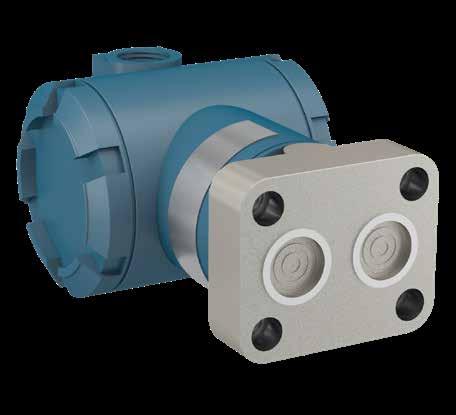
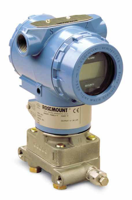
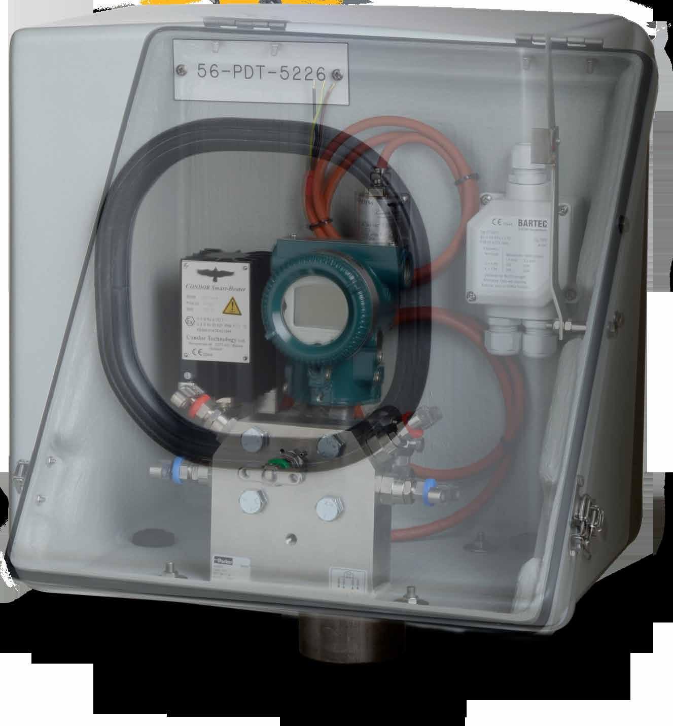
For full details of this range and accessories see catalogue ref. 4190-ENC.
Manifolds for
CoplanarTM Transmitters
These are the only direct mount manifolds in the range not to comply with the IEC standard. These Parker ‘integral’ style manifolds are uniquely designed for connection to the non-traditional Emerson/ RosemountTM CoplanarTM transmitter models and are not suitable for use with the traditional IEC compliant models of this, or other brands.
In this scenario, the assembled manifold/transmitter combination has the advantage of more compact overall dimensions and reduced weight. Typically, these assemblies are wall-mounted or mounted utilising a 2” NB pipestand.
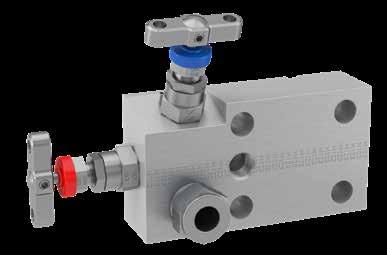
Compatibility of the Parker integral manifold is assured, having been designed and rigorously tested with all the Emerson/RosemountTM CoplanarTM transmitters, such as 2051 and 3051 models.
Example shown: 2-valve block and bleed direct mount manifold suitable for Emerson/RosemountTM CoplanarTM transmitter with Parker Superior Advantage fully integrated inverted A-LOK® tube fitting connections.
Recognising and understanding the Emerson specific CoplanarTM transmitter
Manifold mounts here
Note the Emerson proprietary non-IEC compliant interface and the smaller seal center dimensions (33mm)
3051 DP transmitter, shown with the Emerson flange adapter in lieu of a manifold. A directly mounted Parker CoplanarTM manifold, replaces this.
54 55
Instrument Enclosure Solutions
1 8 9 10 5 4 7 6 2 11 3 ItemDescription 1Parker Enclosure 2Identification Label 3Thermostat 4Finned Space Heater 5Viewing Window 6Mounting Hub (for 2” NB Pipe Stand) 7Propstay 8Junction Box 9Transmitter 10Parker Manifold 11Instrument and Signal Cable Gland
Introduction 2051/3051
For these products interface seals are provided with the transmitter by Emerson 7/16” UNF threaded bolt holes on 54mm (2 1/8”) x 41mm (1 5/8”) bolt mounting centres
3051 DP transmitter, shown with the Emerson flange adapter removed.
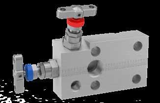
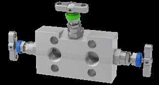
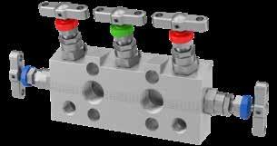
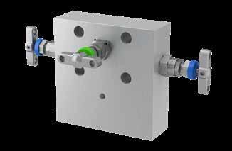
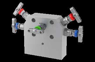
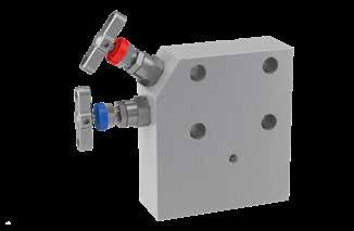
56 57 A B D A B C D E InletOutletBleed/Test Dimension A mm (inch) B mm (inch) C mm (inch) D mm (inch) E mm (inch) 1/2”NPTFlanged1/4” NPT110.0 (4.33)160.8 (6.33)28.6 (1.13)63.5 (2.50)107.6 (4.24) HD*2MCP - Female threaded - NPT x Flanged HD*3MCP - Female threaded - NPT x Flanged HD*5MCP - Female threaded - NPT x Flanged d p Test/ drain ProcessTest/ drain InletOutletBleed/Test Dimension A mm (inch) B mm (inch) C mm (inch) D mm (inch) E mm (inch) F mm (inch) 1/2” NPTFor 3051Optional33.0 (1.30)110.0 (4.33)211.6 (8.33)28.6 (1.13)63.5 (2.50)107.6 (4.24) InletOutletBleed/Test Dimension A mm (inch) B mm (inch) C mm (inch) D mm (inch) E mm (inch) F mm (inch) 1/2” NPTFlanged1/4” NPT33.0 (1.30)138.0 (5.43)239.6 (9.43)28.6 (1.13)63.5 (2.50)107.6 (4.24) Instrument Bleed/TestProcess C A B E A B C D E F A B C D E F Process Instrument Instrument Manifolds for 2051/3051 CoplanarTM Transmitters HD*2MCPEXT - Female threaded - NPT x Flanged HD*3MCPEXT - Female threaded - NPT x Flanged HD*5MCPEXT - Female threaded - NPT x Flanged A B C D E Instrument Bleed/TestProcess InletOutletBleed/Test Dimension A mm (inch) B mm (inch) C mm (inch) D mm (inch) E mm (inch) 1/2”NPTFlanged1/4” NPT101.6 (4.00)151.8 (5.98)38.1 (1.50)114.3 (4.50)145.5 (5.73) A B C D E d p InletOutlet Drain/Bleed/ Test Dimension A mm (inch) B mm (inch) C mm (inch) D mm (inch) E mm (inch) 1/2” NPTFlangedOptional114.3 (4.50)215.9 (8.50)88.9 (3.50)38.1 (1.50)114.3 (4.50) A B C D E F Test/ drain ProcessTest/ drain InletOutlet Drain/Bleed/ Test Dimension A mm (inch) B mm (inch) C mm (inch) D mm (inch) E mm (inch) F mm (inch) 1/2” NPTFlanged1/4” NPT114.3 (4.50)215.9 (8.50)88.9 (3.50)38.1 (1.50)114.3 (4.50)145.5 (5.73) Process Instrument Instrument
1 Default standard connections for pipe/thread to flange are: 1/2” NPT Fem. inlet with 2051/3051
CoplanarTM outlet flange and 1/4” NPT Fem. vents/drains/bleeds.
MCP Mandatory designator defining barstock manifold with traditional inlet centres and 2051/3051 CoplanarTM transmitter interface flange
5-valve barstock manifold for direct connection to instrument, manufactured from 316 Stainless Steel material having 1/2” NPT Fem. process inlet connections with 2051/3051 CoplanarTM compliant outlet flange and 1/4” NPT Fem. vent/drain/bleed. Gland packing is PTFE.
3-valve barstock manifold suitable for base mounting and for direct connection to instrument, manufactured from 6MO Super Austenitic St. St. material having 1/2” NPT Fem. process inlet connections and 2051/3051 CoplanarTM compliant outlet flange. Manifold also has 2 1/4” NPT Fem. downstream test ports. Gland packing is Graphite and the equalise valve has Anti-tamper operation and 1/4” NPT Fem. vent/drain/bleed.
5-valve barstock manifold for direct connection to instrument, manufactured from Monel 400 CRA material having 1/4” NPT Fem. process inlet connections with 2051/3051 CoplanarTM compliant outlet flange and 1/4” NPT Fem. vent/drain/bleed. Gland packing is PTFE, materials comply to NACE; manifold is cleaned suitable for oxygen service and vent valves are Anti-tamper operation with key.
5-valve barstock manifold for direct connection to instrument, manufactured from 316 St. St. material having Parker Superior Advantage 12mm A-LOK PTFree male union style process inlet connectons with 2051/3051 CoplanarTM compliant outlet flange. Vent/bleed/drain connections are also PTFree male union style but of 6mm size. Gland packing is PTFE, the valve complies with NACE and all valves have PEEK soft tip seating.
OPTIONS
Instrument Bolt Options SB 316 Stainless Steel bolt8 CB 3” long Carbon Steel bolt9 CSB 3” long 316 Stainless Steel bolt9
Gland Packing Options 3 Graphite10 FS Firesafe design11
Options - Needle Valves only
Regulating/Metering Tip
Stellite Tip
PCTFE Soft Tip12
PEEK Soft Tip
Valve Options13 P Blank Plug BV Bleed Valve/Plug PBV Blank Plug and Bleed Valve/Plug Operator Options14 HW Handwheel LHW Handwheel Locking THL T Bar Locking AT* Anti-Tamper15 ATK* Anti-Tamper with Key16 ATHKEY Anti-Tamper Key17 Mounting Options18 BK Assembled with Carbon Steel bracketry & bolts BKS Assembled with Stainless Steel bracketry &
8 Carbon Steel bolt as standard. No designator required.
9 Extra length bolts to be specified when utilising these manifolds with Emerson CoplanarTM type transmitter with the traditional adaptor flange.
10 Not required when Firesafe design option (FS) selected.
11 Not available for PCTFE Soft Tip 9 or Oxygen use OX).
12 3,000 PSI/207 BAR only. See main catalogue page.
13 Plugs supplied loose in a packing box. See main catalogue page.
14 These options can be specified to independent valves:
Add E to specify assembly to Equalise valve only.
Add I to specify assembly to Isolate valves.
Add V to specify assembly to Vents/Drains/Bleeds.
Examples:
• HWV = Handwheel to Vents/Drains/Bleeds.
• ATE = Anti-Tamper to Equalise valve.
15 Anti-Tamper operation and no Key.
16 Anti-Tamper operation and one Key supplied per manifold.
17 Specify quantity required as separate line item.
18 Mounting Options available on EXT option.
4N 1/4” NPTFem.2051/3051 Coplanar1/4" NPT Fem.
4K 1/4” BSPT Fem.2051/3051 Coplanar1/4" BSPT Fem.
4R 1/4” BSPP Fem.2051/3051 Coplanar1/4" BSPP Fem.
8K 1/2” BSPT Fem.2051/3051 Coplanar1/4" BSPT Fem.
8R 1/2” BSPP Fem.2051/3051 Coplanar1/4" BSPP Fem.
SW8 1/2” NB Fem. SW4 2051/3051 Coplanar1/4" NPT Fem.
IMPORTANT NOTES:
• For optimum results in integral tube connections on manifolds, the use of Parker pre-assembly tooling is highly recommended. For inverted style integral tube connections the use of Parker pre-assembly tooling is mandatory.
• Not all options/combinations are available in each single product model type.
• We reserve the right to review/revise this part number structure at any time. If necessary, we can refuse and/or recommend the most suitable alternative part number(s). We may also apply MOQ rules.
• Should your part number selection exceed 25 characters in length when completed, then it is likely to be incorrect, please consult your local Parker representation for assistance.
• If in any doubt, please consult your local Parker representation.
59 Manifolds for 2051/3051 CoplanarTM Transmitters Materials S 316/316L Stainless Steel HC Hastelloy C276 6MO 6MO Sup. Aust. St.Steel T Titanium Gr. 22 M Monel 4002 825 Inconel 825 D1 Duplex 22 Cr. Steel 625 Inconel 625 D2 Super Duplex 25 Cr. Steel C Carbon Steel3 Example 1 (Default): HDS5MCP HDS5MCP Example 2: HD6MO3MCPEXTDTP3ATE HD6MO3MCPEXTDTP 3ATE Example 3: HDM5MCP4NATKVOXNC HDM5MCP 4NATKVOXNC Example 4: HDS5MCPPFCAM126PKNC HDS5MCP PFCAM126PKNC
of Valves/Configuration
2-valve, block & bleed/isolate & calibrate/vent/drain 3 3-valve, isolate & equalise for DP applications 5 5-valve, isolate, equalise & calibrate/bleed/vent/drain for DP applications
This material selection down-rates manifold.
For Carbon Steel consult your
Parker representation.
Configuration
Extended body base mounting especially suitable for enclosures
Suitable for fiscal meterin/custody transfer applications. 5-valve versions only
Downstream test ports. 3-valve versions only. 1/4" NPT only Series
Flat barstock direct mount to
Number
2
2
3
local
Application
EXT
CT
DTP
HD
instrument manifolds with 2051/3051 CoplanarTM style outlet flange
58 6 Examples: • 10mm A-LOK tube stub con. inlet & 1/4” NPT Fem. vent/drain = PFAM104F • 12mm A-LOK male union con. inlet & 6mm A-LOK vent/drain = PFCAM126 * Default standard connection; no designator required. Examples: HDS2MCP HDS5CPEXT. As connection selections vary, further designation is required. Example: 1/2” BSPP Fem. inlet, 2051/3051 Coplanar & 1/4” NPT Fem. vent/drain/bleed = 8R4F 5 Examples: • 10mm A-LOK inverted inlet & 1/4” NPT Fem. vent/drain = IVAM104F • 10mm CPI inverted inlet & 1/4” NPT Fem. vent/drain = IVZM104F • 12mm A-LOK inverted inlet & 6mm vent/drain = IVAM126
Connections - Standard Options Inlet Outlet Vent/Drain/Bleed/Test/Purge
Seating
RT
ST
9
PK
Plug/Bleed
bolts Other Options OX Cleaned & lubricated for Oxygen use NC NACE MR-01-75 Compliant
4 As standard, valves with Female Socket Weld connections will be of the same length as per the equivalent NPT pipe threaded variants.
* 1/2” NPT Fem.2051/3051 Coplanar1/4" NPT Fem.
Optional Connections Type Fitting Unit InletOutlet Vent/Drain/ Bleed/Test/Purge IV Inverted Connection Tube OD5 PF PTFree connect tube stub6 PFC PTFree connect male union6 A A-LOK Z CPI M Metric 6 6mm 10 10mm 12 12mm 2051/ 3051 Coplanar 4F 1/4” NPT Fem.7 I Imperial 4 1/4” 6 3/8” 8 1/2” 7 1/4” NPT Fem. is default standard for bleed/vent/drain, some model types may be available with other connections. Ordering information
Introduction
•
Brackets for
•
Parker
Pressure Blanking Plug (Code
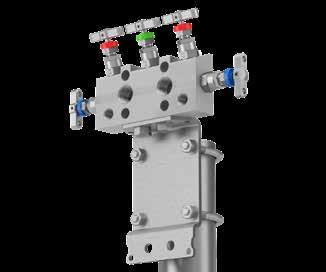
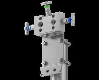
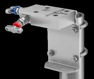
Threaded high quality pressure blanking plug used in manifolds for the blanking off the vent/drain/bleed/test calibration ports, but also available separately for use where any female port requires to be closed off.
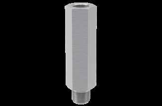

Other thread type and sizes may be available.
Threaded high quality pressure blanking plug, incorporating bleed screw and directional spout; widely used directly in association with the manifolds for the closure of vent/drain/bleed/test calibration ports, but allows the safe & controlled bleed/vent of enclosed process media. These compact bleed plugs are also available separately for use where any female port requires to be closed off and enclosed media is required to be bled off or vented.
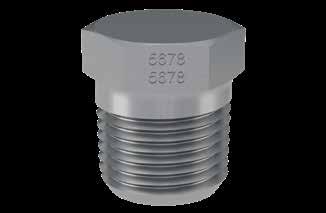
The bleed screw itself is captive within the plug, cannot be removed and cannot be ejected in proper use.
Other thread type and sizes may be available.
Compact Gauge Syphon
60 61 Manifolds for 2051/3051 CoplanarTM
Transmitters
Essential Manifold Accessories
To complement the entire manifold range and provide complete solutions for all applications, we offer the following accessory products. These are in addition to the wide range of brackets and mounting solutions found elsewhere in this catalogue (see pages 34, 40, 48, 49, 60).
can also offer a diverse portfolio of tube fitting solutions and other products, all manufactured to the same exacting standards. Please consult your local Parker representative for further details and information.
HBV) A discrete range of compact gauge syphons available in 1/2” NPS onlyplease
your local Parker support. Size Part Number 1/4” HPH*4M 1/2” HPH*8M * Specify material Size Part Number 1/4” HBV*4M 1/2” HBV*8M
HPH) Pressure Bleed Plug (Code
consult
* Specify material Materials S 316/316L Stainless Steel HC Hastelloy C276 6MO 6MO Sup. Aust. St.Steel T Titanium Gr. 2 M Monel 400 825 Inconel 825 D1 Duplex 22 Cr. Steel 625 Inconel 625 D2 Super Duplex 25 Cr. Steel Materials S 316/316L Stainless Steel HC Hastelloy C276 6MO 6MO Sup. Aust. St.Steel T Titanium Gr. 2 M Monel 400 825 Inconel
D1 Duplex 22 Cr. Steel 625 Inconel 625 D2 Super Duplex 25 Cr. Steel
825
2, 3 and 5-valve direct mount manifolds
Brackets for
- BKT3
Universal manifold mounting
suitable for all direct mount manifolds
bracket,
How to order: Item Part Number Suitable for Manifold Type Bracket material: Carbon Steel Bracket material: Stainless Steel 2-valve3 & 5-valve Bracket with M8 ‘U’ Bolts and manifold Bolt Kit (Nuts and washers: M10 x 12 Bolt (2-OFF) BKT3CSB2BKT3SSB2 HD*2MCP HD*3MCP HD*5MCP 90.0 [3.54] 145.0 [5.71] 69.5 [2.74] 35.0 [1.38] 69.5 [2.74] 90.0 [3.54] 145.0 [5.71] 69.5 [2.74] 35.0 [1.38] 69.5 [2.74] 35.0 (1.38) 90.0 (3.54) 69.5 (2.74) 145.0 (5.71) 69.5 (2.74) Image shown: Part No.:
Image shown: Part
Image
Ordering information: Ordering information:
This bracket design enables horizontal or vertical instrument positioning
HDS2MCPBK
No.: HDS3MCPBK
shown: Part No.: HDS5MCPBK Image shown: Part No.: BKT3SSB2
direct
mount manifolds
•
Example 1: HKSM12ASB3
HKSM12ASB3
Example 2: HK6MOIM12ASB3 HK6MOIM12ASB3
Example 3: HKD18FOSSB HKD18FOSSB
Example 4: HKSBW83 HKSBW83 Example 5: HK625BW8AXSB3 HK625BW8AXSB3


62 63 Essential Manifold Accessories
Instrument Flange Adaptors (Kidney/Oval Flanges)
OTHER NOTES: • Tube connection selection as per Parker recommended tube guides. • Flange interface connection to DIN IEC 61518 Type A. • Inverted A-LOK® connections supplied with Socket Cap Head bolts. All other connections supplied with Hex Head bolts. • Not all options/combinations are necessarily available in each single product model type. Care should be taken to consult the main catalogue. If in doubt, please consult your local Parker representation. Ordering information: Example shown with traditional 1/2” NPT Fem. connection. Materials S 316/316L Stainless Steel HC Hastelloy C276 6MO 6MO Sup. Aust. St.Steel T Titanium Gr. 2 M Monel 400 825 Inconel 825 D1 Duplex 22 Cr. Steel1 625 Inconel 625 D2 Super Duplex 25 Cr. Steel1 Butt Weld - Pipe TypeSize Schedule (Thickness) Extension BW Butt Weld 4 1/4" NB 6 3/8" NB 8 1/2" NB 12 3/4" NB * Sch.80 A Sch.160 B Sch.XXS * 25mm Y 75mm X 100mm Series HK Kidney Flange Options OS Offset 1.5mm option3 SB Stainless Steel Bolt option 3 Graphite Seal option5 NC NACE option 2 For CPITM change A to Z, example: M10Z 3 Offset option only available on Fem. threaded connection; accommodates variation of impulse line centres between 51-57mm. See diagram above. 4 Bolt material as standard HT Carbon Steel. Stainless Steel optional. Both in accordance with IEC 61518. 5 Interface seal material PTFE as standard. Graphite seal optional. Both in accordance with DIN IEC 61518 Type A. 1 Not available with tube connections. Connections 4F 1/4" NPT Fem. I4A 1/4” A-LOK Inverted 6F 3/8" NPT Fem. I6A 3/8” A-LOK Inverted 8F 1/2" NPT Fem. I8A 1/2” A-LOK Inverted 4A 1/4” A-LOK2 IM6A 6mm A-LOK Inverted 6A 3/8” A-LOK2 IM10A 10mm A-LOK Inverted 8A 1/2” A-LOK2 IM12A 12mm A-LOK Inverted M6A 6mm A-LOK2 M10A 10mm A-LOK2 M12A 12mm A-LOK2 * No designator required. A B D C 73.4 (2.89) 31.8 (1.25) 36.7 (1.44) 19.0 (0.75) A B D C 65.0 (2.56) 36.7 (1.44) 31.8 (1.25) 19.0 (0.75) Parker's
swivel gauge adaptors has
Example 1: SGS8M8F3HP SGS8M8F3HP Example
Ordering information: Materials S 316/316L Stainless Steel HC Hastelloy C276 6MO 6MO Sup. Aust. St.Steel T Titanium Gr. 2 M Monel 400 825 Inconel 825 D1 Duplex 22 Cr. Steel 625 Inconel 625 D2 Super Duplex 25 Cr. Steel1 Series SG Swivel gauge adaptor Options 3 Graphite Seal option1 HP High Pressure 10,000 PSI option NC NACE option Connections - Standard Inlet Outlet 4M 1/4" NPT Male 4F 1/4" NPT Fem. 6M 3/8" NPT Male 6F 3/8" NPT Fem. 8M 1/2" NPT Male 8F 1/2" NPT Fem. 4M 1/4" NPT Male 4M 1/4" NPT Male 6M 3/8" NPT Male 6M 3/8" NPT Male 8M 1/2" NPT Male 8M 1/2" NPT Male
Gauge Adaptors Features
Silver plated swivel thread and bearing surface to prevent thread galling and maximising re-make opportunities
Variety of thread options
Compact design
Fully contained and retained sealing mechanism Specification
316 Stainless Steel material as standard
Maximum pressure rating: 6,000 psig (414 barg)
Maximum temperature rating: 260°C (500°F)
Fully heat code traceable
range of
been designed to provide 360° rotational movement enabling maximum positional orientation of installed gauges and measuring instruments. A fully contained sealing mechanism ensures total system integrity and offers the user up to 10,000 psig (690 barg) working pressure. Silver plated swivel nut thread and bearing area prevent threat galling of stainless steel threads and allow trouble free repeatable re-assembly.
2: SGS8RDM8RFNC SGS8RDM8RFNC
Swivel
•
•
•
•
•
•
•
the instrument flange adaptor with 1.5mm offset connection (Code OS) which accommodates variation of impulse
51-57mm. 1 Interface seal material PTFE as standard. Graphite seal optional. Both in accordance with DIN IEC 61518 Type A. Example shown with integral A-LOK® connection. Example shown with inverted integral A-LOK® connection. 41.3 [1.63] 1.5 [0.06] OFFSET 11.8 12.0 1/2-14 NPT (FEM) 63.5 [2.50] 28.0 [1.10] 2.4 [0.09] 28.0 (1.10) 2.4 (0.09) 41.3 [1.63] 1.5
11.8
2
3
* Insert size designator. # Insert specification K/R RD). Other Connection Options *#F Fem. connection *#M Male connection K BSPT BS21, ISO7/1 - British Standard Taper Pipe thread R BSPP BS2779 - British Standard Parallel Pipe thre RD DIN 16284/16288/EN837 BSPP gauge connection type
Example of
line centres between
[0.06] OFFSET
12.0 1/2-14 NPT (FEM) 63.5 [2.50] 31.8 [1.25] 28.0 [1.10] 2.4 [0.09] 31.8 (1.25) 63.5 (2.50) 12.0 11.8 Ø 1/2-14 NPT (FEM) 41.3 (1.63) 1.5 (0.06) OFFSET 1 2 3 ItemDescription 1 IEC A connection to manifold
1/2” NPT Fem. connection to process inlet
1.5mm (0.06”) offset
Other Manifold Products
IntroductionProportional Relief Valves - HPRV Series
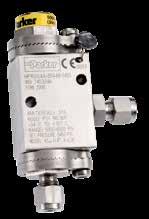
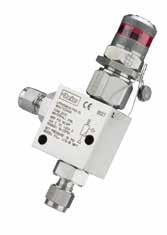

This range of exceptional Pressure Relief Valves (HPRV) provides an automatic protection mechanism for process instrumentation systems. CE-marked and certified to the highest Category-IV level of the Pressure Equipment Directive (PED), the HPRV valve’s design provides users with accurate and consistent cracking and resealing operation.
For full details see Catalogue ref. 4190-HPRV.
Check Valves - Hi-Check Series

These rugged high performance non-return valves offer the user a cold working pressure rating up to 10,000 psi. The true metal-sealed twopiece design ensures potential leakage points are kept to a minimum. As with our manifold range, we can offer the Parker Superior Advantage of integral tube connections. This further avoids system contamination, reduces potential leakage, weight, space and installation cost.
For full details see Catalogue ref. 4190-CV.
Needle Valves 20,000 PSI
This highest performing H-Series needle valve has been purpose designed for operation with any fluid up to 20,000 psi (1379 bar) rating. Complete with standard PTFE gland packing and non-rotational tip, it gives the user assurance of total in-service sealing security. 100% repeatable bubble tight shut off and Tru-Loc® gland adjuster security are key features of this design. A range of end connections is offered and includes the innovative Phastite® ferrule-less tube fitting or the market-leading Parker Autoclave Medium Pressure Cone & Thread –the ultimate Parker Superior Advantage combination. Additional options include NACE compatibility and heat code traceable materials.


For full details see Catalogue ref. 4190-HH/20K.
Large Bore Needle Valves
Another rugged high performer, this safe, reliable product was developed to operate across a wide pressure and temperature range, in dirty or hydrate service conditions. This Large Bore Needle / Globe Isolation Valves provide reliable bubble tight isolation, with significantly reduced risk of blocking compared to conventional needle valves. This full 1/2” (12.7mm) bore metal seated globe style needle isolation hand valve is available in 316L Stainless Steel or Duplex materials. It complies with ASME VIII ASME/ANSI B16.34 piping class specifications and is ruggedly constructed with a bolted body & bonnet interface.
For full details see Catalogue ref. 4190-HH/LBV.
Distribution Manifolds - HCDM Series
Based exclusively around the H series needle valve design, this compact distribution manifold offers operating pressures up to 6,000 psi for a wide selection of process media. It is available as standard in 316L Stainless Steel material with five or ten outlets, and is ideal for use where high performance is required and space is limited. Bore size through the valves is 4mm as standard; operation is with anti-tamper key, which further enhances the compact design.


For full details see Catalogue ref. 4190-DM.
Distribution Manifolds - HDM
Based entirely around the H-series complete bonnet assemblies, this distribution manifold offers operating pressures up to 6,000 psi for a wide selection of process media. It is available as standard in 316L Stainless Steel material and offers a choice of outlets from 4 to 20. Bore size through the valves is 4mm.

For further details consult your local Parker support.
Condensate Pots
Primary used to increase the accuracy of flow measurement in steam pipelines, these condensate pots provide an interface between the vapour phase and the condensed phase in the impulse lines. These condensate pots are available in a range of materials and have been designed in accordance with ASME VIII Div 1, and are produced in an ASME coded workshop. All condensate pots are CE-marked to PED 2014/68/EU for use with Group 2 gases. Typical industry applications include: refineries, power plants, chemical and petrochemical, steel plants and other process industries.
For full details see Bulletin ref. 3010-CP.
Close Coupled Instrument Mounting Systems - CCIMS
These ultimate complete manifold system solutions have been developed to meet constant demand for higher performance in flow measurement. They represent a standardised, yet radical breakthrough for direct coupling of pressure transmitters to pipelines.
CCIMS offers the following benefits:
• Reduced installation
• Reduced ownership cost

• Increased safety
• Lower maintenance
• Dramatically increased process measurement accuracy.
For full details see Catalogue ref. 4190-CCIMS.
64 65
Customer Specific Manifold Solutions


Introduction Shell
Total Refining and Chemical
This catalogue describes the most versatile and comprehensive range of instrumentation manifolds available on the market today. We also understand certain customers and projects can often require custom solution to suit particular needs and we welcome requests in this regard for our consideration. In some circumstances, this can result in an entirely bespoke product range and catalogues. We are pleased to present the following examples.


As an EFA (Enterprise Frame Agreement) holder to Shell, we offer a complete range of manifolds and accessories, including all components for the Shell modular mounting system, fully conforming to the Shell MESC (Material and Equipment Standards and Code) specifications. For fully detailed information please refer to Catalogue ref. 4190-MESC or contact your local Parker representation.
Totally compliant to Total RC’s Contract GLOB-0560 and featuring innovative leak-free technologies through the use of Parker Superior Advantage integral tube fitting connections, as well as all welded flanged assemblies, we are proud to offer this unique manifold solutions range and all necessary associated equipment and accessories. These product solutions save significant engineering and installation costs for this demanding user of process instrumentation systems. For fully detailed information please refer to Catalogue ref. 4190-Total or contact your local Parker representation.
Catalogue ref. 4190-Total Manifolds Class 600 and 1500. Total RC THR RC INS 920. Contract: GLOB-0560


Catalogue ref. 4190-MESC

Shell MESC Compliant Slimline Monoflange, Monoflange (Ball) and Instrument Manifolds EFA: PT3740


67 66
Complementary Products for Complete Installation Solutions
Modular Valves - Pro-Bloc® Series
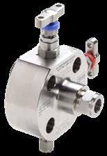
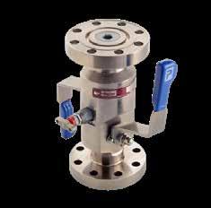
Designed to replace conventional multiple-valve installations currently in use for process measurement interfaces, these single-piece products combine multiple valve types into a single manifold. Potential leak paths are reduced and the mass of the system is lowered, reducing the stresses from loading and vibration. Additionally, these products also improve installation and operational safety factors, together with positive installation cost savings.
For full details see Catalogue ref. 4190-FP.
Monoflange Manifolds
More compact than Pro-Bloc® and adding to further space and weight saving, these monoflanges have primary, secondary and bleed valves assembled on the periphery of the flange. The manifold body can incorporate both O.S.&Y. and instrument needle valves as a mixture or all of the same type. These monoflanges are available from forged or bar stock material and can be certified as being of Firesafe design.
For full details see Catalogue ref. 4190-FP.
ALSO AVAILABLE AS ULTRA LOW EMISSION
Ball Valves and Manifolds Hi-Pro Series
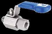
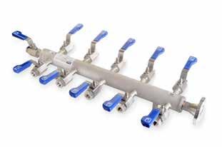
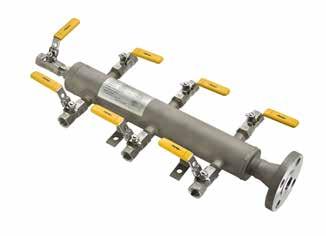
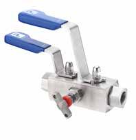
These high performance bi-directional Ball Valves & Manifolds offer the user full cold working pressure ratings up to 10,000 psi (689 bar), giving 100% bubble tight shut off and continuous repeatable performance. These products are suitable for the most demanding applications in the oil, gas and process control industries. All valves also meet the requirements of ANSI B31.1 for use in power plants. The design reduces potential body leakage paths to a minimum. With the added opportunity to select Parker Superior Advantage integral compression ends the user can eliminate the use of taper threads and thread sealant, thus avoiding system contamination, reducing leakage paths, installation costs, weight and space.
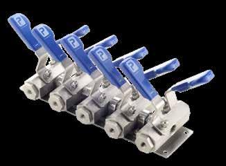
For full details see Catalogues ref. 4190-HBV and 4190-HBM.
Air Header Distribution Manifolds - LPAHM Series
These air header distribution manifolds are designed to distribute air from the compressor to the actuators on pneumatic instruments, such as steam flow meters, pressure controllers and valve positioners. They are widely used in industrial chemical processing, plastic processing and energy industries and are approved for low pressure applications up to 275 psi. Manufactured from AISI 316 Stainless Steel material, the air header distribution manifolds offer complete customer system compatibility that reduces installation time and potential leak paths. The coded welded construction with non-destructive tested design minimises the number of potential leak paths, rather than fabricating with instrumentation connections with tubing, therefore reducing labour costs. These manifolds are designed for use with air only and are supplied with a number of lockable ball valves on opposite sides, right side or left side only to prevent unauthorized access.
For full details see Catalogue ref. 4190-DM.
Air Header Distribution Manifolds - HPAHM Series
These distribution manifolds are designed for applications that use liquid or gas, low temperature steam and hydraulic actuation. The pressure rating of these manifolds is dictated by the inlet/outlet Flange Class or the thread connection. These distribution manifolds feature an ergonomic vinyl sleeve on the valve handle to provide positive grip and to ensure ease of operation. Each nut has an innovative domed design, which prevents ingress of moisture and contamination of the thread, therefore preventing corrosion. They feature a part-welded construction, with all welds carried out by coded welders, providing assurance of their robustness and performance. These manifolds are NDT (Non-Destructive Testing) applied, giving the customer greater assurance.
For full details see Catalogue ref. 4190-DM.
Hi-Pro Modular Distribution Manifold
Unique to Parker, these manifolds are the ideal choice when ultimate flexibility is required within a distribution manifold. They are approved to operate at pressures up to 6,000 psi and are used extensively in the oil, gas, chemical and petrochemical industries to provide safety and performance. These innovative Hi-Pro modular distribution manifolds can be easily arranged in a layout to suit a wide range of different applications to distribute liquid or gas. They use standard components, therefore making it more affordable for the customer. The Hi-Pro modular distribution manifolds feature an ergonomic vinyl sleeve on the valve handle to provide positive grip and to ensure ease of operation. Each nut is domed in shape, which prevents ingress of moisture and contamination of the thread, which could cause corrosion. This manifold is available with up to 20 valves (even numbers only - spare valves can be blanked off). Temperature range is up to 232OC with PEEK seats.
For full details see Catalogue ref. 4190-DM.
Lapped Joint Tube Adaptor
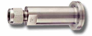
Available in the full range of fitting materials and sizes up to 1/2” (M12) as standard, these lapped joint tube adaptors are suitable for applications involving small flanged process valves and offer a simple, safe and effective conversion to instrument lines.
Flange Connector - Flange to Parker Tube Fittings
Offered in a range of materials and with either A-LOK® or CPITM tube fitting technology, these flange connectors deliver huge flexibility in terms of offering. Tube connections up to 1” (25mm), flange connections up to 2” NB and pressures to ANSI Class 2500 (6,000 PSI Nom.). The one-piece integral connection adaptors allow the safe, easy and efficient transition from process to instrumentation in just one step.
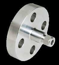
68 69
Complementary Products for Complete Installation Solutions
Parker Tube Ended Pressure Gauges
Parker Tube Ended Pressure Gauges monitor vacuum, compound, and positive system pressures up to 1000 psig. Available in lower mount and center back mount configurations, these 360°-positionable gauges are perfect for applications where space is at a premium. Not only do our Tube Ended Gauges do away with additional fittings, they completely eliminate the need for tape and sealants, making installation cleaner and quicker.
For full details see Bulletin ref. 4150-TEG.
Baumer Safety Pressure Gauges

Baumer’s safety pressure gauge MEP5 is specially designed for use in corrosive atmospheres and fluids. The gauge has a diameter of 100 mm and can measure pressures from -1…0 to 0…1600 bar at gauge working temperatures of -20…70 °C. The MEP5 has a stainless-steel housing, sensing element, and fully welded process connection. It complies with protection class IP67.

For further details consult your local Parker support.
WARNING
RESPONSIBILITY
70 71
USER
FAILURE OR IMPROPER SELECTION OR IMPROPER USE OF THE PRODUCTS DESCRIBED HEREIN OR RELATED ITEMS CAN CAUSE DEATH, PERSONAL INJURY AND PROPERTY DAMAGE. This document and other information from Parker Hannifin Corporation, its subsidiaries and authorized distributors provide product or system options for further investigation by users having technical expertise. The user, through its own analysis and testing, is solely responsible for making the final selection of the system and components and assuring that all performance, endurance, maintenance, safety and warning requirements of the application are met. The user must analyse all aspects of the application, follow applicable industry standards, and follow the information concerning the product in the current product catalogue and in any other materials provided from Parker or its subsidiaries or authorized distributors. To the extent that Parker or its subsidiaries or authorized distributors provide component or system options based upon data or specifications provided by the user, the user is responsible for determining that such data and specifications are suitable and sufficient for all applications and reasonably foreseeable uses of the components or systems.
WARNING
Offer of Sale
The items described in this document and other documents and descriptions provided by Parker Hannifin Corporation, its subsidiaries and its authorized distributors (“Seller”) are hereby offered for sale at prices to be established by Seller. This offer and its acceptance by any customer (“Buyer”) shall be governed by all of the following Terms and Conditions. Buyer’s order for any item described in its document, when communicated to Seller verbally, or in writing, shall constitute acceptance of this offer. All goods or work described will be referred to as “Products”.
1. Terms and Conditions. Seller’s willingness to offer Products, or accept an order for Products, to or from Buyer is expressly conditioned on Buyer’s assent to these Terms and Conditions and to the terms and conditions found online at www.parker.com/saleterms/. Seller objects to any contrary or additional term or condition of Buyer’s order or any other document issued by Buyer.
2. Price Adjustments; Payments. Prices stated on the reverse side or preceding pages of this document are valid for 30 days. After 30 days, Seller may change prices to reflect any increase in its costs resulting from state, federal or local legislation, price increases from its suppliers, or any change in the rate, charge, or classification of any carrier. The prices stated on the reverse or preceding pages of this document do not include any sales, use, or other taxes unless so stated specifically. Unless otherwise specified by Seller, all prices are F.O.B. Seller’s facility, and payment is due 30 days from the date of invoice. After 30 days, Buyer shall pay interest on any unpaid invoices at the rate of 1.5% per month or the maximum allowable rate under applicable law.
3. Delivery Dates; Title and Risk; Shipment. All delivery dates are approximate and Seller shall not be responsible for any damages resulting from any delay. Regardless of the manner of shipment, title to any products and risk of loss or damage shall pass to Buyer upon tender to the carrier at Seller’s facility (i.e., when it’s on the truck, it’s yours). Unless otherwise stated, Seller may exercise its judgment in choosing the carrier and means of delivery. No deferment of shipment at Buyers’ request beyond the respective dates indicated will be made except on terms that will indemnify, defend and hold Seller harmless against all loss and additional expense. Buyer shall be responsible for any additional shipping charges incurred by Seller due to Buyer’s changes in shipping, product specifications or in accordance with Section 13, herein.
4. Warranty. Seller warrants that the Products sold hereunder shall be free from defects in material or workmanship for a period of twelve months from the date of delivery to Buyer or 2,000 hours of normal use, whichever occurs first. This warranty is made only to Buyer and does not extend to anyone to whom Products are sold after purchased from Seller. The prices charged for Seller’s products are based upon the exclusive limited warranty stated above, and upon the following disclaimer: DISCLAIMER OF WARRANTY: THIS WARRANTY COMPRISES THE SOLE AND ENTIRE WARRANTY PERTAINING TO PRODUCTS PROVIDED HEREUNDER. SELLER DISCLAIMS ALL OTHER WARRANTIES, EXPRESS AND IMPLIED, INCLUDING MERCHANTABILITY AND FITNESS FOR A PARTICULAR PURPOSE.
5. Claims; Commencement of Actions. Buyer shall promptly inspect all Products upon delivery. No claims for shortages will be allowed unless reported to the Seller within 10 days of delivery.
No other claims against Seller will be allowed unless asserted in writing within 60 days after delivery or, in the case of an alleged breach of warranty, within 30 days after the date within the warranty period on which the defect is or should have been discovered by Buyer. Any action based upon breach of this agreement or upon any other claim arising out of this sale (other than an action by Seller for any amount due to Seller from Buyer) must be commenced within thirteen months from the date of tender of delivery by Seller or, for a cause of action based upon an alleged breach of warranty, within thirteen months from the date within the warranty period on which the defect is or should have been discovered by Buyer.
6. LIMITATION OF LIABILITY. UPON NOTIFICATION, SELLER WILL, AT ITS OPTION, REPAIR OR REPLACE A DEFECTIVE PRODUCT, OR REFUND THE PURCHASE PRICE. IN NO EVENT SHALL SELLER BE LIABLE TO BUYER FOR ANY SPECIAL, INDIRECT, INCIDENTAL OR CONSEQUENTIAL DAMAGES ARISING OUT OF, OR AS THE RESULT OF, THE SALE, DELIVERY, NON-DELIVERY, SERVICING, USE OR LOSS OF USE OF THE PRODUCTS OR ANY PART THEREOF, OR FOR ANY CHARGES OR EXPENSES OF ANY NATURE INCURRED WITHOUT SELLER’S WRITTEN CONSENT, EVEN IF SELLER HAS BEEN NEGLIGENT, WHETHER IN CONTRACT, TORT OR OTHER LEGAL THEORY. IN NO EVENT SHALL SELLER’S LIABILITY UNDER ANY CLAIM MADE BY BUYER EXCEED THE PURCHASE PRICE OF THE PRODUCTS.
7. Contingencies. Seller shall not be liable for any default or delay in performance if caused by circumstances beyond the reasonable control of Seller.
8. User Responsibility. The user, through its own analysis and testing, is solely responsible for making the final selection of the system and Product and assuring that all performance, endurance, maintenance, safety and warning requirements of the application are met. The user must analyze all aspects of the application and follow applicable industry standards and Product information. If Seller provides Product or system options, the user is responsible for determining that such data and specifications are suitable and sufficient for all applications and reasonably foreseeable uses of the Products or systems.
9. Loss to Buyer’s Property. Any designs, tools, patterns, materials, drawings, confidential information or equipment furnished by Buyer or any other items which become Buyer’s property, may be considered obsolete and may be destroyed by Seller after two consecutive years have elapsed without Buyer placing an order for the items which are manufactured using such property. Seller shall not be responsible for any loss or damage to such property while it is in Seller’s possession or control.
10. Special Tooling. A tooling charge may be imposed for any special tooling, including without limitation, dies, fixtures, molds and patterns, acquired to manufacture Products.
Such special tooling shall be and remain Seller’s property notwithstanding payment of any charges by Buyer. In no event will Buyer acquire any interest in apparatus belonging to Seller which is utilized in the manufacture of the Products, even if such apparatus has been specially converted or adapted for such manufacture and notwithstanding any charges paid by Buyer. Unless otherwise agreed, Seller shall have the right to alter, discard or otherwise dispose of any special tooling or other property in its sole discretion at any time.
11. Buyer’s Obligation; Rights of Seller. To secure payment of all sums due or otherwise, Seller shall retain a security interest in the goods delivered and this agreement shall be deemed a Security Agreement under the Uniform Commercial Code. Buyer authorizes Seller as its attorney to execute and file on Buyer’s behalf all documents Seller deems necessary to perfect its security interest. Seller shall have a security interest in, and lien upon, any property of Buyer in Seller’s possession as security for the payment of any amounts owed to Seller by Buyer.
12. Improper use and Indemnity. Buyer shall indemnify, defend, and hold Seller harmless from any claim, liability, damages, lawsuits, and costs (including attorney fees), whether for personal injury, property damage, patent, trademark or copyright infringement or any other claim, brought by or incurred by Buyer, Buyer’s employees, or any other person, arising out of: (a) improper selection, improper application or other misuse of Products purchased by Buyer from Seller; (b) any act or omission, negligent or otherwise, of Buyer; (c) Seller’s use of patterns, plans, drawings, or specifications furnished by Buyer to manufacture Product; or (d) Buyer’s failure to comply with these terms and conditions. Seller shall not indemnify Buyer under any circumstance except as otherwise provided.
13. Cancellations and Changes. Orders shall not be subject to cancellation or change by Buyer for any reason, except with Seller’s written consent and upon terms that will indemnify, defend and hold Seller harmless against all direct, incidental and consequential loss or damage. Seller may change product features, specifications, designs and availability with notice to Buyer.
14. Limitation on Assignment. Buyer may not assign its rights or obligations under this agreement without the prior written consent of Seller.
15. Entire Agreement. This agreement contains the entire agreement between the Buyer and Seller and constitutes the final, complete and exclusive expression of the terms of the agreement. All prior or contemporaneous written or oral agreements or negotiations with respect to the subject matter are herein merged.
16. Waiver and Severability. Failure to enforce any provision of this agreement will not waive that provision nor will any such failure prejudice Seller’s right to enforce that provision in the future. Invalidation of any provision of this agreement by legislation or other rule of law shall not invalidate any other provision herein. The remaining provisions of this agreement will remain in full force and effect.
17. Termination. This agreement may be terminated by Seller for any reason and at any time by giving Buyer thirty
(30) days written notice of termination. In addition, Seller may by written notice immediately terminate this agreement for the following: (a) Buyer commits a breach of any provision of this agreement (b) the appointment of a trustee, receiver or custodian for all or any part of Buyer’s property (c) the filing of a petition for relief in bankruptcy of the other Party on its own behalf, or by a third party (d) an assignment for the benefit of creditors, or (e) the dissolution or liquidation of the Buyer.
18. Governing Law. This agreement and the sale and delivery of all Products hereunder shall be deemed to have taken place in and shall be governed and construed in accordance with the laws of the State of Ohio, as applicable to contracts executed and wholly performed therein and without regard to conflicts of laws principles. Buyer irrevocably agrees and consents to the exclusive jurisdiction and venue of the courts of Cuyahoga County, Ohio with respect to any dispute, controversy or claim arising out of or relating to this agreement. Disputes between the parties shall not be settled by arbitration unless, after a dispute has arisen, both parties expressly agree in writing to arbitrate the dispute.
19. Indemnity for Infringement of Intellectual Property Rights. Seller shall have no liability for infringement of any patents, trademarks, copyrights, trade dress, trade secrets or similar rights except as provided in this Section. Seller will defend and indemnify Buyer against allegations of infringement of U.S. patents, U.S. trademarks, copyrights, trade dress and trade secrets (“Intellectual Property Rights”). Seller will defend at its expense and will pay the cost of any settlement or damages awarded in an action brought against Buyer based on an allegation that a Product sold pursuant to this Agreement infringes the Intellectual Property Rights of a third party. Seller’s obligation to defend and indemnify Buyer is contingent on Buyer notifying Seller within ten (10) days after Buyer becomes aware of such allegations of infringement, and Seller having sole control over the defense of any allegations or actions including all negotiations for settlement or compromise. If a Product is subject to a claim that it infringes the Intellectual Property Rights of a third party, Seller may, at its sole expense and option, procure for Buyer the right to continue using the Product, replace or modify the Product so as to make it noninfringing, or offer to accept return of the Product and return the purchase price less a reasonable allowance for depreciation. Notwithstanding the foregoing, Seller shall have no liability for claims of infringement based on information provided by Buyer, or directed to Products delivered hereunder for which the designs are specified in whole or part by Buyer, or infringements resulting from the modification, combination or use in a system of any Product sold hereunder. The foregoing provisions of this Section shall constitute Seller’s sole and exclusive liability and Buyer’s sole and exclusive remedy for infringement of Intellectual Property Rights.
20. Taxes. Unless otherwise indicated, all prices and charges are exclusive of excise, sales, use, property, occupational or like taxes which may be imposed by any taxing authority upon the manufacture, sale or delivery of Products.
21. Equal Opportunity Clause. For the performance of government contracts and where dollar value of the Products exceed $10,000, the equal employment opportunity clauses in Executive Order 11246, VEVRAA, and 41 C.F.R. §§ 60-1.4(a), 60-741.5(a), and 60-250.4, are hereby incorporated.
72 73
A Accessories 61, 62
Angle pattern 22
ANSI B31.1 15
Anti-tamper 19
B Base Connected Manifolds 50, 52
Base enclosure 51
Baumer Safety Pressure Gauges 70
Best Available Technique (BAT) 17
Bonnet design 13
Fire safe 15
Larger bore 14 Low emission 17
Power plant 15 Rising plug 16
Soft seat tip 14
Standard 13
Brackets
For remote mount manifolds 34, 40
For direct mount manifolds 48, 49, 60
C CCIMS 65
Check Valves - Hi-Check Series 64
Codes 6
Condensate Pots 65 Connections 8, 9, 10,11, 12 Coplanar 55, 58, 60
D DIN EN 61518 12
Direct mount 41, 42, 44, 46
Distribution Manifolds 65, 68, 69
E Emerson 55 Enclosure 50, 52, 54
F
Fire safe 15
Flange Adaptors 63
Flange Connections 11 Flange Connector 69
G
Gauge Syphon 61
Gauge Valves
Multi-port - HGV, HGVWG Series 24
Single block - HNVV Series 23 Gauges 70
H HAL Series 30
Hand Valves
Angle pattern - HNAV Series 22
Straight pattern - HNV Series 21
Handwheel 19
HD Series 41, 42, 44, 51, 56
HEH Series 45
HET Series 45
HGV Series 24
HGVWG Series 24
HLLHV Series 31
HL Series 30, 31, 36, 50
HLTF Series 30
HLWG Series 31
HNAV Series 22
HNL Series 29
HNV Series 21
HNVV Series 23
HRPV Series 25
IEC 61518 12
Integral tubing connections 8, 9 IS0 15848 17
K
Key 19
Kidney Flanges 19, 63
L
Lapped Joint Tube Adaptor 69
Large Bore Needle Valves 64 Larger bore 14 Long pattern 29 Low emission 17, 18
M Manifolds
2-valve - Direct Mount 41
2-valve - Remote/Line Mount - long pattern - HNL Series 29
3-valve - Direct mount 42
3-valve - Remote/Line Mount 36
5-valve - Direct Mount 44
5-valve - Remote/Line Mount 37
Base Connected For Enclosure Mounting 50, 51
Manifolds for 2051/3051 Coplanar Transmitters 55, 56, 57
Materials of construction 6, 7
Monoflange 68 Multi-port gauge valves 24
N
Needle Valves 20,000 PSI 64
O Oval Flanges 19, 63
P
Panel mounting 19
Parallel Pipe Threads 11 Plug 61 Power plant 15
Pro-Bloc 68
Proportional Relief Valves - HPRV Series 64 PTFree connect 10
R
Remote/line mount 29, 30, 31, 32, 36, 37, 38
Rising Plug Valves - HRPV Series 25 Rosemount 55
S
Shell 66 Soft seat tip 14
Standards 6
Swivel gauge adaptor 24, 31, 50, 62
T
TA-Luft 17
Tapered Pipe Threads 11 T bar handle locking 19
Total 67
Transmitter flange connections 12
Transmitter interface 51 Tru-Loc 16 Type A 12 Type B 12 U U bolt 34, 40, 48
W Weld Connections 11
74
Index
Europe, Middle East, Africa
AE – United Arab Emirates, Dubai Tel: +971 4 8127100
AT – Austria, St. Florian Tel: +43 (0)7224 66201
AZ – Azerbaijan, Baku Tel: +994 50 2233 458
BE/NL/LU – Benelux, Hendrik Ido Ambacht Tel: +31 (0)541 585 000
BY – Belarus, Minsk Tel: +48 (0)22 573 24 00
CH – Switzerland, Etoy Tel: +41 (0)21 821 87 00
CZ – Czech Republic, Prague Tel: +420 284 083 111
DE – Germany, Kaarst Tel: +49 (0)2131 4016 0
DK – Denmark, Ballerup Tel: +45 43 56 04 00
ES – Spain, Madrid Tel: +34 902 330 001
FI – Finland, Vantaa Tel: +358 (0)20 753 2500
FR – France, Contamine s/Arve Tel: +33 (0)4 50 25 80 25
GR – Greece Tel: +30 69 44 52 78 25
HU – Hungary, Budaörs Tel: +36 23 885 470
IE – Ireland, Dublin Tel: +353 (0)1 466 6370
IL – Israel Tel: +39 02 45 19 21
IT – Italy, Corsico (MI) Tel: +39 02 45 19 21
KZ – Kazakhstan, Almaty Tel: +7 7273 561 000
NO – Norway, Asker Tel: +47 66 75 34 00
PL – Poland, Warsaw Tel: +48 (0)22 573 24 00
PT – Portugal Tel: +351 22 999 7360
RO – Romania, Bucharest Tel: +40 21 252 1382
RU – Russia, Moscow Tel: +7 495 645-2156
SE – Sweden, Borås Tel: +46 (0)8 59 79 50 00
SL – Slovenia, Novo Mesto Tel: +386 7 337 6650
TR – Turkey, Istanbul Tel: +90 216 4997081
UK – United Kingdom, Warwick Tel: +44 (0)1926 317 878
ZA – South Africa, Kempton Park Tel: +27 (0)11 961 0700
North America
CA – Canada, Milton, Ontario Tel: +1 905 693 3000
US – USA, Cleveland Tel: +1 216 896 3000
Asia Pacific
AU – Australia, Castle Hill Tel: +61 (0)2-9634 7777
CN – China, Shanghai Tel: +86 21 2899 5000
HK – Hong Kong Tel: +852 2428 8008
IN – India, Mumbai Tel: +91 22 6513 7081-85
JP – Japan, Tokyo Tel: +81 (0)3 6408 3901
KR – South Korea, Seoul Tel: +82 2 559 0400
MY – Malaysia, Shah Alam Tel: +60 3 7849 0800
NZ – New Zealand, Mt Wellington Tel: +64 9 574 1744
SG – Singapore Tel: +65 6887 6300
TH – Thailand, Bangkok Tel: +662 186 7000
TW – Taiwan, Taipei Tel: +886 2 2298 8987
South America
AR – Argentina, Buenos Aires Tel: +54 3327 44 4129
BR – Brazil, Sao Jose dos Campos Tel: +55 080 0727 5374
CL – Chile, Santiago Tel: +56 22 303 9640
MX – Mexico, Toluca Tel: +52 72 2275 4200
European Product Information Centre
Free phone: 00 800 27 27 5374 (from AT, BE, CH, CZ, DE, DK, EE, ES, FI, FR, IE, IL, IS, IT, LU, MT, NL, NO, PL, PT, RU, SE, SK, UK, ZA)
Parker Hannifin Manufacturing Ltd. Instrumentation Products Division, Europe Riverside Road Barnstaple EX31 1NP United Kingdom phone 0044 (0)1271 313131 www.parker.com/ipd
Your local authorized Parker distributor
© 2021 Parker Hannifin Corporation. All rights reserved. Catalogue 4190-VMS 03/21
Parker Worldwide

