Process to Instrument Valves API 6A Christmas Tree and Wellhead Valves
2
FAILURE,
IMPROPER SELECTION OR IMPROPER USE OF
The items described in this document are available for sale by Parker Hannifin Corporation, its subsidiaries or its authorized distributors. Any sale contract entered into by Parker will be governed by the provisions stated in Parker’s standard terms and conditions of sale (copy available upon request). Pages 10-11 Needle Valve Design - 5K, 10K and 15K Pages 12-13 Flanged Ball Valve - 5K and 10K Pages 14-15 Flanged Ball Valve - 15K
AND/OR SYSTEMS DESCRIBED HEREIN OR RELATED ITEMS CAN CAUSE DEATH, PERSONAL INJURY AND PROPERTY DAMAGE. This document and other information from Parker Hannifin Corporation, its subsidiaries or its authorized distributors provide product and/or system options for further investigation by users having technical expertise. It is important that you analyze all aspects of your application and review the information concerning the product or system in the current product catalog. Due to the variety of operating conditions and applications for these products or systems, the user, through its own analysis and testing, is solely responsible for making the final selection of the products and systems and assuring that all performance, safety and warning requirements of the application are met. The products described herein, including without limitation, product features, specifications, designs, availability and pricing, are subject to change by Parker Hannifin Corporation and its subsidiaries at any time without notice.
THE PRODUCTS
WARNING API 6A Christmas Tree and Wellhead Valves 3 Pages 4-5 Pages 6-7 Pages 8-9 Pages 16-17 Pages 18-19 Introduction Ball Valve Design - 5K and 10K Ball Valve Design - 15K Grayloc®
Valves
Grayloc®
Pages 20-21 Grayloc®
Pages 22-23 Grayloc®
Offer of Sale Appendix Pages 24-25
Hub Ball
10K
Hub Ball Valves 15K
Hub Needle Valves 10K
Hub Needle Valves 15K
Introduction
Offshore and Onshore Safety Measures
API valves are lightweight and compact, which is essential for both offshore and onshore installations. They can be easily installed to exisiting designs and offer low cost fabrication.
One concern on platforms, is the pressure in the voids between the anulas casing strings of a well –any sudden increase or change could indicate leaks in the casing strings or cement bonding.
There is consequently now a growing trend to monitor the pressure in each void, so that operators can gain early warning of impending problems and implement emergency shutdown procedures to avoid disaster.
The need for improved annular casing pressure management is becoming more acute as operators of onshore and offshore oil and gas platforms move into deeper environments and encounter higher reservoir pressures and temperatures – and it is one of the reasons why the UK’s Health and Safety Executive is urging operators to adopt its guidelines for well integrity.
The issue is not just confined to the offshore sector. Energy companies are being forced to drill to greater depths at many onshore exploration sites now that the shallow layers of oil and gas reservoirs have been substantially exploited, which again involves higher operating pressures.
Testing
Parker’s double block and bleed valves have been tested for conformance to API 6A specifications by an independent test house, as well as by the internal test laboratory that Parker operates at its European design and manufacturing facility in Barnstaple, UK.
Applications
• Christmas tree and wellhead (see illustration on opposite page)
• HIPPS (High Integrity Pressure Protection System) for use in wellhead flowline pressure protection
Technical Support Helpdesk E. ipde_technical@parker.com
API 6A Codes and Practises
Ball Valve Design Compliance
• Single piece, close to shape forging - API 6A minimum yield material compliance - PSL 3/3G tested
• Hub ended single piece forged body - API 6A minimum yield material compliance - PSL 3/3G tested
• Body and enclosure items NDE tested to API 6APSL 3/3G
Needle Valve Design Compliance
• Bolted bonnet [enclosures] with anti-blow out stem. API 6A- 60K minimum yield material compliance - PSL 3/3G tested
• Body and enclosure items NDE tested to API 6APSL 3/3G
• Valve assemblies tested to PSL 3/3G with serialization
• Firesafe designed and tested to API 6FA / API 607 at 15,000 psi
• Anti-static design
• PTFE - Primary packing with firesafe backup graphite packing
• Firesafe designed and tested to API 6FA at 10,000 psi. Qualified up to 15,000 psi
4
• API 6A / ISO 10423 - Allowable stress Sm= 2/3Sy where Sy is the material minimum yield strength
• API 6A / ISO 10423 - (Flange Dimensions)
• ISO 17292
• Firesafe designed and tested to API 6FA / API 607 at 10,000 psi(10K Ball Valve)
• Firesafe designed and tested to API 6FA at 10,000 psi. Qualified up to 15,000 psi - (Needle Valves)
• Firesafe designed and tested to API 6FA / API 607 at 15,000 psi(15K Ball Valve)
• ANSI/ASME B1.20.1 (Threads)
See pages 12-15 for how to order
See pages 16-23 for how to order
Design Codes
5
Christmas Tree Wellhead
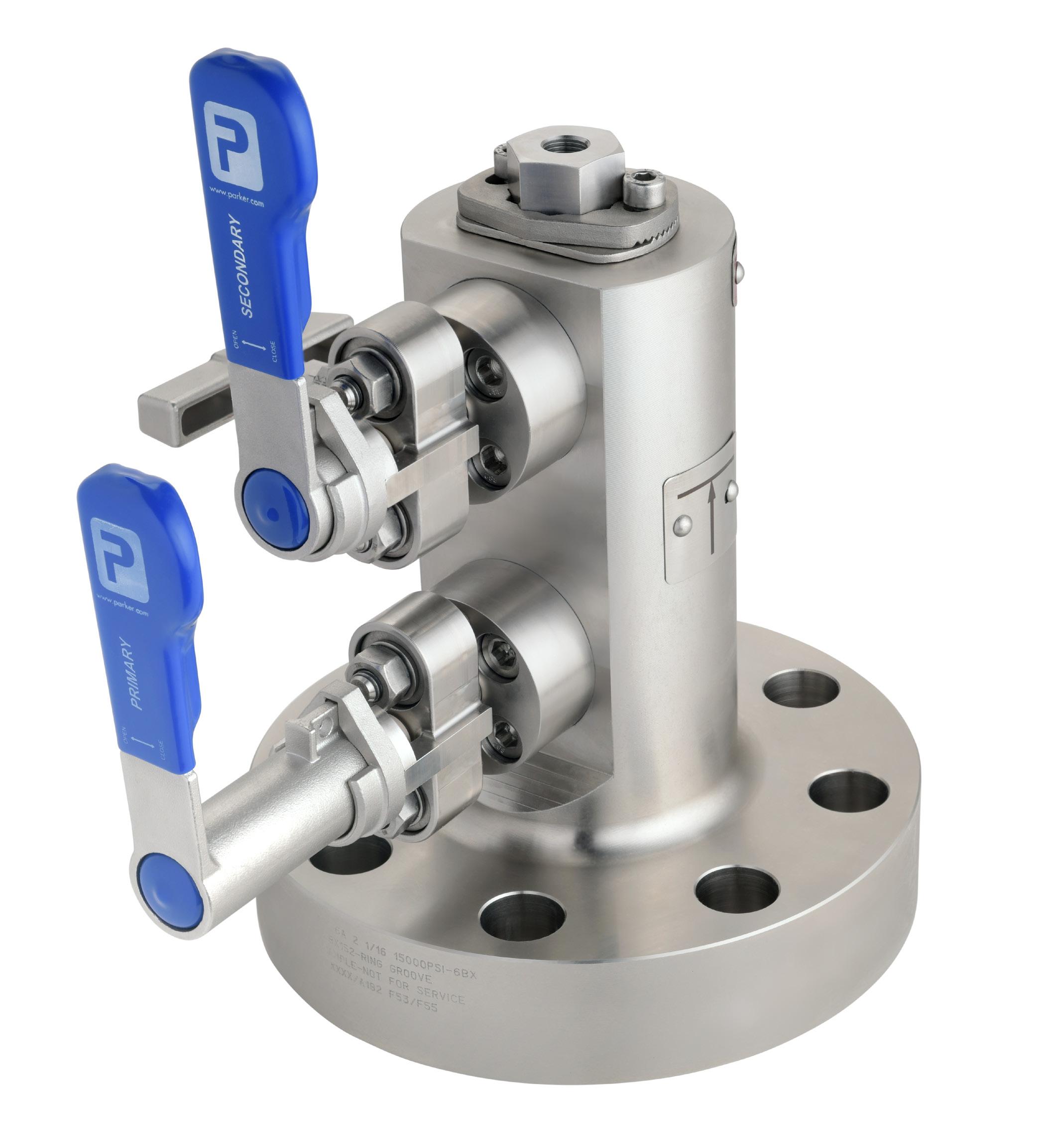
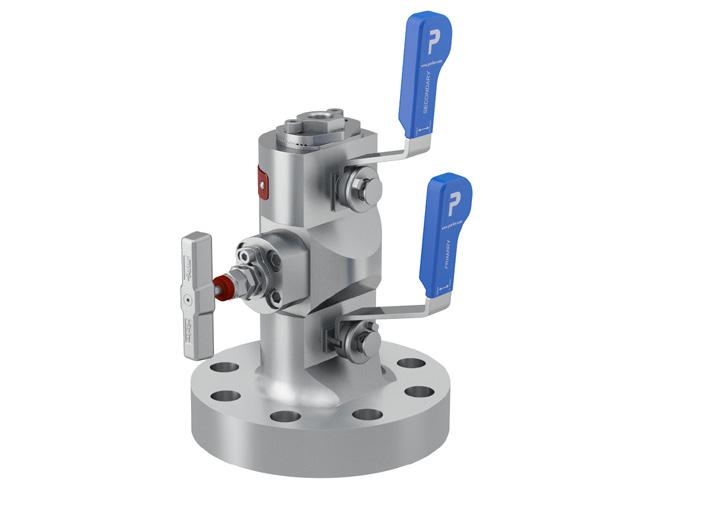
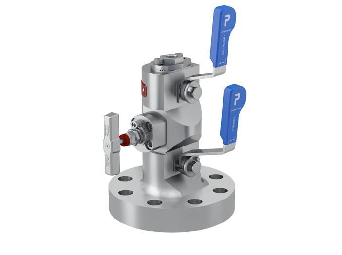
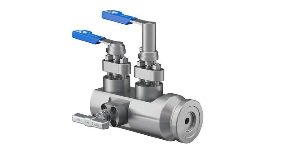
Ball Valve Design - 5K and 10K
Overview
Parker’s uni directional quarter turn ball valve antistatic design is based on the Hi-Pro® ball valves series which has been used in the field on many services over a twenty-year time span. Just like the Hi-Pro® , the API 6A design incorporates slotted seats. This gives inherent cavity relief preventing over pressure occurring within the ball/seat cavity when the valve is in the closed position. The stem itself is a blow-out proof design. The valves are a straight through bore that helps to prevent “plugging” of the bore.
For pressure and temperature chart please see page 24
6
E G H I
B A C
D F
1 2 3 4 5 6 7 8 9 10 11 12 13
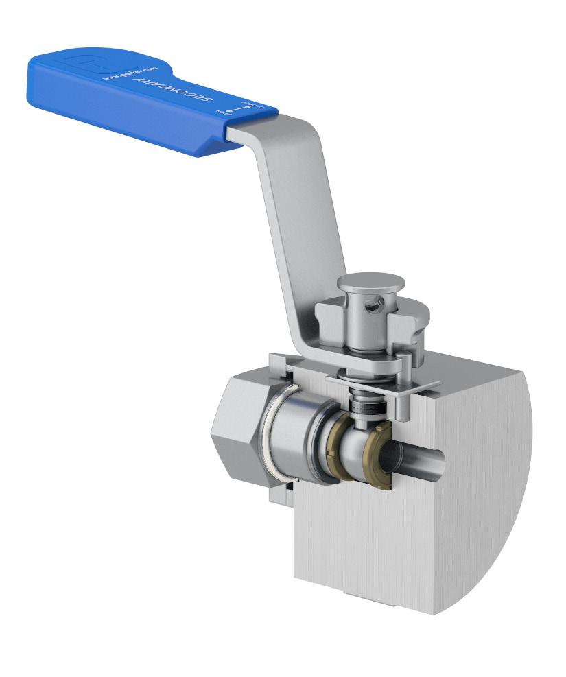
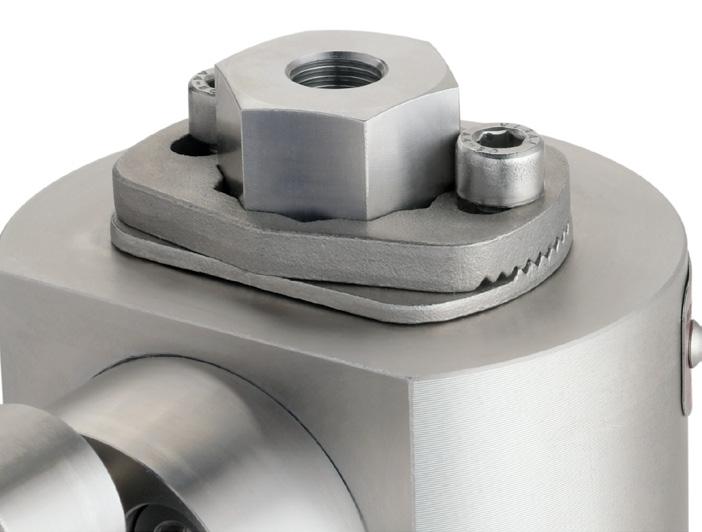
Reference Feature Benefit Value A Identification of primary and secondary valves Removes possibility of operating error Safety B Ergonomic vinyl sleeve Easy to grip Ease of operation C Handle locking mechanism Enables the valve to be locked in either the open or closed position Safety D EEMUA 182 Locking Nut Ensures packing integrity if handle needs to be removed Performance and reliability E Torque plate Reduces operational torque on packing Ease of operation F Anti blow out stem Prevents stem blow out Safety G Slotted seats Inherent cavity relief Safety H Environmental seal Preventing aggressive dirt and moisture Performance and reliability I Primary metallic atmospheric seal No elastomers, therefore no seal deterioration Performance and reliability 7 Reference Description Duplex Super Duplex 625 PSL 3/3G 1 Body A182-F51 A182-F53/F55 ASTM B564 Gr. N06625 YES 2 Ball A479-UNS S31803 A479-UNS S32750/S32760 ASTM B446 Gr. N06625 YES 3 Seats PEEK PEEK PEEK 4 End Adaptor A479-UNS S31803 A479-UNS S32750/S32760 ASTM B446 Gr. N06625 YES 5 Joint Seal 6mo ASTM B446 Gr. N06625 ASTM B446 Gr. N06625 6 Stem A479-UNS S31803 A479-UNS S32750/S32760 ASTM B446 Gr. N06625 YES 7 Packing Graphite Graphite Graphite 8 Ant-torque plate 316 St.Stl 316 St.Stl 316 St.Stl 9 Stop Pin 316 St.Stl 316 St.Stl 316 St.Stl 10 Thrust Bush 316 St.Stl 316 St.Stl 316 St.Stl 11 Spring Washer X12CrNi17 7 (DIN 1.4310) X12CrNi17 7 (DIN 1.4310) X12CrNi17 7 (DIN 1.4310) 12 Spindle Nuts A4. St.Stl A4. St.Stl A4. St.Stl 13 Handle 316 St.Stl 316 St.Stl 316 St.Stl Bill of Materials Notes: NPT & Autoclave plugs/glands are not PSL3 tested as standard. Features, Benefits and Values
Ball Valve Design - 15K
Overview
In addition to the features mentioned for the 5,000 and 10,000 ball valve design, the stem packing is live loaded graphite. The live loading assists the packing to compensate for any wear during the service life of the valve. This in turn reduces the need for any maintenance and prolongs the up-time of the valve. The live loaded packing is compressed by an Outside Screw and Yoke design, commonly used in piping valves as it is both strong and reliable. The stem itself is a blow-out proof design.
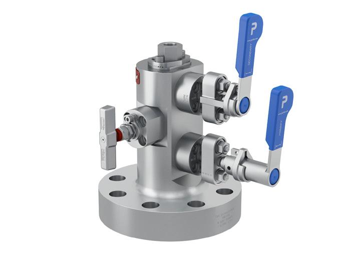
Tru-Loc® Mechanical Sealed End Connection
Designed specifically for Pro-Bloc end connection security. Extensive tests have proved that end connections locked with the Tru-Loc® end connector locking mechanism give 100% security and prevent end connector movement when disconnecting instruments or connectors. This ensures that the ball seat is securely positioned at all times.
D B E F
G C A 11 10 2 4 1 3 H 5 6 7 8 12 13 14 15 9 8 I
Reference Feature Benefit Value A Handle locking mechanism Enables the valve to be locked in either the open or closed position Safety B Bevel washers (coned disk spring) for live loading of packing Compensates for wear of the packing, preventing stem leakage Safety C Yoke (bridge) is manufactured from Super Duplex casting as standard API 6A material compliant Safety D Proprietary high pressure graphite packing with corrosion inhibitor Fire safe Safety E Bolted bonnet Removes mechanical hold threads from the process media Performance and reliability F Anti blow out stem Prevents stem blow out Safety G Primary metallic atmospheric seal No elastomers, therefore no seal deterioration Performance and reliability H Slotted seats Provides equalization of cavity pressure Performance and reliability I Vented ball Ensures body cavity relief is achieved Safety Reference Description Duplex Super Duplex 625 PSL 3/3G 1 Body A182-F51 A182-F53/F55 ASTM B564 Gr. N06625 YES 2 Ball A479-UNS S32750/S32760 A479-UNS S32750/S32760 Alloy 718 API YES 3 Seats PAI PAI PAI 4 End Adaptor A479-UNS S31803 A479-UNS S32750/S32760 ASTM B446 Gr. N06625 YES 5 Joint Seal 6mo Alloy 625 Alloy 625 6 Stem A479-UNS S32750/S32760 A479-UNS S32750/S32760 Alloy 718 API YES 7 Bonnet A479-UNS S31803 A479-UNS S32750/S32760 ASTM B446 Gr. N06625 YES 8 Packing Graphite Graphite Graphite 9 Studs ASTM A453 GR.660A ASTM A453 GR.660A ASTM A453 GR.660A 10 Thrust Bush A479-UNS S31803 A479-UNS S32750/S32760 ASTM B446 Gr. N06625 11 OSY Bridge Super Duplex ASTM A995 Gr. 6A Super Duplex ASTM A995 Gr. 6A Super Duplex ASTM A995 Gr. 6A 12 Spring Washer X12CrNi17 7 (DIN 1.4310) X12CrNi17 7 (DIN 1.4310) X12CrNi17 7 (DIN 1.4310) 13 OSY Nuts ASTM A453 GR.660A ASTM A453 GR.660A ASTM A453 GR.660A 14 Spindle Nuts A4. St.Stl A4. St.Stl A4. St.Stl 15 Handle 316 St.Stl 316 St.Stl 316 St.Stl Bill of Materials Notes: NPT & Autoclave plugs/glands are not PSL3 tested as standard. Features, Benefits and Values 9
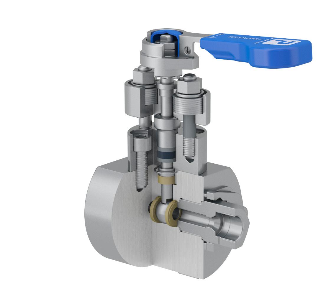
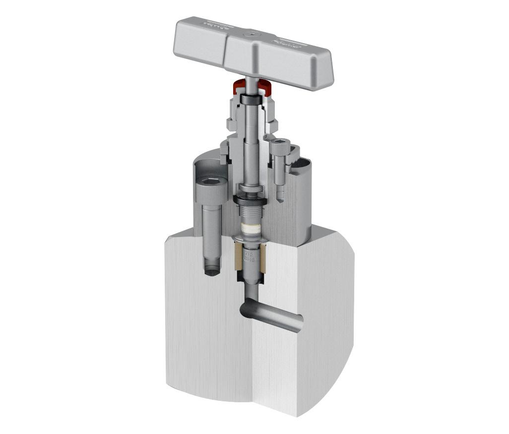
Needle Valve Design - 5K, 10K and 15K
Overview
The Parker heavy duty needle valve has been extensively used both offshore and onshore, including sour gas fields. The two piece stem ensures the tip does not rotate on closure ensuring a gas tight shut off with no opportunity for seat damage or galling. The packing itself is below the stem threads protecting them from the media and ensuring the thread lubricant is not “washed out”.
The stem packing is a combination of PTFE and high purity graphite which is live loaded to reduce the need for packing adjustment. A protective cap is secured above the threads to prevent ingress of moisture or dirt. The valve has a bolted bonnet construction which is stronger, safer and more reliable than a screwed bonnet design. The sealing between bonnet and head unit is a metal seal for increased durability and increased operating life. The handle is held firmly into the top of the stem with an anti-vibration design to prevent the handle becoming loose in operation.
10
A
C E G H F B 1 2 3 4 5 7 6 8 D 9 10 11 12 12 13 15 14
11 Reference Feature Benefit Value A Protective cap Secured above the threads to prevent ingress of moisture or dirt Durability B Fire safe / environmental seal Fire safe Safety C Bolted bonnet Removes mechanical hold threads from the process media Performance and reliability D Anti blow out stem Prevents stem blow out Safety E Two piece stem Lower stem non rotational for increased cycle life and improved seal ability, preventing damage to seat Safety, performance and reliability F Bevel washers (coned disk spring) for live loading of packing Compensates for wear of the packing, preventing stem leakage and compensates for temperature cycling Performance and reliability G PEEK guide bush Aides with centering of tip Performance H Primary metallic atmospheric seal No elastomers, therefore no seal deterioration Performance and reliability Reference Description Duplex Super Duplex 625 PSL 3/3G 1 Body A182-F51 A182-F53/F55 ASTM B564 Gr. N06625 YES 2 Lower Stem A479-UNS S32750/ S32760 ASTM B446 Gr. N06625 Alloy 718 API YES 3 Stem Guide PEEK PEEK PEEK 4 Joint Seal 6mo ASTM B446 Gr. N06625 ASTM B446 Gr. N06625 5 Packing P.T.F.E P.T.F.E P.T.F.E 6 Thrust Bush A479-UNS S31803 A479-UNS S32750/S32760 ASTM B446 Gr. N06625 7 Bonnet Studs ASTM A453 GR.660A ASTM A453 GR.660A ASTM A453 GR.660A 8 Spring Washer X12CrNi17 7 (DIN 1.4310) X12CrNi17 7 (DIN 1.4310) X12CrNi17 7 (DIN 1.4310) 9 Firesafe Packing Graphite Graphite Graphite 10 Gland Adjuster A479-UNS S31803 A479-UNS S32750/S32760 ASTM B446 Gr.
YES 11 Upper Stem A479-UNS S31803 A479-UNS S32750/S32760 ASTM B446 Gr.
YES 12 Bolted Bonnet A479-UNS S31803 A479-UNS
ASTM
Gr.
YES 13 Firesafe Gland A479-UNS
A479-UNS
ASTM
YES 14 Handle 316 St.Stl 316 St.Stl 316
15 Handle Screw 316 St.Stl 316 St.Stl 316 St.Stl Bill of Materials Notes: NPT & Autoclave plugs/glands are not PSL3 tested as standard. Features, Benefits and Values
N06625
N06625
S32750/S32760
B446
N06625
S31803
S32750/S32760
B446 Gr. N06625
St.Stl
1/6” 33
13/16” 29 10,000
(6BX) 10K 2 - 1/6” 33 2 - 9/16” 41
2 - 1/6” 33
13/16”
1/6” 33
9/16” 41
1/6” 33
9/16” 41
Series API Pro-Bloc APB Process / Instrument Connection(1) Material Flange Size Face Style Flange Class Duplex E
-
Ring Type Joint T
PSI
PSI
Super Duplex F
PSI
PSI
625 M 2
5,000 PSI
5K 1
10,000 PSI (6BX) 10K 2
2
Ball Valve Bore Size 10 mm Y Valve Handle Options Padlock Handle Locking Primary Ball Valve Only L1 Padlock Handle Locking Secondary Ball Valve L2 Padlock Handle Locking Primary and Secondary Ball Valve L12 Flanged Ball Valves Part Number Builder 5K and 10K APB Arrangement Block Bleed Block 1st Isolate: Ball Vent: Needle 2nd Isolate: Ball 00 Block and Bleed 1st Isolate: Ball Vent: Needle 30 00 9C L1 Style Flange x Screw 1 Flange x Flange 2 1 E33T10K Outlet / Vent Connection 1/2” FNPT9/16” MP Autoclave 9C 3/8” MP Autoclave 6C FN Condition Fire Safe F NACE N Fire Safe & NACE FN Y • PEEK seat as standard • If 1/2” NPT (F) outlet is selected then vent connection is 1/2”NPT (F) only. No connection designator required Notes: Process Process Outlet Outlet Vent Vent 12
2
5,000
(6B) 5K 1 -
5,000
(6B) 5K 1 -
29 10,000
(6BX) 10K 2 -
2 -
- 1/6” 33
(6B)
- 13/16” 29
-
-
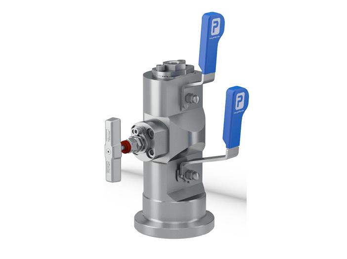
Flanged Ball Valves
Example Part Numbers 5K and 10K
Example 1 - APBY100E33T5KFN
Pro-Bloc 10mm Bore Flange x Screw Block-Bleed-Block (Ball-Needle-Ball)
Duplex A182-F51
Process Flange: API 6A - 2 1/16” x 5,000 PSI 6B M.C.W.P: 5,000 psig [344 barg]
Outlet/Vent connections: 1/2-14 NPT (FEM)
Firesafe to API 6FA/API 607
NACE MR0175 compliance
Example 2 - APBY230F33T10K9CL1FN
Pro-Bloc 10mm Bore Flange x Flange Block-Bleed (Ball-Needle)
Super Duplex A182-F53/F55
Process Flange: API 6A - 2 1/16” x 10,000 PSI 6BX
Instrument Flange: API 6A - 2 1/16” x 10,000 PSI 6BX M.C.W.P: 10,000 psig [689 barg]
Vent connections: 9/16” Medium Pressure Autoclave
Valve locking – Primary ball valve Firesafe to API 6FA/API 607 NACE MR0175 compliance
Example 3 - APBY100F33T10K9CL12FN
Pro-Bloc 10mm Bore Flange x Screw Block-Bleed-Block (Ball-Needle-Ball)
Super Duplex A182-F53/F55
Process Flange: API 6A - 2 1/16” x 10,000 PSI 6BX M.C.W.P: 10,000 psig [689 barg]
Outlet connection: 9/16” Medium Pressure Autoclave Vent connection: 1/2-14 NPT (FEM)
Valve locking – Primary & secondary ball valves Firesafe to API 6FA/API 607
NACE MR0175 compliance
Example 4 - APBY100M33T10K9C6CL12FN
Pro-Bloc 10mm Bore Flange x Screw Block-Bleed-Block (Ball-Needle-Ball)
Alloy 625 ASTM B564 Gr. N06625 Process Flange: API 6A - 2 1/16” x 10,000 PSI 6BX M.C.W.P: 10,000 psig [689 barg]
Outlet connection: 9/16” Medium Pressure Autoclave Vent connection: 3/8” Medium Pressure Autoclave Valve locking – Primary & secondary ball valves Firesafe to API 6FA/API 607
NACE MR0175 compliance
13
Series API Pro-Bloc APB Ball Valve Bore Size 10 mm Y Flanged Ball Valves Part Number Builder 15K APB 1 Arrangement Block Bleed Block 1st Isolate: Ball Vent: Needle 2nd Isolate: Ball 00 Block and Bleed 1st Isolate: Ball Vent: Needle 30 00 9C Style Flange x Screw 1 Flange x Flange 2 Y F29T15K Outlet / Vent Connection 9/16” MP Autoclave 9C 3/8” MP Autoclave 6C Valve Handle Options Padlock Handle Locking Primary Ball Valve Only L1 Padlock Handle Locking Secondary Ball Valve L2 Padlock Handle Locking Primary and Secondary Ball Valve L12 L1 FN 14 Process Process Outlet Outlet Vent Vent Condition Fire Safe F NACE N Fire Safe & NACE FN Process / Instrument Connection Material Flange Size Face Style Flange Class Super Duplex F 1 - 13/16” 29 Ring Type Joint T 15,000 PSI (6BX) 15K 2 - 1/6” 33
Flanged Ball Valves
Example Part Numbers15K
Example 1 - APBY100F29T15K9C9CL12FN
Pro-Bloc 10mm Bore Flange x Screw Block-Bleed-Block (Ball-Needle-Ball)
Super Duplex A182-F53/F55
Process Flange: API 6A - 1 13/16” x 15,000 PSI 6BX
M.C.W.P: 15,000 psig [1034 barg]
Outlet/Vent connection: 9/16” Medium Pressure Autoclave
Valve locking – Primary & secondary ball valves Firesafe to API 6FA/API 607 NACE MR0175 compliance
Example 2 - APBY230F29T15K9CL12FN
Pro-Bloc 10mm Bore Flange x Flange Block-Bleed (Ball-Needle)
Super Duplex A182-F53/F55
Process Flange: API 6A - 1 13/16” x 15,000 PSI 6BX Instrument Flange: API 6A - 1 13/16” x 15,000 PSI 6BX
M.C.W.P: 15,000 psig [1034 barg]
Vent connection: 9/16” Medium Pressure Autoclave Valve locking – Primary & secondary ball valves Firesafe to API 6FA/API 607 NACE MR0175 compliance
Example 3 - APBY130F29T15K9C6CL1FN
Pro-Bloc 10mm Bore Flange x Screw Block-Bleed (Ball-Needle)
Super Duplex A182-F53/F55
Process Flange: API 6A - 1 13/16” x 15,000 PSI 6BX M.C.W.P: 15,000 psig [1034 barg]
Outlet connection: 9/16” Medium Pressure Autoclave Vent connection: 3/8” Medium Pressure Autoclave Valve locking – Primary ball valve Firesafe to API 6FA/API 607 NACE MR0175 compliance
15
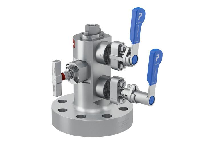
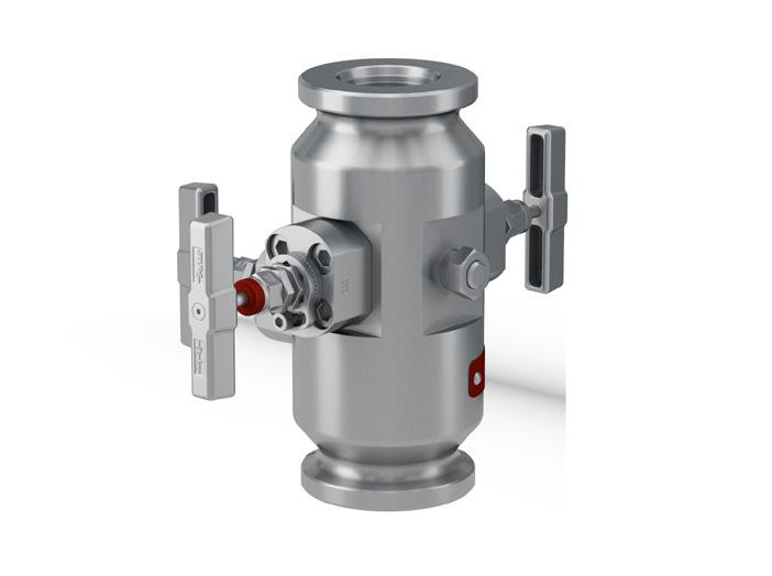
Series API Pro-Bloc APB Process / Instrument Connection(1) *Clamp & Bolt Material Material Hub Size AISI 4140 Clamp & A320-L7 Bolting Duplex E 1 - 1/2” 24 Hub G Seal 11 11 1 - 1/2” 24 Seal 14 14 2” 32 Seal 11 11 2” 32 Seal 13 13 2” 32 Seal 14 14 2” Seal 16 16 2” 32 Heavy Duty Hub B Seal 14 14 AISI 4140 Clamp & A320-L7 Bolting Super Duplex F 1 - 1/2” 24 Hub G Seal 11 11 1 - 1/2” 24 Seal 11 14 2” 32 Seal 11 11 2” 32 Seal 13 13 2” 32 Seal 14 14 2” 32 Seal 16 16 2” 32 Seal 20 20 2” 32 Heavy Duty Hub B Seal 14 14 A182-F304 Clamp & A320-B8 Bolting 625 M 1 - 1/2” 24 Hub G Seal 11 11 2” 32 Seal 11 11 2” 32 Seal 13 13 2” 32 Heavy Duty Hub B Seal 14 14 Ball Valve Bore Size 10 mm Y Valve Handle Options Padlock Handle Locking Primary Ball Valve Only L1 Padlock Handle Locking Secondary Ball Valve L2 Padlock Handle Locking Primary and Secondary Ball Valve L12 Grayloc® Hub Ball Valves Part Number Builder 10K APB Y Arrangement Block Bleed Block 1st Isolate: Ball Vent: Needle 2nd Isolate: Ball 00 Block and Bleed1 1st Isolate: Ball Vent: Needle 30 00 9C L1 Style Hub x Screw 1 Hub x Hub 2 1 E24G11 Outlet / Vent Connection2 1/2” FNPT9/16” MP Autoclave 9C 3/8” MP Autoclave 6C FN Pressure Rating 10K PSI 10K 10K Process Process Outlet Outlet Vent Vent Condition Fire Safe F NACE N Fire Safe & NACE FN 1. The hub x hub outlet end will also include a female 9/16 MP Autoclave Connection • If 1/2” NPT (F) outlet is selected then vent connection is 1/2”NPT (F) only. No connection designator required • Hub/Seal size selection shown is based on the overall combined pressure capability of base material with the clamp and bolt materials as listed * Hub ended valves are NOT supplied with seals, clamps and bolts as standard Notes: 16 2. The female medium pressure vent is supplied with a plug.
Grayloc® Hub Ball Valves
Example Part Numbers 10K
Example 1 - APBY100F32G1410K9C6CL12FN
Pro-Bloc 10mm Bore
Hub x Screw
Block-Bleed-Block (Ball-Needle-Ball)
Super Duplex A182-F53/F55
Process hub: 2” GR 14
Outlet connection: 9/16” Medium Pressure Autoclave Vent connection: 3/8” Medium Pressure Autoclave M.C.W.P: 10,000 psig [689 barg]
Valve locking – Primary & secondary ball valves Firesafe to API 6FA/API 607 NACE MR0175 compliance
Example 2 - APBY100M24G1110K9C9CL12FN
Pro-Bloc 10mm Bore
Hub x Screw
Block-Bleed-Block (Ball-Needle-Ball)
Alloy 625
Process hub: 1 1/2” GR 11 Outlet connection: 9/16” Medium Pressure Autoclave Vent connection: 9/16” Medium Pressure Autoclave M.C.W.P: 10,000 psig [689 barg]
Valve locking – Primary & secondary ball valves Firesafe to API 6FA/API 607 NACE MR0175 compliance
Example 3 – APBY200F32G1410K6CL12FN
Pro-Bloc 10mm Bore Hub x Hub
Block-Bleed-Block (Ball-Needle-Ball)
Super Duplex A182-F53/F55
Process hub: 2” GR 14
Outlet connection: 2” GR 14
Vent connection: 3/8” Medium Pressure Autoclave M.C.W.P: 10,000 psig [689 barg]
Valve locking – Primary & secondary ball valves Firesafe to API 6FA/API 607 NACE MR0175 compliance
17
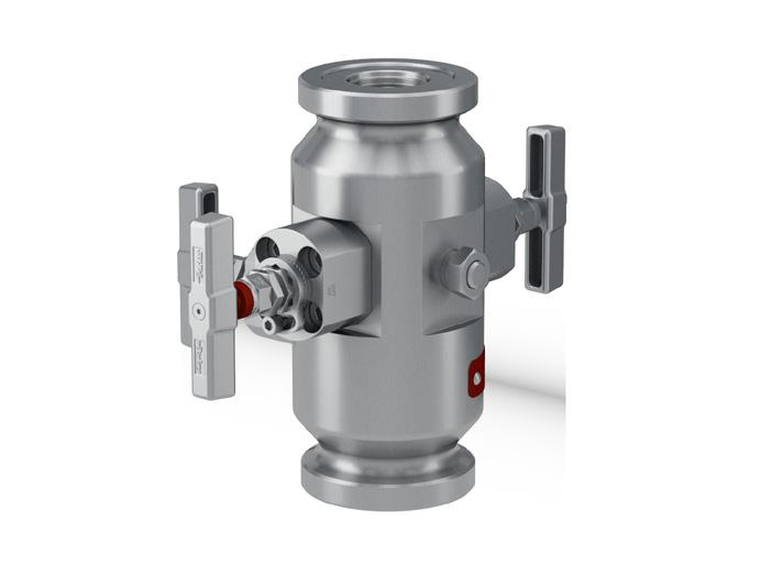
Grayloc® Hub Ball Valves Part Number Builder 15K Outlet / Vent Connection2 9/16” MP Autoclave 9C 3/8” MP Autoclave 6C Series API Pro-Bloc APB Ball Valve Bore Size 10 mm Y Valve Handle Options Padlock Handle Locking Primary Ball Valve Only L1 Padlock Handle Locking Secondary Ball Valve L2 Padlock Handle Locking Primary and Secondary Ball Valve L12 APB Y Arrangement Block Bleed Block 1st Isolate: Ball Vent: Needle 2nd Isolate: Ball 00 Block and Bleed1 1st Isolate: Ball Vent: Needle 30 00 9C L1 Style Hub x Screw 1 Hub x Hub 2 1 E24G11 FN Pressure Rating 10K PSI 15K 15K 18 Process Process Outlet Outlet Vent Vent Condition Fire Safe F NACE N Fire Safe & NACE FN 1. The hub x hub outlet end will also include a female 9/16 MP Autoclave Connection Process / Instrument Connection *Clamp & Bolt Material Material Hub Size AISI 4140 Clamp & A320-L7 Bolting Duplex E 1 - 1/2” 24 Hub G Seal 11 11 2” 32 Seal 11 11 2” 32 Seal 13 13 2” 32 Seal 14 14 2” 32 Heavy Duty Hub B Seal 14 14 AISI 4140 Clamp & A320-L7 Bolting Super Duplex F 1 - 1/2” 24 Hub G Seal 11 11 2” 32 Seal 14 14 2” 32 Seal 13 13 2” 32 Seal 14 14 2” 32 Seal 16 16 2” 32 Heavy Duty Hub B Seal 14 14 A182-F304 Clamp & A320-B8 Bolting 625 M 1 - 1/2” 24 Hub G Seal 11 11 2” 32 Seal 11 11 2” 32 Heavy Duty Hub B Seal 14 14 • Hub/Seal size selection shown is based on the overall combined pressure capability of base material with the clamp and bolt materials as listed * Hub ended valves are NOT supplied with seals, clamps and bolts as standard Notes: 2. The female medium pressure vent is supplied with a plug.
Grayloc® Hub Ball Valves
Example Part Numbers 15K
Example 1 - APBY100E32G1415K9C6CL12FN
Pro-Bloc 10mm Bore Hub x Screw
Block-Bleed-Block (Ball-Needle-Ball)
Duplex A182-F51
Process hub: 2” GR 14
Outlet connection: 9/16” Medium Pressure Autoclave Vent connection: 3/8” Medium Pressure Autoclave M.C.W.P: 15,000 psig [1034 barg]
Valve locking – Primary & secondary ball valves Firesafe to API 6FA/API 607 NACE MR0175 compliance
Example 2 – APBY230M32B1415K9CL1FN
Pro-Bloc 10mm Bore Hub x Screw
Block-Bleed (Ball-Needle)
Alloy 625 Process hub: 2” B14 Outlet hub: 2” B14 Vent connection: 9/16” Medium Pressure Autoclave M.C.W.P: 15,000 psig [1034 barg]
Valve locking – Primary ball valve Firesafe to API 6FA/API 607 NACE MR0175 compliance
19
Series Hub to Hub APB Process / Instrument Connection *Clamp & Bolt Material Material Hub Size AISI 4140 Clamp & A320-L7 Bolting Duplex E 1 - 1/2” 24 Hub G Seal 11 11 1 - 1/2” 24 Seal 14 14 2” 32 Seal 11 11 2” 32 Seal 13 13 2” 32 Seal 14 14 2” 32 Seal 16 16 2” 32 Heavy Duty Hub B Seal 14 14 AISI 4140 Clamp & A320-L7 Bolting Super Duplex F 1 - 1/2” 24 Hub G Seal 11 11 1 - 1/2” 24 Seal 11 14 2” 32 Seal 11 11 2” 32 Seal 13 13 2” 32 Seal 14 14 2” 32 Seal 16 16 2” 32 Seal 20 20 2” 32 Heavy Duty Hub B Seal 14 14 A182-F304 Clamp & A320-B8 Bolting 625 M 1 - 1/2” 24 Hub G Seal 11 11 2” 32 Seal 11 11 2” 32 Seal 13 13 2” 32 Heavy Duty Hub B Seal 14 14 Grayloc® Hub Needle Valves Part Number Builder 10K APB Arrangement1 Block Bleed Block 1st Isolate: Needle Vent: Needle 2nd Isolate: Needle NNN Block and Bleed 1st Isolate: Needle Vent: Needle NN NN Style( Hub x Screw 1 Hub x Hub 2 1 E24G11 Outlet / Vent Connection2 1/2” FNPT 9/16” MP Autoclave 9C 3/8” MP Autoclave 6C FN Pressure Rating 10K PSI 10K 10K 9C 1. The hub x hub outlet end will also include a female 9/16 MP Autoclave Connection • Needle Valve bore size 8mm • Hub/Seal size selection shown is based on the overall combined pressure capability of base material with the clamp and bolt materials as listed * Hub ended valves are NOT supplied with seals, clamps and bolts as standard Notes: 20 Process Process Outlet Outlet Vent Vent Condition Fire Safe F NACE N Fire Safe & NACE FN 2. The female medium pressure vent is supplied with a plug.
Grayloc® Hub Needle Valves
Example Part Numbers 10K
Example 1 – APB2NNNF24G1110K9CFN
Pro-Bloc 8m Bore Hub x Hub
Block-Bleed-Block (Needle-Needle-Needle)
Super Duplex A182-F53/F55
Process hub: 1 1/2” GR 11
Outlet hub: 1 1/2” GR 11
M.C.W.P: 10,000 psig [689 barg]
Vent connection: 9/16” Medium Pressure Autoclave Firesafe to API 6FA/API 607 NACE MR0175 compliance
Example 2 – APB1NNE32G1310KFN
Pro-Bloc 8m Bore Hub x Screw
Block-Bleed (Needle-Needle)
Duplex A182-F51
Process hub: 2” GR 13
M.C.W.P: 10,000 psig [689 barg]
Outlet/Vent: 1/2” NPT (FEM)
Firesafe to API 6FA/API 607 NACE MR0175 compliance
21
Grayloc® Hub Needle Valves Part Number Builder 15K Series Hub to Hub APB Process / Instrument Connection *Clamp & Bolt Material Material Hub Size AISI 4140 Clamp & A320-L7 Bolting Duplex E 1 - 1/2” 24 Hub G Seal 11 11 2” 32 Seal 11 11 2” 32 Seal 13 13 2” 32 Seal 14 14 2” 32 Heavy Duty Hub B Seal 14 14 AISI 4140 Clamp & A320-L7 Bolting Super Duplex F 1 - 1/2” 24 Hub G Seal 11 11 2” 32 Seal 11 11 2” 32 Seal 13 13 2” 32 Seal 14 14 2” 32 Seal 16 16 2” 32 Seal 20 20 2” 32 Heavy Duty Hub B Seal 14 14 A182-F304 Clamp & A320-B8 Bolting 625 M 1 - 1/2” 24 Hub G Seal 11 11 2” 32 Seal 11 11 2” 32 Heavy Duty Hub B Seal 14 14 APB Arrangement1 Block Bleed Block 1st Isolate: Needle Vent: Needle 2nd Isolate: Needle NNN Block and Bleed 1st Isolate: Needle Vent: Needle NN NN Style(1) Hub x Screw 1 Hub x Hub 2 2 F32B14 Outlet / Vent Connection2 9/16” MP Autoclave 9C 3/8” MP Autoclave 6C FN Pressure Rating 10K PSI 15K 15K 9C 1. The hub x hub outlet end will also include a female 9/16 MP Autoclave Connection • Needle Valve bore size 8mm • Hub/Seal size selection shown is based on the overall combined pressure capability of base material with the clamp and bolt materials as listed * Hub ended valves are NOT supplied with seals, clamps and bolts as standard Notes: Process Process Outlet Outlet Vent Vent Condition Fire Safe F NACE N Fire Safe & NACE FN 22 2. The female medium pressure vent is supplied with a plug.
Grayloc® Hub Needle Valves
Example Part Numbers 15K
Example 1 – APB2NNNF32B1415K9CFN
Pro-Bloc 8m Bore
Hub x Hub
Block-Bleed-Block (Needle-Needle-Needle)
Super Duplex A182-F53/F55
Process hub: 2” B14
Outlet hub: 2” B14
M.C.W.P: 15,000 psig [1034 barg]
Vent connection: 9/16” Medium Pressure Autoclave Firesafe to API 6FA/API 607
NACE MR0175 compliance
Example 2 – APB1NNE32G1415K9C9CFN
Pro-Bloc 8m Bore
Hub x Screw
Block-Bleed (Needle-Needle)
Duplex A182-F51
Process hub: 2” GR 14
Outlet connection: 9/16” Medium Pressure Autoclave
Vent connection: 9/16” Medium Pressure Autoclave M.C.W.P: 15,000 psig [1034 barg]
Firesafe to API 6FA/API 607
NACE MR0175 compliance
23
Commonly used terms when conducting business with Parker
Acronym Title Description
API American Petroleum Institute
The American Petroleum Institute (API) is the largest U.S. trade association for the oil and natural gas industry.
PSL Product Specification Level Material compliance and factory acceptance testing
NDE Non Destructive Examination
Volumetric and surface non destructive testing
FAT Factory Acceptance Test Pressure testing
Serialization
Tru-Loc®
An assignment of a unique code to individual parts and / or pieces of equipment to maintain records
Patented locking mechanism from Parker Hannifin Corporation
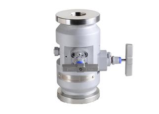
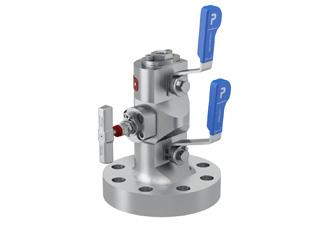
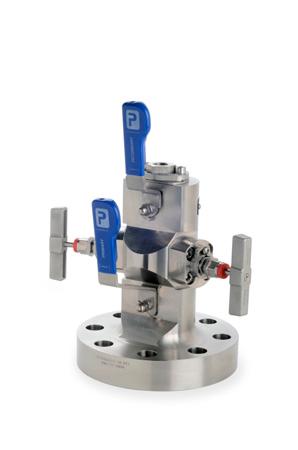
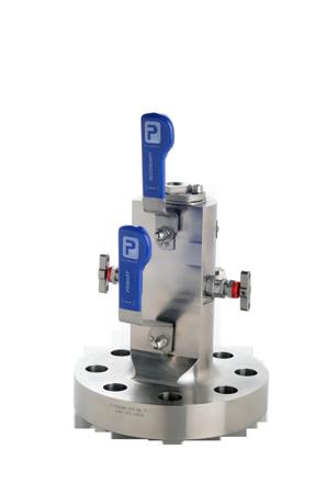
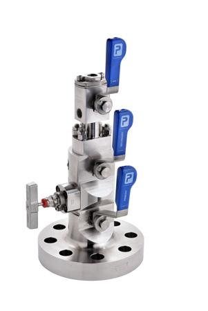
Parker’s API valves have been designed in partnership with many of the world’s leading energy companies. Pictured here, are just a few of the designs that we have innovated for projects around the world.

24
SEAT 15K
PAI
PEEK SEAT 10K PEEK SEAT 5K
Pressure
TEMP CLASS: P/V (-29 C TO 121 C)PEEK 10K / PAI 15K TEMPERATURE - CELSIUS °C (FAHRENHEIT °F) Ball Valve
/ Temperature Chart
Duplex
Close Shape Flanged Design
Hubbed Design
ASTM A182 Grade F51 NORSOK M650/M630 NACE MR0175 PSL3
ASTM A182 Grade F51 NORSOK M650/M630 NACE MR0175 PSL3
Close Shape Flanged Design
Hubbed Design
Trims such as Bonnets, end and
ASTM A182 Grades F53/F55 NACE MR0175 PSL3
ASTM A182 Grades F53/F55 NORSOK M650/M630 NACE MR0175 PSL3
A479/A276 UNS S31803 NORSOK M650/M630 NACE MR0175 PSL3 Super
connections ASTM A479/A276 UNS S32750/ S32760 NORSOK M650/M630 NACE MR0175 PSL3
ASTM A995 Grade 6A – UNS J93380 NACE MR0175 PSL3
Close Shape Flanged Design
Hubbed Design
Trims such as Bonnets, end and
ASTM B564 Grade UNS N06625 NACE MR0175 PSL3
ASTM B564 Grade UNS N06625 NACE MR0175 PSL3
connections ASTM B564 Grade UNS N06625 NACE MR0175 PSL3
3/3G
3/3G
25 Typical Raw Material Specifications
Product Industry Codes NORSOK NACE API Product Specification Level
Material
Trims such as Bonnets, end and outlet connections ASTM
Duplex
outlet
15K Ball Valve OSY Bridge
Alloy 625
outlet
end
outlet connections
API 6A - Quality control for bodies, bonnets, end and outlet connections - PSL 3/3G - Parker Compliance API Product Specification Level API Sub-Clause Additional Industry Codes
Alloy 718 Trims such as Bonnets,
and
API 6A UNS N07718 NACE MR0175 PSL3
Dimensional inspection
Ferritoscope: On request to Parker standard NORSOK M630 Additional testing includes*: Corrosion testing Micrographic examination
Ferrite counting
* (Duplex and Super Duplex materials only)
API 6A - Quality control requirements for regular and Venturi bore valves - PSL3/3G - Parker Compliance Product Specification Level Parker Comments Factory Acceptance testing: PSL3 PSL 3G Hydrostatic test (extended) Body 7.4.9.5.4 7.4.9.5.4 Seat 7.4.9.5.6 7.4.9.5.6 Gas test Body - 7.4.9.57 Seat - 7.4.9.5.8 Traceability 7.4.9.2.2 b) 7.4.9.2.2 b) Providing HCT 3.1B is selected Serialization 7.4.9.2.1 b) 7.4.9.2.1 b) Each tested assembly will have serial number against works order no.
PSL3/3G material testing includes: Tensile testing PSL
7.4.2.2.1 ASTM A370 Impact testing PSL
7.4.2.3.2 ASTM A370 PSL3/3G NDE includes:
to Parker standard Traceability PSL 3/3G 7.4.2.3.5 Chemical analysis PSL 3/3G 7.4.2.3.6 ASTM A388 Volumetric NDE PSL 3/3G 7.4.2.3.15 ASTM E165 / ASTM E709 Surface NDE PSL 3/3G 7.4.2.3.8 Serialization PSL 3/3G 7.4.2.3.14
ASTM G48
ASTM A923
ASTM E562
Parker Worldwide
Europe, Middle East, Africa
AE – United Arab Emirates, Dubai Tel: +971 4 8127100 parker.me@parker.com
AT – Austria, Wiener Neustadt Tel: +43 (0)2622 23501-0 parker.austria@parker.com
AT – Eastern Europe, Wiener Neustadt Tel: +43 (0)2622 23501 900 parker.easteurope@parker.com
AZ – Azerbaijan, Baku Tel: +994 50 2233 458 parker.azerbaijan@parker.com
BE/LU – Belgium, Nivelles Tel: +32 (0)67 280 900 parker.belgium@parker.com
BG – Bulgaria, Sofia Tel: +359 2 980 1344 parker.bulgaria@parker.com
BY – Belarus, Minsk Tel: +48 (0)22 573 24 00 parker.poland@parker.com
CH – Switzerland, Etoy Tel: +41 (0)21 821 87 00 parker.switzerland@parker.com
CZ – Czech Republic, Klecany Tel: +420 284 083 111 parker.czechrepublic@parker.com
DE – Germany, Kaarst Tel: +49 (0)2131 4016 0 parker.germany@parker.com
DK – Denmark, Ballerup Tel: +45 43 56 04 00 parker.denmark@parker.com
ES – Spain, Madrid Tel: +34 902 330 001 parker.spain@parker.com
FI – Finland, Vantaa Tel: +358 (0)20 753 2500 parker.finland@parker.com
FR – France, Contamine s/Arve Tel: +33 (0)4 50 25 80 25 parker.france@parker.com
GR – Greece, Athens Tel: +30 210 933 6450 parker.greece@parker.com
HU – Hungary, Budaörs Tel: +36 23 885 470 parker.hungary@parker.com
IE – Ireland, Dublin Tel: +353 (0)1 466 6370 parker.ireland@parker.com
IT – Italy, Corsico (MI) Tel: +39 02 45 19 21 parker.italy@parker.com
KZ – Kazakhstan, Almaty Tel: +7 7273 561 000 parker.easteurope@parker.com
NL – The Netherlands, Oldenzaal Tel: +31 (0)541 585 000 parker.nl@parker.com
NO – Norway, Asker Tel: +47 66 75 34 00 parker.norway@parker.com
PL – Poland, Warsaw Tel: +48 (0)22 573 24 00 parker.poland@parker.com
PT – Portugal, Leca da Palmeira Tel: +351 22 999 7360 parker.portugal@parker.com
RO – Romania, Bucharest Tel: +40 21 252 1382 parker.romania@parker.com
RU – Russia, Moscow Tel: +7 495 645-2156 parker.russia@parker.com
SE – Sweden, Spånga Tel: +46 (0)8 59 79 50 00 parker.sweden@parker.com
SK – Slovakia, Banská Bystrica Tel: +421 484 162 252 parker.slovakia@parker.com
SL – Slovenia, Novo Mesto Tel: +386 7 337 6650 parker.slovenia@parker.com
TR – Turkey, Istanbul Tel: +90 216 4997081 parker.turkey@parker.com
UA – Ukraine, Kiev Tel: +48 (0)22 573 24 00 parker.poland@parker.com
UK – United Kingdom, Warwick Tel: +44 (0)1926 317 878 parker.uk@parker.com
Parker Hannifin Manufacturing Ltd
Instrumentation Products Division Europe
Riverside Road
Pottington Business Park Barnstaple, Devon, EX31 1NP
United Kingdom
Tel.: +44 (0) 1271 313131 Fax: +44 (0) 1271 373636 www.parker.com/ptoi
ZA – South Africa, Kempton Park Tel: +27 (0)11 961 0700 parker.southafrica@parker.com
North America
CA – Canada, Milton, Ontario Tel: +1 905 693 3000
US – USA, Cleveland Tel: +1 216 896 3000
Asia Pacific
AU – Australia, Castle Hill Tel: +61 (0)2-9634 7777
CN – China, Shanghai Tel: +86 21 2899 5000
HK – Hong Kong Tel: +852 2428 8008
IN – India, Mumbai Tel: +91 22 6513 7081-85
JP – Japan, Tokyo Tel: +81 (0)3 6408 3901
KR – South Korea, Seoul Tel: +82 2 559 0400
MY – Malaysia, Shah Alam Tel: +60 3 7849 0800
NZ – New Zealand, Mt Wellington Tel: +64 9 574 1744
SG – Singapore Tel: +65 6887 6300
TH – Thailand, Bangkok Tel: +662 186 7000
TW – Taiwan, Taipei Tel: +886 2 2298 8987
South America
AR – Argentina, Buenos Aires Tel: +54 3327 44 4129
BR – Brazil, Sao Jose dos Campos Tel: +55 800 727 5374
CL – Chile, Santiago Tel: +56 2 623 1216
MX – Mexico, Toluca Tel: +52 72 2275 4200
European Product Information Centre
Free phone: 00 800 27 27 5374 (from AT, BE, CH, CZ, DE, DK, EE, EI, ES, FI, FR, IT, NL, NO, PL, RU, SE, SK, UK, ZA)
Parker Hannifin Corporation
Instrumentation Products Division 1005 A Cleaner Way Huntsville Alabama AL 35805
USA Tel: + 1 (256) 881-2040 Fax: + 1 (256) 881-5072 www.parker.com/ptoi
©
2018 Parker Hannifin Corporation. All rights reserved 4190-API
