Torqmotor™
Service Procedure
Effective: January 2017
TC, TS, TB, TE and TJ
Series
Low Speed, High Torque
HY13-1526-001-M1/US
Hydraulic Torqmotors™
HY13-1526-001-M1/US
Torqmotor™ Service Procedure
TC, TS, TB, TE and TJ Series
WARNING
FAILURE OR IMPROPER SELECTION OR IMPROPER USE OF THE PRODUCTS AND/OR SYSTEMS DESCRIBED HEREIN OR RELATED ITEMS CAN CAUSE DEATH, PERSONAL INJURY AND PROPERTY DAMAGE.
This document and other information from Parker Hannifn Corporation, its subsidiaries and authorized distributors provide product and/or system options for further investigation by users having technical expertise. It is important that you analyze all aspects of your application and review the information concerning the product or system in the current product catalog. Due to the variety of operating conditions and applications for these products or systems, the user, through its own analysis and testing, is solely responsible for making the fnal selection of the products and systems and assuring that all performance, safety and warning requirements of the application are met. The products described herein, including without limitation, product features, specifcations, designs, availability and pricing, are subject to change by Parker Hannifn Corporation and its subsidiaries at any time without notice.
Offer of Sale
The items described in this document are hereby offered for sale by Parker Hannifn Corporation, its subsidiaries or its authorized distributors. This offer and its acceptance are governed by the provisions stated in the “Offer of Sale”.
© Copyright 2017, 2015, 2007 - 2005, 2000, 1999, Parker Hannifn Corporation, All Rights Reserved
Parker Hannifin Corporation Hydraulic Pump/Motor Division Greeneville, TN 37745 US
2
Definitions
NOTE: A NOTE provides key information to make a procedure easier or quicker to complete.
CAUTION: A CAUTION refers to procedure that must be followed to avoid damaging the Torqmotor™ or other system components.
WARNING: A WARNING REFERS TO PROCEDURE THAT MUST BE FOLLOWED FOR THE SAFETY OF THE EQUIPMENT OPERATOR AND THE PERSON INSPECTING OR REPAIRING THE TORQMOTOR™.
Disclaimer
This Service Manual has been prepared by Parker Hannifn for reference and use by mechanics who have been trained to repair and service hydraulic motors and systems on commercial and non-commercial equipment applications. Parker Hannifn has exercised reasonable care and diligence to present accurate, clear and complete information and instructions regarding the techniques and tools required for maintaining, repairing and servicing the complete line of Parker TC, TS, TB, TE and TJ Torqmotor™ Units. However, despite the care and effort taken in preparing this general Service Manual, Parker makes no warranties that (a) the Service Manual or any explanations, illustrations, information, techniques or tools described herein are either accurate, complete or correct as applied to a specifc Torqmotor™ unit, or (b) any repairs or service of a particular Torqmotor™ unit will result in a properly functioning Torqmotor™ unit.
If inspection or testing reveals evidence of abnormal wear or damage to the Torqmotor™ unit or if you encounter circumstances not covered in the Manual, STOP – CONSULT THE EQUIPMENT MANUFACTURER’S SERVICE MANUAL AND WARRANTY. DO NOT TRY TO REPAIR OR SERVICE A TORQMOTOR™ UNIT WHICH HAS BEEN DAMAGED OR INCLUDES ANY PART THAT SHOWS EXCESSIVE WEAR UNLESS THE DAMAGED AND WORN PARTS ARE REPLACED WITH ORIGINAL PARKER REPLACEMENT AND SERVICE PARTS AND THE UNIT IS RESTORED TO PARKER SPECIFICATIONS FOR THE TORQMOTOR™ UNIT.
It is the responsibility of the mechanic performing the maintenance, repairs or service on a particular Torqmotor™ unit to (a) inspect the unit for abnormal wear and damage, (b) choose a repair procedure which will not endanger his/her safety, the safety of others, the equipment, or the safe operation of the Torqmotor™, and (c) fully inspect and test the Torqmotor™ unit and the hydraulic system to insure that the repair or service of the Torqmotor™ unit has been properly performed and that the Torqmotor™ and hydraulic system will function properly.
TC, TS, TB, TE and TJ
Parker Hannifin Corporation Hydraulic Pump/Motor Division Greeneville, TN 37745 US 3 Defnitions ................................................................................................................................................................3 Design Features .................................................................................................................................................4 - 5 Introduction .............................................................................................................................................................6 Troubleshooting Guide ............................................................................................................................................7 Troubleshooting Checklist .......................................................................................................................................8 Tools and Material Required for Servicing...............................................................................................................9 Bolt Torque ............................................................................................................................................................10 Exploded Assembly View .................................................................................................................................11-17 TC Service Parts List Chart ..............................................................................................................................18-19 TS Service Parts List Chart ...................................................................................................................................20 TB Service Parts List Chart ..............................................................................................................................21-22 TE Service Parts List Chart ..............................................................................................................................23-24 TJ Service Parts List Chart ...............................................................................................................................25-26 Disassembly & Inspection ................................................................................................................................27-34 Torqmotor™ Assembly .....................................................................................................................................35-44 Rotor Set Component Assembly Procedure (One Piece Stator) ...........................................................................45 Rotor Set Component Assembly Procedure (Two Piece Stator) ......................................................................46-47 Final Checks ..........................................................................................................................................................48 Hydraulic Fluids, Filtration, Oil Temperature .........................................................................................................48 Tips for Maintaining the System ............................................................................................................................49 Offer of Sale .................................................................................................................................Inside Back Cover
HY13-1526-001-M1/US Torqmotor™ Service Procedure
Series
Table of Contents
HY13-1526-001-M1/US
Torqmotor™ Design Features
Torqmotor™ Service Procedure
TC, TS, TB, TE and TJ Series
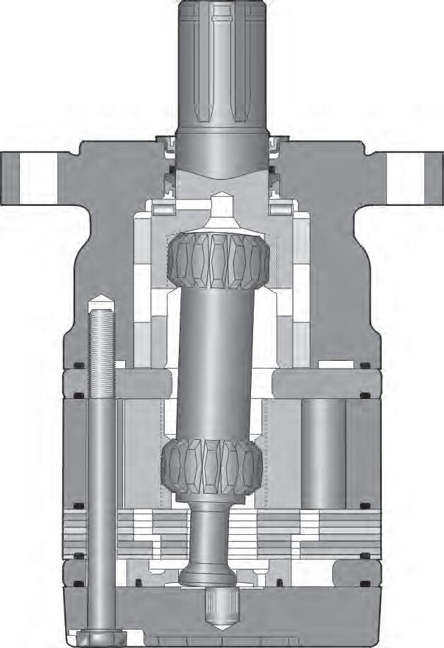
Torqmotor™ TB/TC Series features include:
• The roller vane rotor set design offers a low-friction, wear compensation which maximizes the useful performance life of the motor.
• Zero leak commutation valve provides greater, more consistent volumetric efficiency.
• Design fexibility - TB offers the widest selection of shaft options, displacements and mounting fanges in the industry.
• Patented 60-40 spline member arrangement transmits more torque with less weight.
• Full fow lubrication maximizes cooling and may provide up to 50% longer life than motors not having this feature.
• Higher pressure rating provide greater torque than competitive brands.
• Full interchangeability with other motors which are designed according to industry standards.
• Compatible with most hydraulic systems with regard to pressure, torque and speed.
• A unique high-pressure shaft seal that eliminates the need for case drains.
• Up to 18 horsepower output.
Torqmotor™ TE Series features include:
• Roller vanes to reduce friction and internal leakage and to maintain effciency.
• Zero leak commutation valve provides greater, more consistent volumetric efficiency.
• Wheel mount version available.
• More starting torque than competitive motors in applications where the shaft is side loaded. (Competitive brands require more pressure to start the motor.)
• A needle-roller mounted coupling shaft and steel-caged thrust bearing which can withstand 1000-pound thrust loads.
• Side load capacity is 1600 lbs. (727.3 kg) maximum at center of output shaft.
• A unique high-pressure shaft seal that eliminates the need for case drains, check valves and extra plumbing.
• Up to 23 horsepower output.
• Greater durability due to superior lubrication and minimum drive spline wear.
• Patented 60-40 spline member arrangement transmits more torque with less weight.
Parker Hannifin Corporation Hydraulic Pump/Motor Division Greeneville, TN 37745 US
4
RADIAL BEARING
NEEDLE
COUPLING SHAFT HIGH PRESSURE SEAL NEEDLE THRUST BEARING HOUSING DRIVE LINK— 12-TOOTH SPLINES DIRT & WATER SEAL BUSHING MATCHED ROTOR SET MATCHED COMMUTATOR SET COUPLING SHAFT HIGH PRESSURE SEAL NEEDLE THRUST BEARING HOUSING DRIVE LINK— 12-TOOTH SPLINES DIRT & WATER SEAL MATCHED ROTOR SET MATCHED COMMUTATOR SET
HY13-1526-001-M1/US
Torqmotor™ Design Features
Torqmotor™ Service Procedure
TC, TS, TB, TE and TJ Series
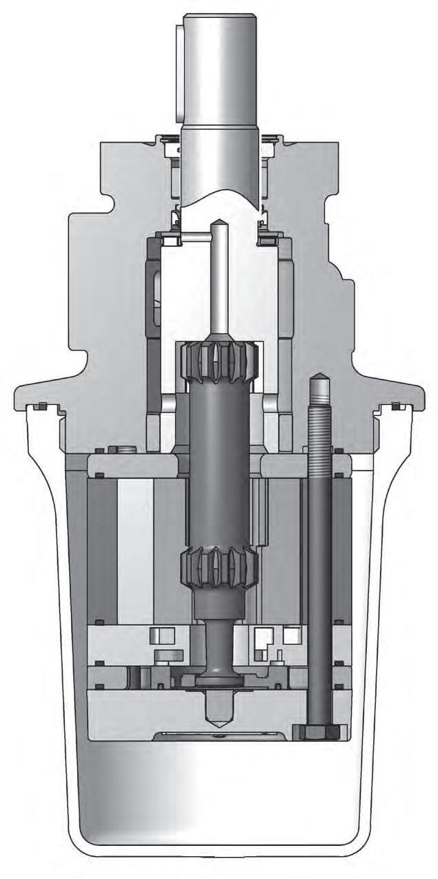
Torqmotor™ TS Series features include:
• The roller vane rotor set design offers a lowfriction, wear compensation which maximizes the useful performance life of the motor.
• Zero leak commutation valve provides greater, more consistent volumetric efficiency
• Design flexibility—TS offers the 316 stainless steel housing and shaft with a one-sizefits-all displacements polypropylene cover.
• Patented 60-40 spline member arrangement transmits more torque with less weight.
• Full flow lubrication maximizes cooling and may provide up to 50% longer life than motors not having this feature.
• Higher pressure rating provides greater torque than competitive brands.
• Full interchangeability with other motors which are designed according to industry standards.
• Compatible with most hydraulic systems with regard to pressure, torque and speed.
• A unique high-pressure shaft seal that eliminates the need for case drains.
• Up to 13 horsepower output.
Torqmotor™ TJ Series features include:
• The roller vane rotor set design offers a low-friction, wear compensation which maximizes the useful performance life of the motor.
• Zero leak commutation valve provides greater, more consistent volumetric efficiency.
• Patented 60-40 spline member arrangement transmits more torque with less weight.
• Full flow lubrication maximizes cooling and may provide up to 50% longer life than motors not having this feature.
• Higher pressure rating provides greater torque than competitive brands.
• Full interchangeability with other motors which are designed according to industry standards.
• Compatible with most hydraulic systems with regard to pressure, torque and speed.
• A unique high-pressure shaft seal that eliminates the need for case drains.
• Up to 23 horsepower output.
Parker Hannifin Corporation Hydraulic Pump/Motor Division Greeneville, TN 37745 US
5
HIGH PRESSURE SEAL HOUSING DRIVE LINK— 12-TOOTH SPLINES MATCHED ROTOR SET MATCHED COMMUTATOR SET 316 STAINLESS COUPLING SHAFT HIGH PRESSURE SEAL 316 STAINLESS HOUSING GLASS FILLED POLYPROPYLENE DIRT & WATER SEAL MATCHED ROTOR SET MATCHED COMMUTATOR SET DIRT & WATER SEAL COUPLING SHAFT
HY13-1526-001-M1/US Torqmotor™ Service Procedure
Introduction
This service manual has one purpose: to guide you in maintaining, troubleshooting, and servicing the TC, TS, TB, TE and TJ Torqmotor™ (low-speed, hightorque hydraulic motor).
Material in this manual is organized so you can work on the Torqmotor™ and get results without wasting time or being confused. To get these results, you should read this entire manual before you begin any work on the Torqmotor™.
This manual also contains troubleshooting information and checklist. If you must service the Torqmotor™, the checklist will help you to determine where the problem may be.
The three-column format of the Disassembly and Inspection, and Assembly sections will make it easier for you to conduct major work on the Torqmotor™. Column 1 gives a brief key for each procedure. Column 2 explains in detail the procedure you should follow. Column 3 illustrates this procedure with photographs. Read all material carefully and pay special attention to the notes, cautions, and warnings.
TC, TS, TB, TE and TJ Series
A page with the Torqmotor™ exploded assembly view is provided several places in this manual. The component part names and item numbers assigned on this exploded assembly view correspond with names and item numbers (in parentheses) used in the disassembly and assembly procedures set forth in this manual. Service part list charts are also provided in this manual with the part names and exploded view item numbers cross referenced to Parker service part numbers.
Service parts are available through the Original Equipment Manufacturer or Parker approved TC, TS, TB, TE and TJ Distributors.
As you gain experience in servicing the Torqmotor™, you may fnd that some information in this manual could be clearer or more complete. If so, let us know about it. Do not try to second guess the manual. If you are stuck, contact us. Servicing the Torqmotor™ should be a safe and productive procedure, in order for the unit to deliver the reliable, long-life operation engineered into it.
6
Parker Hannifin Corporation Hydraulic Pump/Motor Division Greeneville, TN 37745 US
HY13-1526-001-M1/US
Torqmotor™ Service Procedure
TC, TS, TB, TE and TJ Series
NOTE: Before troubleshooting any system problem, check service literature published by the equipment and/or component manufacturers. Follow their instructions, if given, for checking any component other than the Torqmotor™ unit.
Preparation
Make your troubleshooting easier by preparing as follows:
• work in a clean, well-lighted place;
• have proper tools and materials nearby;
• have an adequate supply of clean petroleum-basesolvent.
WARNING: SINCE SOLVENTS ARE FLAMMABLE, BE EXTREMELY CAREFUL WHEN USING ANY SOLVENT, EVEN A SMALL EXPLOSION OR FIRE COULD CAUSE INJURY OR DEATH.
WARNING: WEAR EYE PROTECTION AND BE SURE TO COMPLY WITH OSHA AND OTHER MAXIMUM AIR PRESSURE REQUIREMENTS.
Preliminary Checks
Hydraulic systems are often trouble-free. Hence, the problem an operator complains of could be cause by something other than the hydraulic components. Thus, once you have determined that a problem exists, start with the easy-to-check items, such as:
• parts damaged from impact that were not properly repaired, or that should have been replaced; and
• improper replacement parts used in previous servicing
• mechanical linkage problems such as binding, broken, or loose parts or slipping belts
Hydraulic Components
If you think the problem is caused by a hydraulic component, start by checking the easy-to-reach items. Check all hoses and lines for cracks, hardening, or other signs of wear. Reroute any usable hoses that are kinked, severely bent, or that rest against hot engine parts. Look for leaks, especially at couplings and fttings. Replace any hoses or lines that don’t meet system fow and pressure ratings.
Next, go to the reservoir and flter or flters. Check fuid level and look for air bubbles. Check the flter(s). A flter with a maximum 40 micron fltration is recommended for the Torqmotor™ system. Visually check other components to see if they are loosely mounted, show signs of leaks, or other damage or wear.
Excessive heat in a hydraulic system can create problems that can easily be overlooked. Every system has its limitation for the maximum amount of temperature. After the temperature is attained and passed, the following can occur:
• oil seal leaks
• loss of effciency such as speed and torque
• pump loss of effciency
• pump failure
• hoses become hard and brittle
• hose failure
A normal temperature range means an effcient hydraulic system. Consult the manuals published by equipment and/or component manufacturers for maximum allowable temperature and hydraulic tests that may be necessary to run on the performance of the hydraulic components. The Torqmotor™ is not recommended for hydraulic systems with maximum temperatures above 200°F (93.3°C).
7
Parker Hannifin Corporation Hydraulic Pump/Motor Division Greeneville, TN 37745 US
Guide
Troubleshooting
HY13-1526-001-M1/US
Troubleshooting Checklist
Torqmotor™ Service Procedure
TC, TS, TB, TE and TJ Series
Trouble Cause Remedy
Oil Leakage
1. Hose fttings loose, worn or damaged.
2. Oil seal rings (3) deteriorated by excess heat.
3. Special bolt (1, 1A, 1B or 1C) loose or its sealing area deteriorated by corrosion.
4. Internal shaft seal (14) worn or damaged.
5. Worn coupling shaft (10) and internal seal (14).
Check & replace damaged fttings or “O” Rings. Torque to manufacturers specifcations.
Replace oil seal rings by disassembling Torqmotor™ unit.
(a) Loosen then tighten single bolt to torque specifcation.
(b) Replace bolt.
Replace seal. Disassembly of Torqmotor™ unit necessary.
Replace coupling shaft and seal by disassembling Torqmotor™ unit.
Significant loss of speed under load
1. Lack of suffcient oil supply
(a) Check for faulty relief valve and adjust or replace as required.
(b) Check for and repair worn pump.
(c) Check for and use correct oil for temperature of operation.
Low mechanical efficiency or undue high pressure required to operate Torqmotor™ unit
2. High internal motor leakage
3. Severely worn or damaged internal splines.
4. Excessive heat.
1. Line blockage
2. Internal interference
3. Lack of pumping pressure
4. Excessive binding or loading in system external to Torqmotor™ unit.
Replace worn rotor set by disassembling Torqmotor™ unit.
Replace rotor set, drive link and coupling shaft by disassembling Torqmotor™ unit.
Locate excessive heat source (usually a restriction) in the system and correct the condition.
Locate blockage source and repair or replace.
Disassemble Torqmotor™ unit, identify and remedy cause and repair, replacing parts as necessary.
Check for and repair worn pump.
Locate source and eliminate cause.
CAUTION: If the hydraulic system fluid becomes overheated [in excess of 200°F (93.3°C)], seals in the system can shrink, harden or crack, thus losing their sealing ability.
Parker Hannifin Corporation Hydraulic Pump/Motor Division Greeneville, TN 37745 US
8
HY13-1526-001-M1/US Torqmotor™ Service Procedure
Tools and Materials Required for Servicing
• Clean, petroleum-based solvent
• Emery paper
• Vise with soft jaws
• Air pressure source
• Arbor press
• Screw driver
• Masking tape
• Breaker bar
• Torque wrench-ft. lbs. (N m)
• Sockets: 1/2 or 9/16 inch thin wall, 1 inch
• Allen Sockets: 3/16, 3/8 inch
• Adjustable crescent wrench or hose ftting wrenches
• SAE 10W40 SE or SF oil
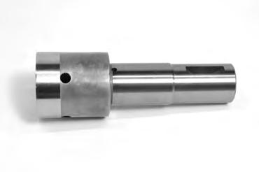
• Special bearing mandrel for TC, TS, TB & TE Torqmotors (SEE FIGURE 1)
• Feeler gage .005 inch (.13 mm)
• TC, TS, TB & TE Torqmotors require blind hole bearing puller for 1.06 inch (26.9) mm) and 1.62 inch (41.1 mm) diameter bearing/bushing.
• TJ requires blind hole bearing puller for 1.400 inch diameter (35.6 mm) and 2.130 inch diameter (5.41 mm) bearing
• Clean corrosion resistant grease. Part #406018 is included in each seal kit. Recommended grease is Parker Specifcation #045236 or Mobil Mobilith SHC® 460
NOTE: The available service seal kits include the recommended grease as a grease pack #406018
CAUTION: Mixing greases that have different bases can be detrimental to bearing life.
TC, TS, TB, TE and TJ Series Parker Hannifin
9
Corporation Hydraulic Pump/Motor Division Greeneville, TN 37745 US
HY13-1526-001-M1/US
Technical Information
Torqmotor™ Service Procedure
TC, TS, TB, TE and TJ Series
CONVERSIONS
Torque Chart
- TC has two steel bushing internal of housing press frst steel bushing 1.223 deep from housing face the second steel bushing press .03 below face
(Fabricate if considered necessary)
(Fabricate if considered necessary)
Parker
Hydraulic Pump/Motor
10
Hannifin Corporation
Division Greeneville, TN 37745 US
INCHES mm INCHES mm .020 .51 1.060 26.92 .021 .53 1.295 32.89 .029 .74 1.297 32.94 .030 .76 1.396 35.46 .111 2.81 1.398 35.51 .119 3.02 1.620 41.15 .152 3.86 1.622 41.20 .160 4.06 1.983 50.37 .296 7.52 1.985 50.42 .304 7.72 2.120 53.85 .460 11.68 2.122 53.90 .470 11.94 2.233 56.72 .500 12.70 2.235 56.77 .585 14.86 2.483 63.07 .595 15.11 2.485 63.12 .660 16.76 2.500 63.5 .675 17.15 2.88 73.2 1.058 26.87
Part Name Item Number Torque bolt 5/16 24 UNF 2A 1, 1A, 1B or 1C 25-30 ft. lbs. (33-40 N m) bolt 5/8 18 UNF 2A 10D 140-180 ft. lbs. (190-244 N m) nut 3/4 16 UNF 2B 27A (TC, TB, TE) 175-255 ft. lbs. (237-305 N m) Castle nut 1-20 UNEF 2B 27A (TJ) 300-400 ft. lbs. (407-542 N m)
Figure 1 – TC, TS, TB & TE
Figure 2 – TJ
HY13-1526-001-M1/US
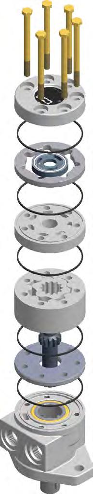
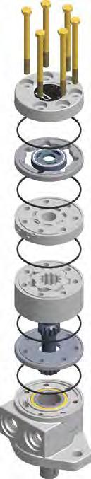
Torqmotor™ Exploded View
Typical Assembly
Torqmotor™ Service Procedure
TC, TS, TB, TE and TJ Series
Parker
11
Hannifin Corporation Hydraulic Pump/Motor Division Greeneville, TN 37745 US
Item No. Description 1. Special Bolt (6) 2. End Cover 3. Seal Ring (5) 4. Seal Ring-Commutator 5. Commutator Assembly (Matched Set) 6. Manifold 7. Rotor Set (Matched Set) 8. Wear Plate 9. Drive Link 10. Coupling Shaft 11. Steel Bushing 12. Thrust Bearing 13. Thrust Washer (TJ Series Qty=2) 14. Shaft Seal Item No. Description 15. Back Up Washer 16. Back Up Ring 17. Housing 18. Steel Bushing 19. Dirt & Water Seal 20. O-Ring (2) 21. Plug (2) 22. Relief Valve (2) 23. Plug (2) 24. Shuttle Valve 25. Spring (2) 26. Key 27a. Castle Nut 27b. Patch Nut MATCHED SET REAR PO RT OPTION COMPONENTS ASSEMBLE WITH WEDGE SIDE OF COMMUTATOR SEAL DOWN INTO COMMUTATOR FACE TORQUE TO 25-30 FT LBS [34-41 Nm] (6 BOLTS) 1 10 9 11 3 4 5 3 6 3 7 3 8 3 2 19 18 17 16 15 14 13 12 20 24 23 25 21 22 21 22 RELIEF VALVE END COVER SHUTTLE VALVE END COVER 23 26 27b 27a 13 THIS COMPONENT INCLUDED IN TJ TORQMOTORS ON LY
HY13-1526-001-M1/US
Torqmotor™ Service Procedure
TC, TS, TB, TE and TJ Series
12
Parker Hannifin Corporation Hydraulic Pump/Motor Division Greeneville, TN 37745 US
HY13-1526-001-M1/US
Torqmotor™ Seal Letter
Torqmotor™ Service Procedure
TC, TS, TB, TE and TJ Series
In July 2012, a change was made to our small frame (Series TC, TS, TB, TE and TJ) low speed high torque Torqmotors™.
The motors are comprised of six sections. There is a seal between each section to resist external leakage. The design of the motor dictates that it be assembled from front (shaft end) to rear. This means that the motor must be assembled shaft down. Some of the O-ring grooves in the current design are facing down during assembly. To keep the O-rings in place during assembly, they are coated with grease.
After assembly, this grease can seep out. This is often misdiagnosed as external hydraulic fuid leakage, causing the customer to think that the motor is faulty. It also can cause problems when the motor is painted.
To correct this problem, we have re-positioned the section O-ring grooves on fve of the six parts (all but the front housing) so that the O-ring grooves are all facing up during assembly. It will now be possible to install the O-rings dry, eliminating the problem.
The part numbers of the fve re-designed parts will change, but the complete model number (TE0080AS100AAAA etc) will not change. The change occurred on July 1, 2012. The new design is identifed by the Julian date code on the motor. All TC, TS, TB, TE and TJ motors dated after Julian date 183-12 (183rd day of 2012) will be of the newer design. Seals and seal kits will be unaffected. Typical model number changes and seal groove locations are illustrated on page 15.
Made before July 1, 2012
Made on or after July 1, 2012
MADE IN USA
MADE IN USA
Notice: For individual part numbers for these series TC, TS, TB, TE and TJ prior to manufactory date code of 182-2012 please refer to the parts list on pages 18-26.
Parker Hannifin Corporation Hydraulic Pump/Motor Division Greeneville, TN 37745 US
13
18312- ####
18212- ####
Seal groove
No seal groove
Seal groove (both faces) Seal groove (bottom face only)
No seal groove
 HY13-1526-001-M1/US Torqmotor™ Service Procedure TC, TS, TB, TE and TJ Series
14 1 2 4 5 6 7 8 17
Parker Hannifin Corporation Hydraulic Pump/Motor Division Greeneville, TN 37745 US
TC, TB, TE and TJ Assembly before July 1, 2012
IN USA
MADE
18212- ####
Torqmotor™ Exploded View
HY13-1526-001-M1/US Torqmotor™ Service Procedure TC, TS, TB, TE and TJ Series Parker
TN 37745
15 1 2 4 5 6 7 8 17 TC, TB, TE and TJ Assembly on or after July 1, 2012 Torqmotor™ Exploded View MADE IN USA 18312- #### ItemQTYNew Part #Old Part #Description 81477376 477341 Wear Plate 7 1TE127003 MF127003 Rotor Set 61TE015000 MF015000 Manifold 4 & 51TE018000A1MF018000A1Commutator Assembly 21TE016000 MF016007 End Cover No seal groove Seal groovetop face only
Hannifin Corporation Hydraulic Pump/Motor Division Greeneville,
US
Torqmotor™ Exploded View
TS Series Assembly before July 1, 2012
Parker
Corporation
Pump/Motor Division
TN 37745 US 16 17 25 16 20 4 4 4 3 24 13 18 14 15 19 12A 12 7 2 1 5&6 10 23 9 8A 22 Assemble wi th wedg eside downint ocommutatorf ace. Torq ue Bolt
34-41 Nm ( 25- 30 ft -lbs) 25 17 16
HY13-1526-001-M1/US Torqmotor™ Service Procedure TC, TS, TB, TE and TJ Series
Hannifin
Hydraulic
Greeneville,
sTo
MADE IN USA 18212- ####
No. Description
Item
1. Special Bolt (6)
2. End Cover
3. Seal Ring-Commutator
4. Seal Ring (5)
5 & 6. Commutator Assembly (Matched Set)
Item No. Description 9. Wear
10. Drive
12.
12A. Stainless
13.
14. Thrust
15. Thrust
16.
Item No. Description 17. Back Up Ring 18. Housing 19. Steel Bushing 20. Dirt & Water Seal 22. Cover O-Ring 23. Protective Cover 24. Snap Ring 25. Back Up Washer
7. Manifold 8A. Rotor Set (Matched Set)
Plate
Link
Coupling Shaft
Key
Steel Bushing
Washer
Bearing
Shaft Seal
Parker
Corporation
Division
37745 US 17 24 20 13 18 8A 7 5&6 Assemblewithwedgeside downintocommutatorface. 23 22 1 2 TorqueBoltsTo 34-41Nm (25-30ft-lbs) 3 4 4 9 10 16 25 17 12 12A 19 15 14 17 25 16 4 4
on
1, 2012
Exploded View MADE IN USA 18312- ####
No. Description
HY13-1526-001-M1/US Torqmotor™ Service Procedure TC, TS, TB, TE and TJ Series
Hannifin
Hydraulic Pump/Motor
Greeneville, TN
TS Series Assembly
or after July
Torqmotor™
Item
1. Special Bolt (6)
2. End Cover
3. Seal Ring-Commutator
4. Seal Ring (5)
5 & 6. Commutator Assembly (Matched Set)
Item No. Description 9. Wear
10. Drive
12.
12A. Stainless
13.
14. Thrust
15. Thrust
16.
Item No. Description 17. Back Up Ring 18. Housing 19. Steel Bushing 20. Dirt & Water Seal 22. Cover O-Ring 23. Protective Cover 24. Snap Ring 25. Back Up Washer
7. Manifold 8A. Rotor Set (Matched Set)
Plate
Link
Coupling Shaft
Key
Steel Bushing
Washer
Bearing
Shaft Seal
HY13-1526-001-M1/US
TC Service Parts List Chart
Chart Use Example:
Torqmotor™ Service Procedure
TC, TS, TB, TE and TJ Series
TC0045AS010AAAB Torqmotor™ includes part numbers listed to the right of TC (SERIES), 0045 (DISP.), AS (MOUNTING/ PORTING), 01(SHAFT), 0 (ROTATION), and AAAB (OPTION) shown in the left hand column of the chart.
Caution:
The charted component service information is for the Torqmotors listed only. Refer to the original equipment manufacturer of the equipment using the Torqmotor for assembly numbers not listed below.
Parker Hannifin Corporation Hydraulic Pump/Motor Division
37745 US 18 EXPLODED VIEW ITEM # 5 6 8 11 13 12 16 18 19 15 COMMUTATOR MANIFOLD WEAR STEEL THRUST THRUST BACKUP STEEL DIRT & WATER BACKUP DESCRIPTION & RING ASSY (SEE NOTE) PLATE BUSHING WASHER BEARING RING BUSHING SEAL WASHER TC- Service Part # TE018000A1 TE015000 477376 069511* 028483 065066 028516 478036 028552 (*quantity 2) SERIES
Greeneville, TN
EXPLODED VIEW ITEM # 2 1,217 A20 DESCRIPTION HOUSING MOUNTING PORTING END COVER SERVICE PART # O-RING (2) AT- SAE A (2 Bolt) 1/2” BSPF TB016000 ML012012A1 AS- SAE A (2 Bolt) 7/8” O-Ring TB016000 ML012001A1 FS- 4 Bolt 7/8” O-Ring TB016000 ML012005A1 AM- SAE A (2 Bolt) Manifold TB016000 ML012008A1 032790 FM- 4 Bolt Manifold TB016000 ML012006A1 032790 AP- SAE A (2 Bolt) 1/2” NPTF TB016000 ML012002A1 FP- 4 Bolt 1/2” NPTF TB016000 ML012007A1 FF- 4 Bolt 3/4” O-Ring TB016000 ML012013A1 HOUSING GROUP Mounting Code Porting Code FRONT PORTING EXPLODED VIEW (Select Item # Bolt Per Option Group) ITEM # 1 OR 1A OR 1C ROTOR THICKNESS7A 7B 9“L” Dim DISPLACEMENT (in3/rev) BOLT # (BOLT LENGTH - 5 bolts required) “L” DIM OF ROTOR THICKNESS ROTOR SET FREE RUNNING ROTOR SET†† DRIVE LINK Overall Length 0036-2.2 021356 (2.625) .2750 TE017003TE017005MF013000 2.975 0045-2.7 021311 (2.750) 021443 (3.440) 021308 (3.875) .3169 TE027003TE027005MF023000 3.021 0050-3.0 021311 (2.750) 021444 (3.500) 021308 (3.875) .3751 TE037003TE037005MF033000 3.080 0065-4.0 021306 (2.875) 021358 (3.625) 021435 (4.000) .5001 TE047003TE047005MF043000 3.206 0080-5.0 021382 (3.000) 021438 (3.750) 021359 (4.125) .6258 TE057003TE057005MF053000 3.334 0100-6.0 021357 (3.125) 021308 (3.875) 021445 (4.250) .7508 TE067003TE067005MF063000 3.460 0130-8.0 021307 (3.375) 021359 (4.125) 021439 (4.500) 1.0008 TE087003TE087005MF083000 3.712 0165-9.9 021358 (3.625) 021310 (4.375) 021384 (4.875) 1.2508 TE107003TE107005MF103000 3.969 0195-11.9 021308 (3.875) 021383 (4.625) 021465 (5.000) 1.5008 TE127003TE127005MF123000 4.215 0230-13.9 021359 (4.125) 021384 (4.875) 021460 (5.250) 1.7508 TE147003TE147005MF143000 4.467 0260-15.9 021310 (4.375) 021446 (5.125) 021467 (5.750) 2.0008 TE167003TE167005MF163000 4.718 0295-17.9 021383 (4.625) 021414 (5.375) 021467 (5.750) 2.2508 TE187003TE187005MF183000 4.970 0330-20.0 021384 (4.875) 021459 (5.625) 021448 (6.000) 2.5008 TE207003TE207005MF203000 5.220 0365-22.6 021460 (5.250) 021448 (6.000) 021469 (6.375) 2.8406 TE227003N/AMF223000 5.557 0390-24.0 021414 (5.375) 021449 (6.125) 021464 (6.531) 3.0030 TE247003N/AMF243000 5.716 †† Free running rotorset is not available in 0365 or 0390 displacements.
Not released.
has two steel bushing press internal of housing. DISPLACEMENT GROUP
*
TC
HY13-1526-001-M1/US
TC Service Parts List Chart
Torqmotor™ Service Procedure
TC, TS, TB, TE and TJ Series
1 Service housing assembly ITEM #17 with part number suffix-J2 includes ITEMS #11, #16, #15, #14, #13, #12 and #19.
2 Order (2) #032790 ITEM #17A for service housing assembly where manifold ports are used.
Standard seal kit #SK000090 includes six #032821 seal rings, #032435 commutator seal, #032377 inner seal, #028516 back up washer, #478036 dirt & water seal, #406018 grease pack, bulletin #050015 and 028552 steel backup washer.
Special seal kit #SK000091 for units that use fire retardant fluids include six #032822 seal rings, #032435 commutator seal, #032809 inner seal, #028516 back up washer, #478036 dirt & water seal, #406018 grease pack, bulletin #050015 and 028552 steel backup washer.
High Temp commutator seal 032861.
For reverse timed manifold, use TE015001.
* Speed sensor not available in TC Series.
High Temp commutator seal kit #SK000100 includes six #032821 seal rings, #032861 commutator seal, #032377 inner seal, #028516 back up washer, #478036 dirt & water seal, #406018 grease pack, #bulletin 050015 and #028552 steel backup washer.
High Temp commutator/Fluorocarbon shaft seal kit #SK000230 includes six #032821 seal rings, #032861 High Temp commutator seal, #032809 Fluorocarbon shaft seal, #028516 back-up washer, #478036 dirt and water seal, #406018 grease pack, bulletin 050015 and #028552 steel back-up washer.
Hannifin Corporation Hydraulic Pump/Motor Division Greeneville, TN 37745 US
Parker
19
EXPLODED VIEW ITEM # 2 4 3 14 23 20 25 24 & 25 END COMMUTATOR SEAL INNER PLUG & O-RING SPRING VALVE DESCRIPTION BOLTS (5) COVER SEAL RING (5) SEAL O-RING ASSY W/SPRING AAAB No Paint Item #1 032435 032821 032377 AAAC Corrosion Resistant Paint Item #1 032435 032821 032377 AAAH Fluorocarbon Seals Item #1 032435 032822 032809 BBCK 1740 PSI Internal Bidirectional Item #1C TE016006A7 032435 032821 032377 411068A1 032750 401660 4100107 Relief, No Paint BBCM 1200 PSI Internal Bidirectional Item #1C TE016006A31 032435 032821 032377 411068A1 032750 401660 41001031 Relief, No Paint BBCN 2030 PSI Internal Bidirectional Item #1C TE016006A5 032435 032821 032377 411068A1 032750 401660 4100105 Relief, No Paint BBCP 1450 PSI Internal Bidirectional Item #1C TE016006A10 032435 032821 032377 411068A1 032750 401660 41001010 Relief, No Paint BBCT 1560 PSI Internal Bidirectional Item #1C TE016006A2 032435 032821 032377 411068A1 032750 401660 4100102 Relief, No Paint BBCP 1450 PSI Internal Bidirectional Item #1C TE016006A10 032435 032821 032377 411068A1 032750 401660 41001010 Relief, No Paint AAJV Bidirectional Shuttle Valve Item #1A TE016003A1 032435 032821 032377 036297 032750 401660 415603 (3:30), Black Paint AABW Fluorocarbon Seal, Double Paint Item #1 TB016000 032435 032821 032377 AAAG Fluorocarbon Seals, Black Paint Item #1 TB016000 032435 032821 032377 AABJ Free Running Rotor Set, Black Paint Item #1 TB016000 032435 032821 032377 AABK Free Running Rotor Set, No Paint Item #1 TB016000 032435 032821 032377 OPTION GROUP EXPLODED VIEW ITEM # 10 COUPLING WOODRUFF DESCRIPTION SHAFT KEY NUT 01- Long 6B Snapwire Groove ML019010 09- 1” Ø, 0.38 Pinhole, 0.55” from end ML019005 10- 1” Short Woodruff Key 1/4” Tap ML019002 038015 (1/4x1) 11- 1” Short 6B Spline, 1/4” Snapwire Groove ML019001 13- 1” Long Woodruff Snapwire Groove ML019006 038015 (1/4x1) 15- 1” Ø, 0.32 Pinhole 0.4” from end ML019011 21- “-10 Code” plus Corrosion Resistant Nitrotec ML019008 26- 25 mm Straight with 8 mm Keyway ML019003 039047 (8mmx7mm) 28- 13 Tooth Spline 16/32 Pitch ML019007 72- Short Woodruff Key 1/4” Tap ML019009 038015 (1/4x1) COUPLING SHAFT GROUP
HY13-1526-001-M1/US
TS Service Parts List Chart
Chart Use Example:
Torqmotor™ Service Procedure
TC, TS, TB, TE and TJ Series
TS0045FS770AAXH Torqmotor™ includes part numbers listed to the right of TS (SERIES), 0045 (DISP.), FS (MOUNTING/ PORTING), 77(SHAFT), 0 (ROTATION), and AAXH (OPTION) shown in the left hand column of the chart.
Caution:
The charted component service information is for the Torqmotors listed only. Refer to the original equipment manufacturer of the equipment using the Torqmotor for assembly numbers not listed below.
Parker
20 EXPLODED VIEW ITEM # 5 7 9 13 14 15 17 19 20 25 COMMUTATOR MANIFOLD WEAR STEEL THRUST THRUST BACKUP STEEL DIRT & WATER BACKUP DESCRIPTION & RING ASSY (SEE NOTE) PLATE BUSHING WASHER BEARING RING BUSHING SEAL WASHER TS- Service Part # TE018000A1 TE015000 477376 069511 028483 065066 028516 065071 478010 028552 SERIES
Hannifin Corporation Hydraulic Pump/Motor Division Greeneville, TN 37745 US
EXPLODED VIEW ITEM # 2 18 4 16 DESCRIPTION 6 BOLT HOUSING SHAFT MOUNTING PORTING END COVER SERVICE PART O-RING (5) SEAL FS- 4 Bolt 7/8” O-Ring TB016000 TS012201A2 032822 032809 HOUSING GROUP Mounting Code Porting Code FRONT PORTING ONLY EXPLODED VIEW ROTOR ITEM # 1 THICKNESS 8A 8B 10 “L” Dim DISPLACEMENT “L” DIM OF ROTOR FREE RUNNING DRIVE Overall (in3/rev) BOLT # (BOLT LENGTH - 6 bolts required) ROTOR THICKNESS SET ROTOR SET†† LINK Length 0036- 2.2 021356 (2.625) .2750 TE017003 TE017005 MF013000 2.975 0045- 2.7 021311 (2.750) .3169 TE027003 TE027005 MF023000 3.021 0050- 3.0 021311 (2.750) .3751 TE037003 TE037005 MF033000 3.080 0065- 4.0 021306 (2.875) .5001 TE047003 TE047005 MF043000 3.206 0080- 5.0 021382 (3.000) .6258 TE057003 TE057005 MF053000 3.334 0100- 6.0 021357 (3.125) .7508 TE067003 TE067005 MF063000 3.460 0130- 8.0 021307 (3.375) 1.0008 TE087003 TE087005 MF083000 3.712 0165- 9.9 021358 (3.625) 1.2508 TE107003 TE107005 MF103000 3.969 0195- 11.9 021308 (3.875) 1.5008 TE127003 TE127005 MF123000 4.215 0230- 13.9 021359 (4.125) 1.7508 TE147003 TE147005 MF143000 4.467 0260- 15.9 021310 (4.375) 2.0008 TE167003 TE167005 MF163000 4.718 0295- 17.9 021383 (4.625) 2.2508 TE187003 TE187005 MF183000 4.970 0330- 20.0 021384 (4.875) 2.5008 TE207003 TE207005 MF203000 5.220 0365- 22.6 021460 (5.250) 2.8406 TE227003 N/A MF223000 5.557 0390- 24.0 021414 (5.375) 3.0030 TE247003 N/A MF243000 5.716 †† Free running rotorset is not available in 0365 or 0390 displacements. * Not released. DISPLACEMENT GROUP EXPLODED VIEW ITEM # 12 12A 23 24 22 COUPLING STAINLESS PROTECTIVE RETAINING COVER DESCRIPTION SHAFT KEY COVER RING O-RING 77- 1” Dia. 1/4” Square Key, 1/4”-20 Tap TS019400 039053 (1/4x1/4x1.33) 420007 401083 032013 STAINLESS STEEL COUPLING SHAFT GROUP OPTION GROUP EXPLODED VIEW ITEM # 3 22 23 COMMUTATOR COVER PROTECTIVE DESCRIPTION SEAL O-RING COVER AAXH Fluorocarbon (Viton) Dirt & Water Seal, Protective Motor Cover w/Fluorocarbon (Viton) Seal, 032861 032013 420007 Stainless Steel Housing & Shaft, Fluorocarbon (Viton) (Body & Shaft Seals), High Temp Commutator Seal, No Paint AAXW Fluorocarbon (Viton) Dirt & Water Seal, Protective Motor Cover w/Fluorocarbon (Viton) Seal, 032861 032013 420007 Stainless Steel Housing & Shaft, Fluorocarbon (Viton) (Body & Shaft Seals), High Temp Commutator Seal, High Temp Thrust Bearing, No Paint
HY13-1526-001-M1/US
TB Service Parts List Chart
Chart Use Example:
Torqmotor™ Service Procedure
TC, TS, TB, TE and TJ Series
TB0045AS010AAAB Torqmotor™ includes part numbers listed to the right of TB (SERIES), 0045 (DISP.), AS (MOUNTING/ PORTING), 01(SHAFT), 0 (ROTATION), and AAAB (OPTION) shown in the left hand column of the chart.
Caution:
The charted component service information is for the Torqmotors listed only. Refer to the original equipment manufacturer of the equipment using the Torqmotor for assembly numbers not listed below.
are the same as rear ported units if you are using the same displacement.
or 0390 displacements.
21 EXPLODED VIEW ITEM # 5 6 8 11 13 12 16 18 19 15 COMMUTATOR MANIFOLD WEAR BRONZE THRUST THRUST BACKUP “DU” DIRT & WATER BACKUP DESCRIPTION & RING ASSY (SEE NOTE) PLATE BUSHING WASHER BEARING RING BEARING SEAL WASHER TB- Service Part # TE018000A1 TE015000 477376 069511 028483 065066 028516 065505 478036 028552 SERIES
Parker Hannifin Corporation Hydraulic Pump/Motor Division Greeneville, TN 37745 US
EXPLODED VIEW ITEM # 2 1,217 A20 DESCRIPTION HOUSING MOUNTING PORTING END COVER SERVICE PART # O-RING (2) MS- Standard (4 Bolt) 7/8” O-Ring TB016000 MF012014A2 AS- SAE A (2 Bolt) 7/8” O-Ring TB016000 MF012001A2 FS- 4 Bolt 7/8” O-Ring TB016000 MF012003A2 AM- SAE A (2 Bolt) Manifold TB016000 MF012004A2 032790 FM- 4 Bolt Manifold TB016000 MF012005A2 032790 MM- Standard (4 Bolt) Manifold TB016000 MF012049A2 032790 AP- SAE A (2 Bolt) 1/2” NPTF TB016000 MF012006A2 FP- 4 Bolt 1/2” NPTF TB016000 MF012007A2 AT- SAE A (2 Bolt) 1/2” BSPF TB016000 MF012011A2 BP- SAE B (2 Bolt) 1/2” NPTF TB016000 MF012073A2 HOUSING GROUP Mounting Code Porting Code EXPLODED VIEW ITEM # 2 1,B17 20 DESCRIPTION HOUSING MOUNTING PORTING END COVER SERVICE PART # O-RING (2) AR- SAE A (2 Bolt) Rear (3/4”-16 SAE O-Ring) TE016001 MF012008A2 FR- 4 Bolt Rear (3/4”-16 SAE O-Ring) TE016001 MF012010A2 BR- SAE B (2 Bolt) Rear (3/4”-16 SAE O-Ring) TE016001 MF012076A2 REAR PORTING Mounting Code Porting Code FRONT PORTING DISPLACEMENT GROUP EXPLODED VIEW (Select Item # Bolt Per Option Group) ROTOR ITEM # 1 OR 1A OR 1C THICKNESS7A 7B 9“L” Dim DISPLACEMENT (in3/rev) BOLT # (BOLT LENGTH - 5 bolts required)† “L” DIM OF ROTOR THICKNESS ROTOR SET FREE RUNNING ROTOR SET†† DRIVE LINK Overall Length 0036-2.2 021356 (2.625) .2750 TE017003TE017005MF013000 2.975 0045-2.7 021311 (2.750) 021443 (3.440) 021308 (3.875) .3169 TE027003TE027005MF023000 3.021 0050-3.0 021311 (2.750) 021444 (3.500) 021308 (3.875) .3751 TE037003TE037005MF033000 3.080 0065-4.0 021306 (2.875) 021358 (3.625) 021435 (4.000) .5001 TE047003TE047005MF043000 3.206 0080-5.0 021382 (3.000) 021438 (3.750) 021359 (4.125) .6258 TE057003TE057005MF053000 3.334 0100-6.0 021357 (3.125) 021308 (3.875) 021445 (4.250) .7508 TE067003TE067005MF063000 3.460 0130-8.0 021307 (3.375) 021359 (4.125) 021439 (4.500) 1.0008 TE087003TE087005MF083000 3.712 0165-9.9 021358 (3.625) 021310 (4.375) 021384 (4.875) 1.2508 TE107003TE107005MF103000 3.969 0195-11.9 021308 (3.875) 021383 (4.625) 021465 (5.000) 1.5008 TE127003TE127005MF123000 4.215 0230-13.9 021359 (4.125) 021384 (4.875) 021460 (5.250) 1.7508 TE147003TE147005MF143000 4.467 0260-15.9 021310 (4.375) 021446 (5.125) 021467 (5.750) 2.0008 TE167003TE167005MF163000 4.718 0295-17.9 021383 (4.625) 021414 (5.375) 021467 (5.750) 2.2508 TE187003TE187005MF183000 4.970 0330-20.0 021384 (4.875) 021459 (5.625) 021448 (6.000) 2.5008 TE207003TE207005MF203000 5.220 0365-22.6 021460 (5.250) 021448 (6.000) 021469 (6.375) 2.8406 TE227003N/AMF223000 5.557 0390-24.0 021414 (5.375) 021449 (6.125) 021464 (6.531) 3.0030 TE247003N/AMF243000 5.716 † Bolts for TB Series front ported units
†† Free running rotorset is not
0365
* Not released.
available in
HY13-1526-001-M1/US
TB Service Parts List Chart
Torqmotor™ Service Procedure
TC, TS, TB, TE and TJ Series
Note: Rear ported TB motors have 5 bolts at the back end cover.
1 Service housing assembly ITEM #17 with part number suffix-A2 includes ITEM #11 and #18.
2 Order (2) #032790 ITEM #17A for service housing assembly where manifold ports are used.
Standard seal kit #SK000090 includes six #032821 seal rings, #032435 commutator seal, #032377 inner seal, #028516 back up washer, #478036 dirt & water seal, #406018 grease pack, bulletin #050015 and 028552 backup washer.
Special seal kit #SK000091 for units that use fire retardant fluids include six #032822 seal rings, #032435 commutator seal, #032809 inner seal, #028516 back up washer, #478036 dirt & water seal, #406018 grease pack, bulletin #050015 and 028552 backup washer.
High Temp commutator seal 032861.
For reverse timed manifold, use TE015001.
* Speed sensor not available in TB Series.
Commutator set for rear ported units TE018001A1
High Temp commutator seal kit #SK000100 includes six #032821 seal rings, #032861 commutator seal, #032377 inner seal, #028516 back up washer, #478036 dirt & water seal, #406018 grease pack, #bulletin 050015 and #028552 steel backup washer.
High Temp commutator/Viton shaft seal kit #SK000230 includes six #032821 seal rings, #032861 High Temp commutator seal, #032809 Viton shaft seal, #028516 backup washer, #478036 dirt and water seal, #406018 grease pack, bulletin 050015 and #028552 steel back-up washer.
Parker Hannifin Corporation Hydraulic Pump/Motor Division Greeneville, TN 37745 US
22
EXPLODED VIEW ITEM # 2 4 3 14 23 20 25 24 & 25 END COMMUTATOR SEAL INNER PLUG & O-RING SPRING VALVE DESCRIPTION BOLTS (5) COVER SEAL RING (5) SEAL O-RING ASSY W/SPRING AAAB No Paint Item #1 032435 032821 032377 AAAC Corrosion Resistant Paint Item #1 032435 032821 032377 AAAH Fluorocarbon Seals Item #1 032435 032822 032809 BBCK 1740 PSI Internal Bidirectional Item #1C TE016006A7 032435 032821 032377 411068A1 032750 401660 4100107 Relief, No Paint BBCM 1200 PSI Internal Bidirectional Item #1C TE016006A31 032435 032821 032377 411068A1 032750 401660 41001031 Relief, No Paint BBCN 2030 PSI Internal Bidirectional Item #1C TE016006A5 032435 032821 032377 411068A1 032750 401660 4100105 Relief, No Paint BBCP 1450 PSI Internal Bidirectional Item #1C TE016006A10 032435 032821 032377 411068A1 032750 401660 41001010 Relief, No Paint BBCT 1560 PSI Internal Bidirectional Item #1C TE016006A2 032435 032821 032377 411068A1 032750 401660 4100102 Relief, No Paint BBCP 1450 PSI Internal Bidirectional Item #1C TE016006A10 032435 032821 032377 411068A1 032750 401660 41001010 Relief, No Paint AAJV Bidirectional Shuttle Valve Item #1A TE016003A1 032435 032821 032377 036297 032750 401660 415603 (3:30), Black Paint OPTION GROUP EXPLODED VIEW ITEM # 10 COUPLING WOODRUFF DESCRIPTION SHAFT KEY NUT 01- Long 6B Snapwire Groove MF019007 09- 1” Ø, 0.38 Pinhole, 0.55” from end MF019000 10- 1” Short Woodruff Key 1/4” Tap MF019006 038015 (1/4x1) 11- 1” Short 6B Spline, 1/4” Snapwire Groove MF019003 12- 1” Tapered (Short) MF019004 038015 (1/4x1) 025136 13- 1” Long Woodruff Snapwire Groove MF019005 038015 (1/4x1) 14- 1” Ø, Double Pinhole MF019001 15- 1” Ø, 0.32 Pinhole 0.4” from end MF019002 21- “-10 Code” plus Corrosion Resistant MF019008 22- 25 mm Straight with 7 mm Keyway, 6 mm Tap MF019009 039041 23- Short 6B Spline 5/16” Tap MF019010 25- 1” Tapered SAE MF019011 038015 (1/4x1) 025136 26- 25 mm Straight with 8 mm Keyway MF019012 039047 (8mmx7mm) 28- 13 Tooth Spline MF019014 29- 1” Taper 3/4-16 Thread MF019015 33- 1” Tapered, 3/16 Key, 3/4-16 Thd MF019016 038014 (3/16x3/4) 025156 Slotted Nut 40- Short Wood, 6mm Tap MF019021 50- 1” w.406 dia pinhole .62 from end 1/4-20 Tap MF019032 66- 26 code plus Nitrotec C MF019044 69- 25mm Straight w/8mm key 8mm Tap Stainless Steel MF019412 70- 1” Dia. Short Woodkey 1/4” Tap Stainless Steel MF019406 COUPLING
SHAFT GROUP
HY13-1526-001-M1/US
TE Service Parts List Chart
Chart Use Example:
Torqmotor™ Service Procedure
TC, TS, TB, TE and TJ Series
TE0045AS010AAAB Torqmotor™ includes part numbers listed to the right of TE (SERIES), 0045 (DISP.), AS (MOUNTING/ PORTING), 01(SHAFT), 0 (ROTATION), and AAAB (OPTION) shown in the left hand column of the chart.
Caution:
The charted component service information is for the Torqmotors listed only. Refer to the original equipment manufacturer of the equipment using the Torqmotor for assembly numbers not listed below.
23 EXPLODED VIEW ITEM # 5 6 8 11 13 12 16 18 19 15 COMMUTATOR MANIFOLD WEAR REAR RADIAL THRUST THRUST BACKUP FRONT RADIAL DIRT & WATER BACKUP DESCRIPTION & RING ASSY (SEE NOTE) PLATE BEARING WASHER BEARING RING BEARING SEAL WASHER TE- Service Part # TE018000A1 TE015000 477376 069512 028483 065066 028516 065506 478036 028552
Parker Hannifin Corporation Hydraulic Pump/Motor Division Greeneville, TN 37745 US
SERIES
EXPLODED VIEW SPEED SENSOR ITEM # 2 1,417 17 1,220 DESCRIPTION 6 BOLT 5 BOLT HSG 6 BOLT HSG 6 BOLT HSG MOUNTING PORTING END COVER SERVICE PART # SERVICE PART # O-RING (2) SERVICE PART # SENSOR MS- Standard (4 Bolt) 7/8” O-Ring TE016000 MF012014A1 MF012214A1 MF012314A1 455063 AS- SAE A (2 Bolt) 7/8” O-Ring TE016000 MF012001A1 MF012201A1 MF012301A1 455063 US- Wheel Mount 7/8” O-Ring TE016000 MF012002A1 MF012202A1 MF012302A1 455063 FS- 4 Bolt 7/8” O-Ring TE016000 MF012003A1 MF012203A1 MF012303A1 455063 AM- SAE A (2 Bolt) Manifold TE016000 MF012004A1 MF012204A1 032790 MF012304A1 455063 FM- 4 Bolt Manifold TE016000 MF012005A1 MF012205A1 032790 MM- Standard (4 Bolt) Manifold TE016000 MF012049A1 MF012249A1 032790 AP- SAE A (2 Bolt) 1/2” NPTF TE016000 MF012006A1 MF012206A1 MF012306A1 455063 FP- 4 Bolt 1/2” NPTF TE016000 MF012007A1 MF012207A1 MF012307A1 455063 AT- SAE A (2 Bolt) 1/2” BSPF TE016000 MF012011A1 MF012211A1 EXPLODED VIEW SPEED SENSOR ITEM # 2 1,417 DESCRIPTION 5 BOLT 5 BOLT HSG 5 BOLT HSG MOUNTING PORTING END COVER SERVICE PART # SERVICE PART # SENSOR MR- Standard (4 Bolt) Rear Port (3/4”-16 SAE O-Ring) TE016001 MF012021A1 UR- Small Wheel Mount Rear Port (3/4”-16 SAE O-Ring) TE016001 MF012009A1 N/A 455063 FR- 4 Bolt Mount Rear Port (3/4”-16 SAE O-Ring) TE016001 MF012010A1 AR- SAE A (2 Bolt) Rear Port (3/4”-16 SAE O-Ring) TE016001 MF012008A1 N/A 455063 NOTE: Rear ported TE motors always have 5 bolts at the back end cover. HOUSING GROUP Mounting Code Porting Code REAR PORTING FRONT PORTING Mounting Code Porting Code EXPLODED VIEW (Select Item # Bolt Per Option Group) ROTOR ITEM # 1 OR 1A OR 1C THICKNESS7A 7B 9“L” Dim DISPLACEMENT (in3/rev) 1 - BOLT # (BOLT LENGTH - 6 bolts required)† 1A & 1C BOLT # (BOLT LENGTH - 5 bolts required) “L” DIM OF ROTOR THICKNESS ROTOR SET FREE RUNNING ROTOR SET†† DRIVE LINK Overall Length 0036-2.2 021356 (2.625) .2750 TE017003TE017005MF013000 2.975 0045-2.7 021311 (2.750) 021443 (3.440) 021308 (3.875) .3169 TE027003TE027005MF023000 3.021 0050-3.0 021311 (2.750) 021444 (3.500) 021308 (3.875) .3751 TE037003TE037005MF033000 3.080 0065-4.0 021306 (2.875) 021358 (3.625) 021435 (4.000) .5001 TE047003TE047005MF043000 3.206 0080-5.0 021382 (3.000) 021438 (3.750) 021359 (4.125) .6258 TE057003TE057005MF053000 3.334 0100-6.0 021357 (3.125) 021308 (3.875) 021445 (4.250) .7508 TE067003TE067005MF063000 3.460 0130-8.0 021307 (3.375) 021359 (4.125) 021439 (4.500) 1.0008 TE087003TE087005MF083000 3.712 0165-9.9 021358 (3.625) 021310 (4.375) 021384 (4.875) 1.2508 TE107003TE107005MF103000 3.969 0195-11.9 021308 (3.875) 021383 (4.625) 021465 (5.000) 1.5008 TE127003TE127005MF123000 4.215 0230-13.9 021359 (4.125) 021384 (4.875) 021460 (5.250) 1.7508 TE147003TE147005MF143000 4.467 0260-15.9 021310 (4.375) 021446 (5.125) 021467 (5.750) 2.0008 TE167003TE167005MF163000 4.718 0295-17.9 021383 (4.625) 021414 (5.375) 021467 (5.750) 2.2508 TE187003TE187005MF183000 4.970 0330-20.0 021384 (4.875) 021459 (5.625) 021448 (6.000) 2.5008 TE207003TE207005MF203000 5.220 0365-22.6 021460 (5.250) 021448 (6.000) 021469 (6.375) 2.8406 TE227003N/AMF223000 5.557 0390-24.0 021414 (5.375) 021449 (6.125) 021464 (6.531) 3.0030 TE247003N/AMF243000 5.716 † Bolts for TE Series front ported units are the same as rear ported units if you are using the same displacement. †† Free running rotorset is not available in 0365 or 0390 displacements. * Not released.
HY13-1526-001-M1/US
TE Service Parts List Chart
Torqmotor™ Service Procedure
TC, TS, TB, TE and TJ Series
1 Service housing assembly ITEM #17 with part number suffix-A1 includes ITEM #11, #13, #12 and #18.
2 Select the required bolt number in designated “DISPLACEMENT GROUP” under bolt ITEM #1, 1A, 1B or 1C shown in designated “OPTION GROUP” 3 Castle Nut #025156 is required if the designated “OPTION GROUP” is AAAF, AAAN, or AAAU.
4 Order (2) #032790 ITEM #17A for service housing assembly where manifold ports are used.
Standard seal kit #SK000090 includes six #032821 seal rings, #032435 commutator seal, #032377 inner seal, #028516 backup, #478036 dirt & water seal, #406018 grease pack, bulletin #050015 and #028552 backup washer.
Special seal kit #SK000091 for units that use fire retardant fluids include six #032822 seal rings, #032435 commutator seal, #032809 inner seal, #028516 back up ring, #478036 dirt & water seal, #028552 backup washer, #406018 grease pack and bulletin #050015.
For reverse timed manifold, use TE015001.
High Temp commutator seal 032861.
Commutator set for rear ported unit TE018001A1
* TD Series motors were (5) five bolt end cover with (5) five bolt housing. The newly released TE Series motors are (6) six bolt end cover with ( 6) bolt housing.
24
Parker Hannifin Corporation Hydraulic Pump/Motor Division Greeneville, TN 37745 US
EXPLODED VIEW ITEM # 41, 1A, 1C 2 2 4 3 14 5 BOLT 6 BOLT COMMUTATOR SEAL INNER DESCRIPTION BOLT END COVER END COVER SEAL RING (5) SEAL SENSOR AAAA Standard Black Paint Item #1 TE016000 032435 032821 032377 AAAB No Paint Item #1 TE016000 032435 032821 032377 AAAC Corrosion Resistant Paint Item #1 TE016000 032435 032821 032377 AAAG Fluorocarbon Seals Item #1 TE016000 032435 032822 032809 AABJ Free Running Rotor Set Item #1 TE016000 032435 032821 032377 BBCK 1740 PSI Internal Bidirectional Relief, No Paint Item #1C TE016006A7 N/A BBCM 1200 PSI Internal Bidirectional Relief, No Paint Item #1C TE016006A31 N/A BBCN 2030 PSI Internal Bidirectional Relief, No Paint Item #1C TE016006A5 N/A BBCP 1450 PSI Internal Bidirectional Relief, No Paint Item #1C TE016006A10 N/A BBCT 1560 PSI Internal Bidirectional Relief, No Paint Item #1C TE016006A2 N/A AAJV Bidirectional Shuttle Valve (3:30), Black Paint Item #1A TE016003A1 N/A 032435 032821 032377 FSAA Speed Sensor, Black Paint Item #1 TE016000 032435 032821 032377 455063 FSAB Speed Sensor, No Paint Item #1 TE016000 032435 032821 032377 455063 FSAH Speed Sensor, Castle Nut, No Paint Item #1 TE016000 032435 032821 032377 455063 FSAJ Speed Sensor, Castle Nut, Black Paint Item #1 TE016000 032435 032821 032377 455063 OPTION GROUP EXPLODED VIEW SPEED SENSOR ITEM # 10 10 COUPLING WOODRUFF COUPLING DESCRIPTION SHAFT KEY NUT SHAFT 01- Long 6B Snapwire Groove MF019007 MF019307 09- 1” Ø, 0.38 “Pinhole, 0.55” from end MF019000 10- 1” Short Woodruff Key 1/4” Tap MF019006 038015 (1/4x1) MF019306 11- 1” Short 6B Spline, 1/4” Snapwire Groove MF019003 MF019303 12- 1” Tapered (Short) MF019004 038015 (1/4x1) 025136 MF019304 13- 1” Long Woodruff Snapwire Groove MF019005 038015 (1/4x1) MF019305 14- 1” Ø, Double Pinhole MF019001 15- 1” Ø, 0.32 “Pinhole 0.4” from end MF019002 21- “-10 Code” plus Corrosion Resistant MF019008 MF019308 22- 25 mm Straight Shaft with 7 mm Keyway MF019009 039041 25- 1” Tapered SAE MF019011 038015 (1/4x1) 025136 MF019311 26- 25 mm Straight with 8 mm Keyway MF019012 039047 (8mmx7mm) MF019312 28- 13 Tooth Spline MF019014 MF019314
1” Tapered, 3/16 Key, 3/4-16 Thd MF019016 038014 (3/16x3/4) 025156 Slotted Nut
25mm Straight with 8mm (stainless steel) MF019412
1” dia short, woodruff key,
tap (stainless steel) MF019406
1” dia long, woodruff key, 1/4 tap (stainless steel) MF019446
33-
69-
70-
1/4
75-
COUPLING SHAFT GROUP
High Temp commutator seal kit #SK000100 includes six #032821 seal rings, #032861 commutator seal, #032377 inner seal, #028516 back up washer, #478036 dirt & water seal, #406018 grease pack, #bulletin 050015 and #028552 steel backup washer.
HY13-1526-001-M1/US
TJ Service Parts List Chart
Chart Use Example:
Torqmotor™ Service Procedure
TC, TS, TB, TE and TJ Series
TJ0045US080AAAB Torqmotor™ includes part numbers listed to the right of TJ (SERIES), 0045 (DISP.), US (MOUNTING/ PORTING), 08(SHAFT), 0 (ROTATION), and AAAB (OPTION) shown in the left hand column of the chart.
Caution:
The charted component service information is for the Torqmotors listed only. Refer to the original equipment manufacturer of the equipment using the Torqmotor for assembly numbers not listed below.
MANIFOLD WEAR REAR RADIAL THRUST THRUST BACKUP FRONT
ASSEMBLY (SEE NOTE) PLATE BEARING
EXPLODED VIEW (Select Item # Bolt
units
Free running rotorset is not available in 0365 or 0390 displacements.
1 Service housing assembly ITEM #17 with part number suffix-A1 includes ITEM #11, #13, #12 and #18.
2 Order (2) #032790 ITEM #17A for service housing assembly where manifold ports are used.
3 Nut #025113 is required if the designated “OPTION GROUP” is AAAF, AAAN, or AAAU. Standard seal kit #SK000146 includes five #032821 seal rings, #032435 commutator seal, #032817 shaft seal, #028515, backup ring #050016 and #029118 backup washer, #478035 dirt & water, #406018 grease pack, bulletin #050016.
Parker
Hydraulic Pump/Motor
25 EXPLODED VIEW ITEM # 15 6 8 111 113 112 16 118 19 15 COMMUTATOR
DIRT & WATER BACKUP
WASHER(2) BEARING RING BEARING SEAL WASHER TJ- Service Part # TE018000A1 TE015000 477376 069513 028348 069030 028515 068027 478035 029118 SERIES
Hannifin Corporation
Division Greeneville, TN 37745 US
RADIAL
DESCRIPTION
Per Option Group) ROTOR ITEM # 1 OR 1A OR 1C THICKNESS7A 7B 9“L” Dim DISPLACEMENT (in3/rev) BOLT # (BOLT LENGTH - 6 bolts required) † “L” DIM OF ROTOR THICKNESS ROTOR SET FREE RUNNING ROTOR SET†† DRIVE LINK Overall Length 0036-2.2 021356 (2.625) .2750 TE017003TE017005MF013000 2.975 0045-2.7 021311 (2.750) 021443 (3.440) 021308 (3.875) .3169 TE027003TE027005MF023000 3.021 0050-3.0 021311 (2.750) 021444 (3.500) 021308 (3.875) .3751 TE037003TE037005MF033000 3.080 0065-4.0 021306 (2.875) 021358 (3.625) 021435 (4.000) .5001 TE047003TE047005MF043000 3.206 0080-5.0 021382 (3.000) 021438 (3.750) 021359 (4.125) .6258 TE057003TE057005MF053000 3.334 0100-6.0 021357 (3.125) 021308 (3.875) 021445 (4.250) .7508 TE067003TE067005MF063000 3.460 0130-8.0 021307 (3.375) 021359 (4.125) 021439 (4.500) 1.0008 TE087003TE087005MF083000 3.712 0165-9.9 021358 (3.625) 021310 (4.375) * 1.2508 TE107003TE107005MF103000 3.969 0195-11.9 021308 (3.875) 021383 (4.625) 021465 (5.000) 1.5008 TE127003TE127005MF123000 4.215 0230-13.9 021359 (4.125) 021384 (4.875) 021460 (5.250) 1.7508 TE147003TE147005MF143000 4.467 0260-15.9 021310 (4.375) 021446 (5.125) 021467 (5.750) 2.0008 TE167003TE167005MF163000 4.718 0295-17.9 021383 (4.625) 021414 (5.375) * 2.2508 TE187003TE187005MF183000 4.970 0330-20.0 021384 (4.875) 021459 (5.625) 021448 (6.000) 2.5008 TE207003TE207005MF203000 5.220 0365-22.6 021460 (5.250) 021448 (6.000) * 2.8406 TE227003N/AMF223000 5.557 0390-24.0 021414 (5.375) 021449 (6.125) 021464 (6.531) 3.0030 TE247003N/AMF243000 5.716 † Bolts for TE Series front ported
††
Special seal kit #SK000148 for units that use fire retardant fluids or higher temperature oil includes five #032822 seal rings, #032435 commutator seal, #032818 shaft seal, #028515 backup ring, #478035 dirt & water seal, #406018 grease pack, #029118 backup washer, #050016 bulletin. High Temp commutator seal 032861. For reverse timed manifold, use TE015001. * Not released.
are the same as rear ported units if you are using the same displacement.
HY13-1526-001-M1/US
TJ Service Parts List Chart
Torqmotor™ Service Procedure
TC, TS, TB, TE and TJ Series
1 Service housing assembly ITEM #17 with part number suffix-A1 includes ITEM #11, #13, #12 and #18.
2 Order (2) #032790 ITEM #18A for service housing assembly where manifold ports are used.
3 Nut #025113 is required if the designated “OPTION GROUP” is AAAF, AAAN, or AAAU. Standard seal kit #SK000146 includes five #032821 seal rings, #032435 commutator seal, #032817 shaft seal, #028515, backup ring #050016 and #029118 backup washer, #478035 dirt & water, #406018 grease pack, bulletin #050016.
Special seal kit #SK000148 for units that use fire retardant fluids or higher temperature oil includes five #032822 seal rings, #032435 commutator seal, #032818 shaft seal, #028515 backup ring, #478035 dirt & water seal, #406018 grease pack, #029118 backup washer, #050016 bulletin.
High Temp commutator seal 032861. For reverse timed manifold, use TE015001.
Parker Hannifin Corporation Hydraulic Pump/Motor Division Greeneville, TN 37745 US
26
EXPLODED VIEW ITEM # 21, 1A, 1C 2 4 3 14 END COMMUTATOR SEAL INNER DESCRIPTION BOLT COVER SEAL RING (5) SEAL AAAB No Paint ITEM #1 TE016000 032435 032821 032817 AAAC Corrosion Resistant Paint ITEM #1 TE016000 032435 032821 032817 AAAG Fluorocarbon Seals ITEM #1 TE016000 032435 032822 032818 AABJ Free Running Rotor Set ITEM #1 TE016000 032435 032821 032817 BBCK 1740 PSI Internal Bidirectional Relief, No Paint ITEM #1C TE016006A7 032435 032821 032817 BBCM 1200 PSI Internal Bidirectional Relief, No Paint ITEM #1C TE016006A31 032435 032821 032817 BBCN 2030 PSI Internal Bidirectional Relief, No Paint ITEM #1C TE016006A5 032435 032821 032817 BBCP 1450 PSI Internal Bidirectional Relief, No Paint ITEM #1C TE016006A10 032435 032821 032817 BBCT 1560 PSI Internal Bidirectional Relief, No Paint ITEM #1C TE016006A2 032435 032821 032817 AAJV Bidirectional Shuttle Valve (3:30), Black Paint ITEM #1A TE016004A1 032435 032821 032817 OPTION GROUP EXPLODED VIEW ITEM # 118 DESCRIPTION SERVICE MOUNTING PORTING HOUSING ASSY US- Wheel Mount (4 Bolt) 7/8”-14 SAE O-Ring MP012002A1 HOUSING GROUP Mounting Code Porting Code 08- 1 1/4” Tapered MP019000 038016 (5/16x1) 025126
SHAFT GROUP
COUPLING
HY13-1526-001-M1/US
Disassembly and Inspection
Preparation Before Disassembly
Torqmotor™ Service Procedure
TC, TS, TB, TE and TJ Series
• Before you disassemble the Torqmotor™ unit or any of its components read this entire manual. It provides important information on parts and procedures you will need to know to service the Torqmotor™.
• Determine the type of end construction from the alternate views shown on the exploded view.
• The TC, TS, TB & TE Torqmotors™ will have a 3.66 inch (92.9 mm) main body outside diameter and fve or six 5/16-24 UNF 2A cover bolts. The TJ Torqmotors™ will have a 3.66 inch (92.9 mm) main body outside diameter and six 5/16-24 UNF 2A cover bolts.
• Refer to “Tools and Materials Required for Services” section for tools and other items required to service the Torqmotor™ and have them available.
• Thoroughly clean off all outside dirt, especially from around fttings and hose connections, before disconnecting and removing the Torqmotor™. Remove rust or corrosion from coupling shaft.
• Remove coupling shaft connections and hose fttings and immediately plug port holes and fuid lines.
• Remove the Torqmotor™ from system, drain it of fuid and take it to a clean work surface.
• Clean and dry the Torqmotor™ before you start to disassemble the unit.
• As you disassemble the Torqmotor™ clean all parts, except seals, in clean petroleum-based solvent, and blow them dry.
WARNING: petroleum-base solvents are fammable. Be extremely careful when using any solvent. Even a small explosion or fre could cause injury or death.
WARNING: WEAR EYE PROTECTION AND BE SURE TO COMPLY WITH OSHA OR OTHER MAXIMUM AIR PRESSURE REQUIREMENTS.
CAUTION: Never steam or high pressure wash hydraulic components. Do not force or abuse closely ftted parts.
• Keep parts separate to avoid nicks and burrs.
• Discard all seals and seal rings as they are removed from the Torqmotor™. Replace all seals, seal rings and any damaged or worn parts with genuine Parker or OEM approved service parts.
Parker Hannifin Corporation Hydraulic Pump/Motor Division Greeneville, TN 37745 US
27
HY13-1526-001-M1/US Torqmotor™ Service Procedure
Disassembly and Inspection
Reference Exploded Assembly View
Place Torqmotor in a vise
TC, TS, TB, TE and TJ Series
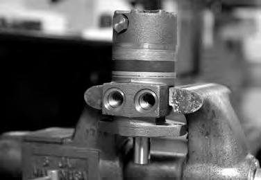
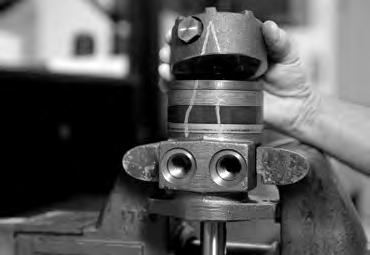
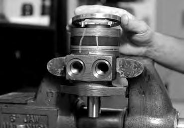
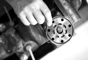
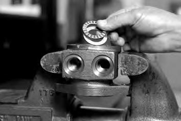
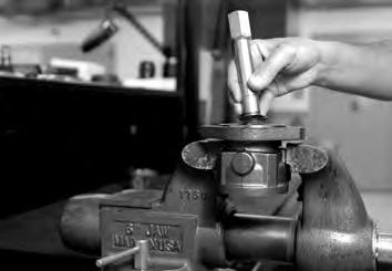
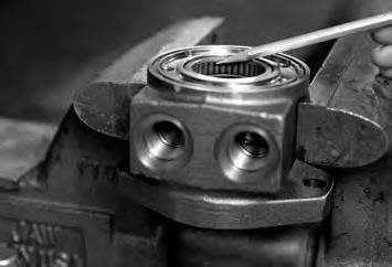
1. Place the Torqmotor™ in a soft jawed vise, with coupling shaft (10) pointed down and the vise jaws clamping frmly on the sides of the housing (17) mounting fange or port bosses. SEE FIGURE 3. Remove manifold port O-Rings (20) if applicable.
WARNING WARNING: IF THE TORQMOTOR™ IS NOT FIRMLY HELD IN THE VISE, IT COULD BE DISLODGED DURING THE SERVICE PROCEDURES, CAUSING INJURY.
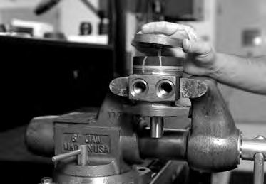
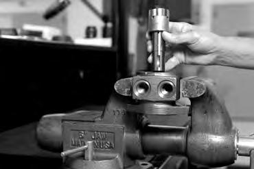
Scribe alignment mark & loosen valve plugs
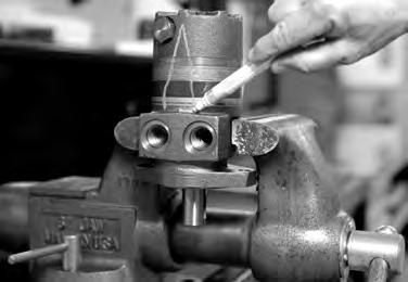
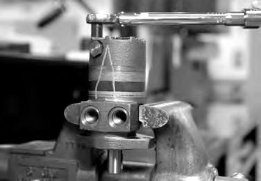
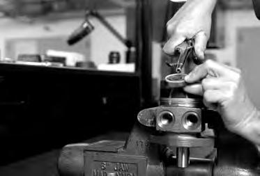
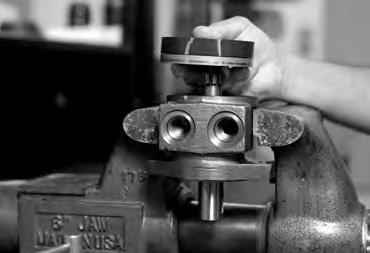
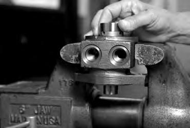
2. Scribe an alignment mark down and across the Torqmotor™ components from end cover (2) to housing (17) to facilitate reassembly orientation where required. Loosen two shuttle or relief valve plugs (21, 23) for disassembly later if included in end cover. 3/16 or 3/8 inch Allen wrench or 1 inch hex socket required. SEE FIGURES 4 & 5.
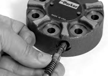
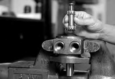
Remove special bolts & inspect bolts

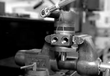
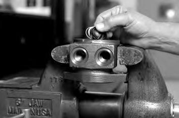
3. Remove the seven special ring head bolts (1, 1A, 1B or 1C) using an appropriate 1/2 inch size socket. Inspect bolts for damaged threads, or sealing rings, under the bolt head. Replace damaged bolts. SEE FIGURES 6-9.


28
Parker Hannifin Corporation Hydraulic Pump/Motor Division Greeneville, TN 37745 US
Figure 3
Figure 4
Figure 5
Figure 6
Figure 7
Figure 8
Figure 9
HY13-1526-001-M1/US
Disassembly and Inspection
Remove end cover & inspect bolts NOTE
Remove plugs and valves
Torqmotor™ Service Procedure

TC, TS, TB, TE and TJ Series
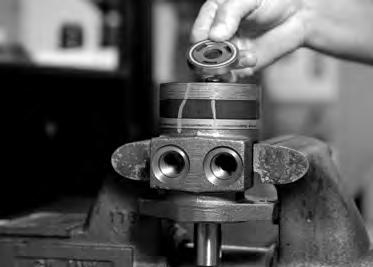
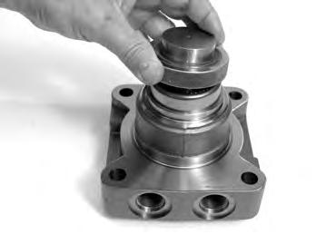
4. Remove end cover assembly (2). SEE FIGURE 10. After July 2012, motors no longer have section seal ring located in the end cover (2).
NOTE: Refer to the appropriate “alternate cover construction” on the exploded view to determine the end cover construction being serviced.
5. If the end cover (2) is equipped with shuttle valve or relief valve (22,24) components, remove the two previously loosened plugs (21,23). SEE FIGURE 11.
CAUTION NOTE NOTE
Wash & inspect end cover
CAUTION: Be ready to catch the shuttle valve or relief valve components that will fall out of the end cover valve cavity when the plugs are removed.
NOTE: O-ring (20) is not included in seal kits but serviced separately if required.
NOTE: The orifice plug in the end cover (2) must not be removed as they are serviced as an integral part of the end cover.
6. Thoroughly wash end cover (2) in proper solvent and blow dry. Be sure the end cover valve apertures, including the internal orifce plug, are free of contamination. Inspect end cover for cracks and the bolt head recesses for good bolt head sealing surfaces. Replace end cover as necessary.
NOTE
NOTE: A polished pattern (not scratches) on the cover from rotation of the commutator (5) is normal. Discoloration would indicate excess fluid temperature, thermal shock, or excess speed and require system investigation for cause and close inspection of end cover, commutator, manifold, and rotor set.
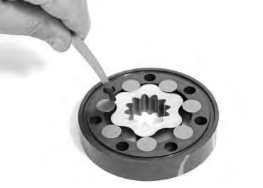
Remove & inspect commutator ring
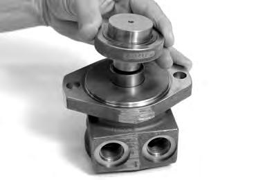
7. Remove commutator ring seal (3) and discard. SEE FIGURE 12. Remove commutator ring (5). Inspect commutator ring for cracks, or burrs. SEE FIGURE 13.
29
Parker Hannifin Corporation Hydraulic Pump/Motor Division Greeneville, TN 37745 US
Figure 13
Figure 12
Figure 11
Figure 10
HY13-1526-001-M1/US
Disassembly and Inspection
Remove & inspect commutator
Torqmotor™ Service Procedure
TC, TS, TB, TE and TJ Series
8. Remove commutator (5) and seal ring (4) Remove seal ring from commutator, using an air hose to blow air into ring groove until seal ring is lifted out and discard seal ring. Inspect commutator for cracks or burrs, wear, scoring, spalling or brinelling. If any of these conditions exist, replace commutator and commutator ring as a matched set.
SEE FIGURE 14 & 15.
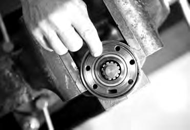
Remove manifold
9. Remove manifold seal ring (3) and discard. SEE FIGURE 16. Remove the manifold (6) and inspect for cracks surface scoring, brinelling or spalling. Replace manifold if any of these conditions exist. SEE FIGURE 17. A polished pattern on the ground surface from commutator or rotor rotation is normal.
NOTE NOTE: The manifold is constructed of plates bonded together to form an integral component not subject to further disassembly for service. Compare configuration of both sides of the manifold to ensure that same surface is reassembled against the rotor set.
30
Parker Hannifin Corporation Hydraulic Pump/Motor Division Greeneville, TN 37745 US
Figure 14
Figure 15
Figure 16
Figure 17
HY13-1526-001-M1/US
Disassembly and Inspection
Torqmotor™ Service Procedure


TC, TS, TB, TE and TJ Series
NOTE NOTE: A polished pattern on the wear plate from rotor rotation is normal. SEE FIGURE 18
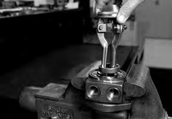
10. Remove rotor set (7) and wearplate (8), together to retain the rotor set in its assembled form, maintaining the same rotor vane to stator contact surfaces. SEE FIGURE 19. The drive link (9) may come away from the coupling shaft (10) with the rotor set, and wearplate. You may have to shift the rotor set on the wearplate to work the drive link out of the rotor (7) and wearplate (8). SEE FIGURE 20. Inspect the rotor set in its assembled form for nicks, scoring, or spalling on any surface and for broken or worn splines. If the rotor set component requires replacement, the complete rotor set must be replaced as it is a matched set. Inspect the wearplate for cracks, brinelling, or scoring. Discard seal ring (3) that is between the rotor set and wearplate.
NOTE NOTE: The rotor set (7) components may become disassembled during service procedures. Marking the surface of the rotor and stator that is facing UP, with etching ink or grease pencil before removal from Torqmotor™ will ensure correct reassembly of rotor into stator and rotor set into Torqmotor™. Marking all rotor components and mating spline components for exact repositioning at assembly will ensure maximum wear life and performance of rotor set and Torqmotor™.
Check rotor, vane clearance
11. Place rotor set (7) and wear plate (8) on a fat surface and center rotor in stator such that two rotor lobes (180 degrees apart) and a roller vane centerline are on the same stator centerline. Check the rotor lobe to roller vane clearance with a feeler gage at this common centerline. If there is more than .005 inches (0.13 mm) of clearance, replace rotor set. SEE FIGURE 21 & 22.
NOTE NOTE: If rotor set (7) has two stator halves and two sets of seven vanes, check the rotor lobe to roller vane clearance at both ends of rotor.
31
Parker Hannifin Corporation Hydraulic Pump/Motor Division Greeneville, TN 37745 US
Remove & inspect rotor set & wearplate
Figure 20
Figure 21
Figure 19
Figure 18
HY13-1526-001-M1/US
Disassembly and Inspection
Torqmotor™ Service Procedure

TC, TS, TB, TE and TJ Series
12. If wear plate is still in place then remove the wear plate seal ring (3) and discard.
Remove & inspect drive link
13. Remove drive link (9) from coupling shaft (10) if it was not removed with rotor set and wear plate. Inspect drive link for cracks and worn or damaged splines. No perceptible lash (play) should be noted between mating spline parts. SEE FIGURE 23.

Remove seal ring from housing
14. Remove and discard seal ring (3) from housing (17). SEE FIGURE 24.
Check coupling shaft for rust or corrosion
15. Check exposed portion of coupling shaft (10) to be sure you have removed all signs of rust and corrosion which might prevent its withdrawal through the seal and bearing. Crocus cloth or fne emery paper may be used. SEE FIGURE 25. Remove any key (26) or nut (27a,27b).
32
Parker Hannifin Corporation Hydraulic Pump/Motor Division Greeneville, TN 37745 US
Figure 25
Figure 24
Figure 23
Figure 22
HY13-1526-001-M1/US
Disassembly and Inspection
Remove & inspect coupling shaft
Torqmotor™ Service Procedure
TC, TS, TB, TE and TJ Series
16. Remove coupling shaft (10), by pushing on the output end of shaft. SEE FIGURE 26 & 27. Inspect coupling shaft bearing and seal surfaces for spalling, nicks, grooves, severe wear or corrosion and discoloration. Inspect for damaged or worn internal and external splines or keyway. SEE FIGURE 28. Replace coupling shaft if any of these conditions exist.
NOTE NOTE
Inspect housing assembly
NOTE: Minor shaft wear in seal area is permissible. If wear exceeds .020 inches (0.51 mm) diametrically, replace coupling shaft.
NOTE: A slight “polish” is permissible in the shaft bearing areas. Anything more would require coupling shaft replacement.
17. Inspect housing (17) assembly for cracks, the machined surfaces for nicks, burrs, brinelling or corrosion. Remove burrs that can be removed without changing dimensional characteristics. Inspect tapped holes for thread damage. SEE FIGURE 29. If the housing is defective in these areas, discard the housing assembly.
Remove & inspect thrust washer & thrust bearing
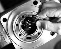
18. Remove thrust bearing (12) and thrust washer (13). Inspect for wear, brinelling, corrosion and a full complement of retained rollers. SEE FIGURE 30.
The TJ series has a thrust bearing (12) sandwiched between two thrust washers (13) that cannot be removed from the housing (17) unless bearing (14) is removed for replacement.

33
Parker Hannifin Corporation Hydraulic Pump/Motor Division Greeneville, TN 37745 US
Inspection Areas
Figure 26
Figure 27
Figure 28
Figure 29
Figure 30
HY13-1526-001-M1/US
Disassembly and Inspection
Remove shaft seal, backup ring and backup washer
Inspect housing bearing/bushing
Torqmotor™ Service Procedure
TC, TS, TB, TE and TJ Series
19. Remove shaft seal (14), backup washer (15) and back up ring (16) from housing (17). Discard both. SEE FIGURE 31.
In the TJ series, the shaft seal (14), backup washer (15) and backup ring (16) must be removed by working them around unseated thrust washers (13) and thrust bearing (12) and out of the housing. Discard seal and washers. SEE FIGURES 31A, 31B & 31C.
Remove bearings or bushings & thrust washers
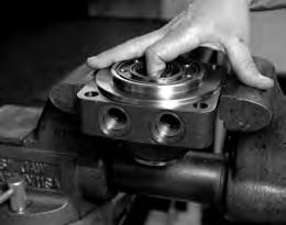
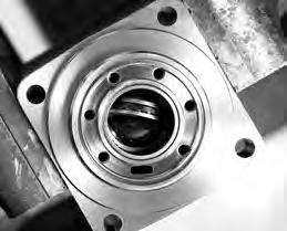
20. If the housing (17) assembly has passed inspection to this point, inspect the housing bearings/bushings (11) and (18) and if they are captured in the housing cavity the thrust washer (13) and thrust bearing (12). The bearing rollers must be frmly retained in the bearing cages, but must rotate and orbit freely. All rollers and thrust washers must be free of brinelling and corrosion. SEE FIGURE 32. A bearing, bushing, or thrust washer that does not pass inspection must be replaced. If the housing has passed this inspection the disassembly of the Torqmotor™ is completed.
21. If the bearings, bushing or thrust washers must be replaced use a suitable size bearing puller to remove bearing/bushings (18) and (11) from housing (17) without damaging the housing. Remove thrust washer (13) and thrust bearing (12) if they were previously retained in the housing by bearing (11). SEE FIGURES 33.
Remove dirt & water seal
22. Remove housing (17) from vise, invert it and remove and discard dirt & water seal (19). A blind hole bearing or seal puller is required. SEE FIGURE 34.
THE DISASSEMBLY OF TORQMOTOR™ IS COMPLETED.
34
Parker Hannifin Corporation Hydraulic Pump/Motor Division Greeneville, TN 37745 US
Figure 31
Figure 31A
Figure 31B
Figure 31C
Figure 32
Figure 33
Figure 34
HY13-1526-001-M1/US
Torqmotor™ Assembly
Torqmotor™ Service Procedure
TC, TS, TB, TE and TJ Series
• Replace all seals and seal rings with new ones each time you reassemble the Torqmotor™ unit. Lubricate all seals and seal rings with SAE 10W40 oil or clean grease before assembly.
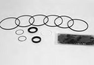
• NOTE: Individual seals and seal rings as well as a complete seal kit are available. SEE FIGURE 35. The parts should be available through most OEM parts distributors or Parker approved Torqmotor™ distributors. (Contact your local dealer for availability).
• NOTE: Unless otherwise indicated, do not oil or grease parts before assembly.
• Wash all parts in clean petroleum-based solvents before assembly. Blow them dry with compressed air. Remove any paint chips from mating surfaces of the end cover, commutator set, manifold rotor set, wear plate and housing and from port and sealing areas.
WARNING WARNING
WARNING: SINCE THEY ARE FLAMMABLE, BE EXTREMELY CAREFUL WHEN USING ANY SOLVENT. EVEN A SMALL EXPLOSION OR FIRE COULD CAUSE INJURY OR DEATH.
WARNING: WEAR EYE PROTECTION AND BE SURE TO COMPLY WITH OSHA OR OTHER MAXIMUM AIR PRESSURE REQUIREMENTS.
Press in outer bearing/bushing
1. If the housing (17) bearing components were removed for replacement, thoroughly coat and pack a new outer bearing/bushing (18) with clean corrosion resistant grease recommended in the material section. Press the new bearing/ bushing into the counterbore at the mounting fange end of the housing, using the appropriate sized bearing mandrel such as described in Figure 1 or Figure 2 which will control the bearing/ bushing depth.
TC, TS, TB and TE Torqmotor™ housings require the use of bearing mandrel shown in Figure 1 to press bearing/ bushing (18) into the housing to a required depth of .151/.161 inches (3.84/4.09 mm) from the end of the bearing counterbore. SEE FIGURE 36A.
TJ Torqmotor™ housings require the use of the bearing mandrel shown in Figure 2 to press bearing (18) into the housing to a required depth of .290/.310 inches (7.37/7,87 mm) from the outside end of the bearing counterbore. SEE FIGURE 36B.
35
Parker Hannifin Corporation Hydraulic Pump/Motor Division Greeneville, TN 37745 US
Figure 35 seal kit
Figure 36A
Figure 36B
3
19 16 15 14 4
HY13-1526-001-M1/US Torqmotor™ Service Procedure
Torqmotor™ Assembly
TC, TS, TB, TE and TJ Series
NOTE NOTE: Bearing mandrel must be pressed against the lettered end of bearing shell. Take care that the housing bore is square with the press base and the bearing/ bushing is not cocked when pressing a bearing/bushing into the housing.
CAUTION
CAUTION: If the bearing mandrel specified in the “Tools and Materials Required for Servicing” section is not available and alternate methods are used to press in bearing/bushing (11) and (18) the bearing/bushing depths specified must be achieved to insure adequate bearing support and correct relationship to adjacent components when assembled.
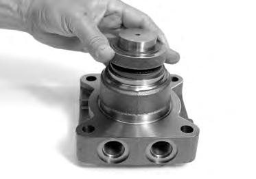
CAUTION
CAUTION: Because the bearing/bushings (11) and (18) have a press fit into the housing they must be discarded when removed. They must not be reused.
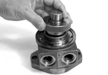
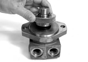
Press in dirt & water seal
2. Press a new dirt and water seal (19) into the housing (17) outer bearing counterbore. The dirt and water seal (19) must be pressed in until its’ fange is fush against the housing. SEE FIGURE 37A.
The TJ series dirt and water seal (19) must be pressed in the lip facing out and until the seal is fush to .020 inches (.51 mm) below the end housing. SEE FIGURE 37B.
Press in inner bearing/bushing
3. The inner housing bearing/bushing (11) can now be pressed into its counterbore in housing (17) fush to .03 inch (.76 mm) below the housing wear plate contact face. Use the opposite end of the bearing mandrel that was used to press in the outer bearing/bushing (18). Reference Figure 1, “Tools and Materials Required for Servicing” section. SEE FIGURE 38.
36
Parker Hannifin Corporation Hydraulic Pump/Motor Division Greeneville, TN 37745 US
Figure 37A
Figure 37B
Figure 38
HY13-1526-001-M1/US Torqmotor™ Service Procedure
Torqmotor™ Assembly
Place housing assembly into vise
Assemble
TC, TS, TB, TE and TJ Series
4. Place housing (17) assembly into a soft jawed vise with the coupling shaft bore down, clamping against the mounting fange. SEE FIGURE 39.
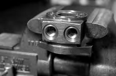
5. TC, TS, TB & TE Torqmotors™ assemble a new backup ring (16), new backup washer (15) and new seal (14) with the seal lip facing toward the inside of Torqmotor™ (see Figure 57B), into their respective counterbores in housing (17) if they were not assembled in procedure 1.
The TJ Torqmotor™ housing (17) requires that you assemble a new backup washer (15) & backup ring (16), new seal (14), with the lip facing to the inside of Torqmotor (see fgure 57A), new thrust washer (13), new thrust bearing (12) and a new second thrust washer (13) in that order before pressing in the inner housing bearing (11).
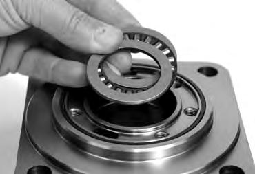
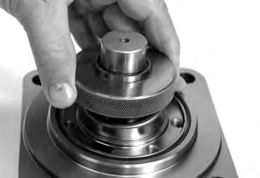


SEE FIGURES 40A & 40B.
When these components are in place, press new bearing (11) into the housing (17) to a depth of .03 inches (.76 mm) max for TJ below the housing wear plate contact face. Use the opposite end of the bearing mandrel used to press in outer bearing (18). Reference Figure 2, in the “Tools and Materials Required for Servicing” section.
SEE FIGURE 40C.
37
Parker Hannifin Corporation Hydraulic Pump/Motor Division Greeneville, TN 37745 US
Figure 39
Figure 40
Figure 40A
Figure 40C
Figure 40B
backup washer & seal
HY13-1526-001-M1/US
Torqmotor™ Assembly
Torqmotor™ Service Procedure

TC, TS, TB, TE and TJ Series
For a TJ Torqmotor™ that did not require replacing the bearing, assemble a new backup washer (15) & backup ring (16) and a new seal (14), with the lip facing to the inside of Torqmotor (see fgure 57A), by working them around unseated thrust washers (13) and thrust bearing (12).
SEE FIGURE 40D.
Assemble thrust washer & bearing
NOTE
6. Assemble thrust washer (13) then thrust bearing (12) that was removed from the Series TC, TB, TS or TE Torqmotor™.
SEE FIGURE 41.
NOTE: TC, TS, TB and TE Torqmotors™ require one thrust washer (13) with thrust bearing (12). The coupling shaft will be seated directly against the thrust bearing.
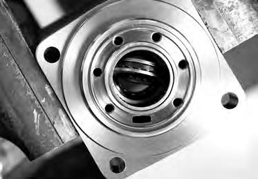

Install coupling shaft
7. Be sure that a generous amount of clean corrosion resistant grease has been applied to the lower (outer) housing bearing/bushing (18). Install the coupling shaft (10) into housing (17), seating it against the thrust bearing (12) in TC, TS, TB and TE Series housings.
SEE FIGURE 42.
CAUTION
CAUTION: The outer bearing (18) is not lubricated by the system’s hydraulic fluid. Be sure it is thoroughly packed with the recommended grease, Parker Gear grease specification #045236, E/M Lubricant #K-70M.
NOTE
NOTE: Mobil Mobilith SHC ® 460 NOTE: A 102 Tube (P/N 406010) is included in each seal kit.
NOTE NOTE: The coupling shaft (10) will be flush or just below the housing wear surface on the TC, TS, TB, TE & TJ Torqmotors™ when properly seated. The coupling shaft must rotate smoothly on the thrust bearing package.
38
Parker Hannifin Corporation Hydraulic Pump/Motor Division Greeneville, TN 37745 US
Figure 42
Figure 41
Figure 40D
HY13-1526-001-M1/US Torqmotor™ Service Procedure
Torqmotor™ Assembly
TC, TS, TB, TE and TJ Series
Insert seal ring 8. Apply a small amount of clean grease to a new seal ring (3) and insert it into the housing (17) seal ring groove. SEE FIGURE 43.
Install drive link
9. Install drive link (9) the long splined end down into the coupling shaft (10) and engage the drive link splines into mesh with the coupling shaft splines. SEE FIGURE 44.
NOTE
NOTE: Use any alignment marks put on the coupling shaft and drive link before disassembly to assemble the drive link splines in their original position in the mating coupling shaft splines.

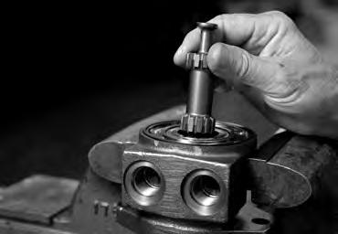
NOTE
NOTE: One or two alignment studs screwed finger tight into housing (17) bolt holes, approximately 180 degrees apart, will facilitate the assembly and alignment of components as required in the following procedures. The studs can be made by cutting off the heads of either 3/8-24 UNF 2A or 5/16-24 UNF 2A bolts as required that are over .5 inch (12.7 mm) longer than the bolts (1, 1A, 1B or 1C) used in the Torqmotor™.
Assemble wear plate
10. Assemble wear plate (8) over the drive link (9) and alignment studs onto the housing (17). SEE FIGURE 45.
Apply a small amount of clean grease to a new seal ring and insert into the groove of the wear plate.

39
Parker Hannifin Corporation Hydraulic Pump/Motor Division Greeneville, TN 37745 US
Figure 43
Figure 44
Figure 45
HY13-1526-001-M1/US Torqmotor™ Service Procedure
Torqmotor™ Assembly
Install the assembled rotor set
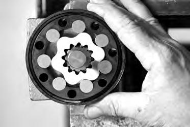
TC, TS, TB, TE and TJ Series
11. Install the assembled rotor set (7) onto wear plate (8) with rotor counterbore and seal ring side down and the splines into mesh with the drive link splines.
Apply clean grease to a new seal ring (3) and assemble it in the seal ring groove in the rotor set.
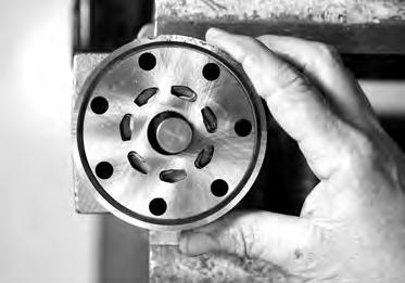
NOTE NOTE: It may be necessary to turn one alignment stud out of the housing (17) temporarily to assemble rotor set (7) or manifold (6) over the drive link.
NOTE NOTE: If necessary, go to the appropriate, “Rotor Set Component Assembly Procedure.”
NOTE NOTE: The rotor set rotor counterbore side must be down against wear plate for drive link clearance and to maintain the original rotor-drive link spline contact. A rotor set without a counterbore and that was not etched before disassembly can be reinstalled using the drive link spline pattern on the rotor splines if apparent, to determine which side was down.
Assemble manifold
12. Assemble the manifold (6) over the alignment studs and drive link (9) and onto the rotor set. Be sure the correct manifold surface is against the rotor set.
Apply grease to a new seal ring (3) and insert it in the seal ring groove exposed on the manifold. SEE FIGURE 47.
NOTE: The manifold (6) is made up of several plates bonded together permanently to form an integral component. The manifold surface that must contact the rotor set has it’s series of irregular shaped cavities on the largest circumference or circle around the inside diameter. The polished impression left on the manifold by the rotor set is another indication of which surface must contact the rotor set.
40
Parker Hannifin Corporation Hydraulic Pump/Motor Division Greeneville, TN 37745 US
Figure 46
Figure 47
HY13-1526-001-M1/US
Torqmotor™ Assembly
Assemble commutator ring
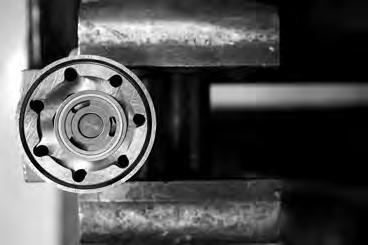
Torqmotor™ Service Procedure
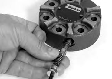
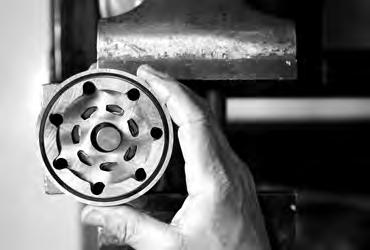
TC, TS, TB, TE and TJ Series
13. Assemble the commutator ring (5) over alignment studs onto the manifold. SEE FIGURE 48. After June 2012, add seal ring to commutator ring.
Assemble seal & commutator
14. Assemble a new commutator seal ring (3) fat side up, into commutator (5) and assemble commutator over the end of drive link (9) onto manifold (6) with seal ring side up. SEE FIGURE 49.
Assemble shuttle valve parts into end cover
15. If shuttle valve components items #23, #24, #25 were removed from the end cover (2) turn a plug (23) with a new o-ring (20), loosely into one end of the valve cavity in the end cover. Insert a spring (25) the valve (24) and the second spring (25) into the other end of the valve cavity. Turn the second plug (23) with a new o-ring (20) loosely into the end cover valve cavity. 3/16 inch Allen wrench required. SEE FIGURE 50.
41
Parker Hannifin Corporation Hydraulic Pump/Motor Division Greeneville, TN 37745 US
Figure 48
Figure 49
Figure 50
HY13-1526-001-M1/US
Torqmotor™ Assembly
Assemble relief valve parts in end cover
Torqmotor™ Service Procedure
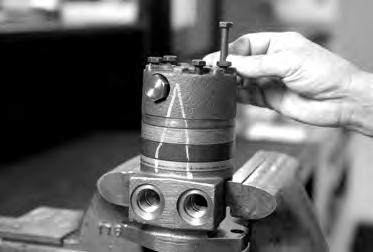
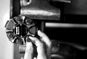
TC, TS, TB, TE and TJ Series
16. If relief valve components items #21, #22 were removed from the end cover (2) assemble a new o-ring (20) on the two plugs (21). Assemble a two piece relief valve (22) in each of the plugs, with the large end of the conical spring into the plug frst and the small nut of the other valve piece in the small end of the conical spring. Turn each of the plug and relief valve assemblies into the end cover loosely to be torqued later. 3/8 inch Allen or 1 inch Hex socket required. SEE FIGURE 51 & 52.
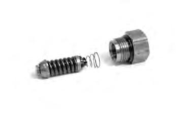
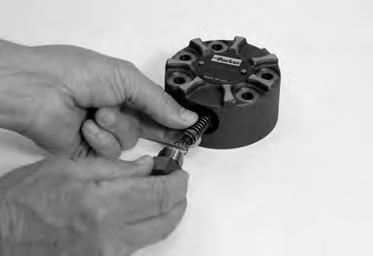
Assemble end cover
17. Assemble end cover over the alignment studs and onto the commutator set. SEE FIGURE 53 & 54. If the end cover has only 5 bolt holes be sure the cover holes are aligned with the 5 threaded holes in housing (17). The correct 5 bolt end cover bolt hole relationship to housing port bosses is shown in FIGURE 53. After June 2012, end cover no longer has o-ring section seal.
NOTE
NOTE: If the end cover has a valve (22, 24) or has five bolt holes, use the line you previously scribed on the cover to radially align the end cover into its original position.
42
Parker Hannifin Corporation Hydraulic Pump/Motor Division Greeneville, TN 37745 US
Figure 52
Figure 53
Figure 54
Figure 51
HY13-1526-001-M1/US
Torqmotor™ Assembly
Assemble cover bolts
Torqmotor™ Service Procedure
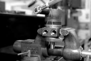
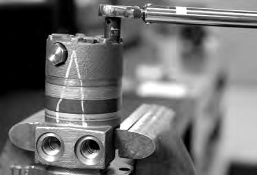
TC, TS, TB, TE and TJ Series
18. Assemble the 5 or 6 special bolts (1, 1A, 1B or 1C) and screw in fnger tight. Remove and replace the two alignment studs with bolts after the other bolts are in place. Alternately and progressively tighten the bolts to pull the end cover and other components into place with a fnal torque of 25-30 ft. lbs. (34-41 N m) for the fve TC, TS, TB or six TE Series 5/16 24 threaded bolts or six TJ bolts. SEE FIGURE 55.
NOTE NOTE: The special bolts required for use with the relief or shuttle valve (22, 24) end cover assembly (2) are longer than the bolts required with standard and cover assembly. Refer to the individual service parts lists or parts list charts for correct service part number if replacement is required.
Torque the valve plugs
19. Torque the two shuttle valve plug assemblies (23) in end cover assembly to 9-12 ft. lbs. (12-16 N m) if cover is so equipped. SEE FIGURE 56.
Torque the two relief valve plug assemblies (21) in end cover assembly to 45-55 ft. lbs. (61-75 N m) if cover is so equipped.
43
Parker Hannifin Corporation Hydraulic Pump/Motor Division Greeneville, TN 37745 US
Figure 55
Figure 56
HY13-1526-001-M1/US
Torqmotor™ Assembly
Torqmotor™ Service Procedure
TC, TS, TB, TE and TJ Series
THE ASSEMBLY OF THE TORQMOTOR™ IS NOW COMPLETE EXCEPT FOR WOODRUFF KEY, NUT, WASHER, BOLT, LOCKWASHER, RETAINER RING or PORT O-RINGS AT INSTALLATION IF APPLICABLE. PROCEED TO FINAL CHECKS SECTION.
Parker
Corporation Hydraulic
44
Hannifin
Pump/Motor Division Greeneville, TN 37745 US
Housing Thrust Washers Seal Shaft Thrust Bearing Backup W Steel Washer asher Not To Scale
Figure 57B TC, TS, TB, TE Series
TJ
Housing Thrust Washers Seal Shaft Thrust Bearing Backup Washer Steel Washer Not To Sc ale
Figure 57A
Series
HY13-1526-001-M1/US
Rotor Set Component Assembly
One Piece Stator Construction
Torqmotor™ Service Procedure
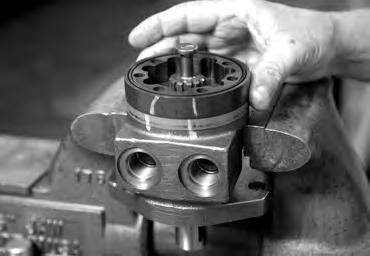
TC, TS, TB, TE and TJ Series
A disassembled rotor (7) stator and vanes that cannot be readily assembled by hand can be assembled by the following procedures.
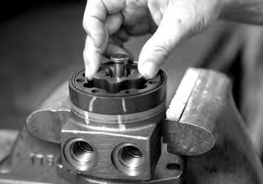

Assemble stator 1. Place stator (7) onto wear plate (8) with seal ring (3) side up, after following Torqmotor™ assembly procedures 1 through 11. Be sure the seal ring is in place. SEE FIGURE 58.
Insert two bolts
2. If assembly alignment studs are not being utilized, align stator bolt holes with wear plate and housing bolt holes and turn two bolts (1, 1A, 1B or 1C) fnger tight into bolt holes approximately 180 degrees apart to retain stator and wear plate stationary.
Assemble rotor 3. Assemble the rotor (7), counterbore down if applicable, into stator, and onto wear plate (8) with rotor splines into mesh with drive link (9) splines. SEE FIGURE 59.
NOTE NOTE: If the manifold side of the rotor was etched during Torqmotor disassembly, this side should be up. If the rotor is not etched and does not have a counterbore, use the drive link spline contact pattern apparent on the rotor splines to determine the rotor side that must be against the wear plate.
Assemble vanes
4. Assemble six vanes, or as many vanes that will readily assemble into the stator vane pockets. SEE FIGURE 60.
CAUTION
Assemble full complement of vanes
CAUTION: Excessive force used to push the rotor vanes into place could shear off the coating applied to the stator vane pockets.
5. Grasp the output end of coupling shaft (10) with locking pliers or other appropriate turning device and rotate coupling shaft, drive link and rotor to seat the rotor and the assembled vanes into stator, creating the necessary clearance to assemble the seventh or full complement of seven vanes. Assemble the seven vanes using minimum force.
Remove two assembled bolts
6. Remove the two assembled bolts (1, 1A, 1B or 1C) if used to retain stator and wear plate.
Go to Torqmotor™ assembly procedure #13, to continue Torqmotor™ assembly.
Parker Hannifin Corporation Hydraulic Pump/Motor Division Greeneville, TN 37745 US
45
Figure 60
Figure 59
Figure 58
HY13-1526-001-M1/US Torqmotor™ Service Procedure
Rotor Set Component Assembly
Two Piece Stator Construction
TC, TS, TB, TE and TJ Series
A disassembled rotor set (7) that cannot be readily assembled by hand and has a two piece stator can be assembled by the following procedures.
Assemble stator halves
Insert two alignment studs
1. Place stator half onto wear plate (8) with seal ring (3) side up, after following Torqmotor™ assembly procedures 1 through 11. Be sure the seal ring is in place. SEE FIGURE 61.
2. Align stator bolt holes with wear plate and housing bolts and turn two alignment studs fnger tight into bolt holes approximately 180 degrees apart to retain stator half and wear plate stationary. SEE FIGURE 46.
Assemble rotor NOTE
3. Assemble rotor, counterbore down into stator half, and onto wear plate (8) with rotor splines into mesh with drive link (9) splines.
NOTE: Use any marking you applied to rotor set components to reassemble the components in their original relationship to ensure ultimate wear life and performance.
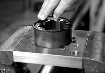

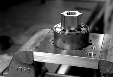
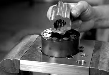
Assemble vanes
CAUTION
4. Assemble six vanes, or as many vanes that will readily assemble into the stator vane pockets. SEE FIGURE 62.
CAUTION: Excessive force used to push the rotor vanes into place could shear off the coating applied to the stator vane pockets.
Assemble full complement of vanes
5. Grasp the output end of coupling shaft (10) with locking pliers or other appropriate turning device and rotate coupling shaft, drive link and rotor to seat the rotor and the assembled vanes into stator half, creating the necessary clearance to assemble the seventh or full complement of seven vanes. Assemble the seven vanes using minimum force. SEE FIGURE 60.
Assemble seal ring in stator half
6. Place second stator half on a fat surface with seal ring groove up. Apply a small amount of grease to a new seal ring (3) and assemble it into stator half ring groove.
46
Parker Hannifin Corporation Hydraulic Pump/Motor Division Greeneville, TN 37745 US
Figure 63
Figure 64
Figure 62
Figure 61
HY13-1526-001-M1/US
Rotor Set Component Assembly
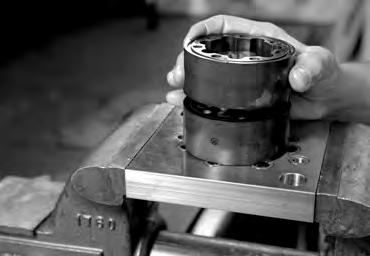
Assemble second stator half
Torqmotor™ Service Procedure
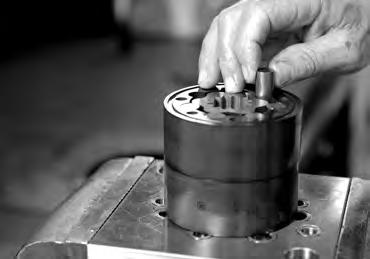
TC, TS, TB, TE and TJ Series
7. Assemble the second stator half over the two alignment studs and rotor with seal ring side up onto the frst stator half aligning any timing marks applied for this purpose. SEE FIGURE 65.

CAUTION
CAUTION: If the stator half is a different height (thickness) than stator half the stator vanes or of the same length (height) as the stator half must be reassembled in their respective stator half for the rotor set to function properly.
Assemble vanes
Assemble full complement of vanes
8. Assemble six vanes, or as many vanes that will readily assemble into the stator vane pockets. SEE FIGURE 66.
9. Grasp the output end of coupling shaft (10) with locking pliers or other appropriate turning device and rotate coupling shaft, drive link and rotor to seat the rotor and the assembled vanes into stator, creating the necessary clearance to assemble the seventh or full complement of seven vanes. Assemble the seven vanes using minimum force. SEE FIGURE 60.
Go to Torqmotor™ assembly procedure #13, to continue Torqmotor™ assembly.
47
Parker Hannifin Corporation Hydraulic Pump/Motor Division Greeneville, TN 37745 US
Figure 67
Figure 66
Figure 65
HY13-1526-001-M1/US
Final Checks
Final Checks
Torqmotor™ Service Procedure
TC, TS, TB, TE and TJ Series
• Pressurize the Torqmotor™ with 100 p.s.i. dry air or nitrogen and submerge in solvent to check for external leaks.
• Check Torqmotor™ for rotation. Torque required to rotate coupling shaft should not be more than 50 ft. lbs. (68 N m)
• Pressure port with “A” cast under it on housing (17) is for clockwise coupling shaft rotation as viewed from the output end of coupling shaft. Pressure port with “B” cast under it is for counter clockwise coupling shaft rotation.
• Use test stand if available, to check operation of the Torqmotor™.
Hydraulic Fluid
Keep the hydraulic system flled with one of the following:
• 10W40 SE or SF manufacturers suggested oil.
• Hydraulic fuid as recommended by equipment manufacturer, but the viscosity should not drop below 50 SSU or contain less than .125% zinc anti-wear additives.
CAUTION: Do not mix oil types. Any mixture, or an unapproved oil, could deteriorate the seals. Maintain the proper fluid level in the reservoir. When changing fluid, completely drain old oil from the system. It is suggested also that you flush the system with clean oil.
Parker Hannifin Corporation Hydraulic Pump/Motor Division Greeneville, TN 37745 US
48
Filtration
fltration 40-50 micron. Oil Temperature Maximum operating temperature 200°F (93.3° C).
Recommended
HY13-1526-001-M1/US Torqmotor™ Service Procedure
Tips
TS, TB, TE and TJ Series
Tips for Maintaining the Torqmotor™ Hydraulic System
• Adjust fuid level in reservoir as necessary.
• Encourage all operators to report any malfunction or accident that may have damaged the hydraulic system or component.
• Do not attempt to weld any broken Torqmotor™ component. Replace the component with original equipment only.
• Do not cold straighten, hot straighten, or bend any Torqmotor™ part.
• Prevent dirt or other foreign matter from entering the hydraulic system. Clean the area around and the fller caps before checking oil level.
• Investigate and correct any external leak in the hydraulic system, no matter how minor the leak.
• Comply with manufacturer’s specifcations for cleaning or replacing the flter.
CAUTION: Do not weld, braze, solder or any way alter any Torqmotor™ component.
CAUTION: Maximum operating pressure must not exceed recommended Torqmotor™ pressure capacity.
CAUTION: Always carefully inspect any system component that may have been struck or damaged during operation or in an accident. Replace any component that is damaged or that is questionable.
CAUTION: Do not force any coupling onto the Torqmotor™ coupling shaft as this could damage the unit internally.
Parker extends close technical cooperation and assistance. If problems occur which you cannot solve, please contact your local Parker approved Distributor or Parker Technical Support. Our phone number and fax number and address are on the back cover of this manual.
49
TC,
Parker Hannifin Corporation Hydraulic Pump/Motor Division Greeneville, TN 37745 US
HY13-1526-001-M1/US
Torqmotor™ Service Procedure
TC, TS, TB, TE and TJ Series
50
Parker Hannifin Corporation Hydraulic Pump/Motor Division Greeneville, TN 37745 US
Notes
HY13-1526-001-M1/US
Offer of Sale
Torqmotor™ Service Procedure
TC, TS, TB, TE and TJ Series
The items described in this document and other documents and descriptions provided by Parker Hannifn Corporation, its subsidiaries and its authorized distributors (“Seller”) are hereby offered for sale at prices to be established by Seller. This offer and its acceptance by any customer (“Buyer”) shall be governed by all of the following Terms and Conditions. Buyer’s order for any item described in its document, when communicated to Seller verbally, or in writing, shall constitute acceptance of this offer. All goods, services or work described will be referred to as “Products”.
1. Terms and Conditions. Seller’s willingness to offer Products, or accept an order for Products, to or from Buyer is subject to these Terms and Conditions or any newer version of the terms and conditions found on-line at www.parker.com/saleterms/. Seller objects to any contrary or additional terms or conditions of Buyer’s order or any other document issued by Buyer.
2. Price Adjustments; Payments. Prices stated on Seller’s quote or other documentation offered by Seller are valid for 30 days, and do not include any sales, use, or other taxes unless specifcally stated. Unless otherwise specifed by Seller, all prices are F.C.A. Seller’s facility (INCOTERMS 2010). Payment is subject to credit approval and is due 30 days from the date of invoice or such other term as required by Seller’s Credit Department, after which Buyer shall pay interest on any unpaid invoices at the rate of 1.5% per month or the maximum allowable rate under applicable law.
3. Delivery Dates; Title and Risk; Shipment. All delivery dates are approximate and Seller shall not be responsible for any damages resulting from any delay. Regardless of the manner of shipment, title to any products and risk of loss or damage shall pass to Buyer upon placement of the products with the shipment carrier at Seller’s facility. Unless otherwise stated, Seller may exercise its judgment in choosing the carrier and means of delivery. No deferment of shipment at Buyers’ request beyond the respective dates indicated will be made except on terms that will indemnify, defend and hold Seller harmless against all loss and additional expense. Buyer shall be responsible for any additional shipping charges incurred by Seller due to Buyer’s acts or omissions.
4. Warranty. Seller warrants that the Products sold hereunder shall be free from defects in material or workmanship for a period of eighteen months from the date of delivery to Buyer or 2,000 hours of normal use, whichever occurs frst. The prices charged for Seller’s products are based upon the exclusive limited warranty stated above, and upon the following disclaimer: DISCLAIMER OF WARRANTY: THIS WARRANTY COMPRISES THE SOLE AND ENTIRE WARRANTY PERTAINING TO PRODUCTS PROVIDED HEREUNDER. SELLER DISCLAIMS ALL OTHER WARRANTIES, EXPRESS AND IMPLIED, INCLUDING DESIGN, MERCHANTABILITY AND FITNESS FOR A PARTICULAR PURPOSE.
5. Claims; Commencement of Actions. Buyer shall promptly inspect all Products upon delivery. No claims for shortages will be allowed unless reported to the Seller within 10 days of delivery. No other claims against Seller will be allowed unless asserted in writing within 30 days after delivery. Buyer shall notify Seller of any alleged breach of warranty within 30 days after the date the defect is or should have been discovered by Buyer. Any action based upon breach of this agreement or upon any other claim arising out of this sale (other than an action by Seller for an amount due on any invoice) must be commenced within 12 months from the date of the breach without regard to the date breach is discovered.
6. LIMITATION OF LIABILITY. UPON NOTIFICATION, SELLER WILL, AT ITS OPTION, REPAIR OR REPLACE A DEFECTIVE PRODUCT, OR REFUND THE PURCHASE PRICE. IN NO EVENT SHALL SELLER BE LIABLE TO BUYER FOR ANY SPECIAL, INDIRECT, INCIDENTAL OR CONSEQUENTIAL DAMAGES ARISING OUT OF, OR AS THE RESULT OF, THE SALE, DELIVERY, NON-DELIVERY, SERVICING, USE OR LOSS OF USE OF THE PRODUCTS OR ANY PART THEREOF, OR FOR ANY CHARGES OR EXPENSES OF ANY NATURE INCURRED WITHOUT SELLER’S WRITTEN CONSENT, EVEN IF SELLER HAS BEEN NEGLIGENT, WHETHER IN CONTRACT, TORT OR OTHER LEGAL THEORY. IN NO EVENT SHALL SELLER’S LIABILITY UNDER ANY CLAIM MADE BY BUYER EXCEED THE PURCHASE PRICE OF THE PRODUCTS.
7. User Responsibility. The user, through its own analysis and testing, is solely responsible for making the fnal selection of the system and Product and assuring that all performance, endurance, maintenance, safety and warning requirements of the application are met. The user must analyze all aspects of the application and follow applicable industry standards and Product information. If Seller provides Product or system options, the user is responsible for determining that such data and specifcations are suitable and suffcient for all applications and reasonably foreseeable uses of the Products or systems.
8. Loss to Buyer’s Property. Any designs, tools, patterns, materials, drawings, confdential information or equipment furnished by Buyer or any other items which become Buyer’s property, will be considered obsolete and may be destroyed by Seller after two consecutive years have elapsed without Buyer ordering the items manufactured using such property. Seller shall not be responsible for any loss or damage to such property while it is in Seller’s possession or control.
9. Special Tooling. A tooling charge may be imposed for any special tooling, including without limitation, dies, fxtures, molds and patterns, acquired to manufacture Products. Such special tooling shall be and remain Seller’s property notwithstanding payment of any charges by Buyer. In no event will Buyer acquire any interest in apparatus belonging to Seller which is utilized in the manufacture of the Products, even if such apparatus has been specially converted or adapted for such manufacture and notwithstanding any charges paid by Buyer. Unless otherwise agreed, Seller shall have the right to alter, discard or otherwise dispose of any special tooling or other property in its sole discretion at any time.
10. Buyer’s Obligation; Rights of Seller. To secure payment of all sums due or otherwise, Seller shall retain a security interest in the goods delivered and this agreement shall be deemed a Security Agreement under the Uniform Commercial Code. Buyer authorizes Seller as its attorney to execute and fle on Buyer’s behalf all documents Seller deems necessary to perfect its security interest.
11. Improper use and Indemnity. Buyer shall indemnify, defend, and hold Seller harmless from any claim, liability, damages, lawsuits, and costs (including attorney fees), whether for personal injury, property damage, patent, trademark or copyright infringe-
ment or any other claim, brought by or incurred by Buyer, Buyer’s employees, or any other person, arising out of: (a) improper selection, improper application or other misuse of Products purchased by Buyer from Seller; (b) any act or omission, negligent or otherwise, of Buyer; (c) Seller’s use of patterns, plans, drawings, or specifcations furnished by Buyer to manufacture Product; or (d) Buyer’s failure to comply with these terms and conditions. Seller shall not indemnify Buyer under any circumstance except as otherwise provided.
12. Cancellations and Changes. Orders shall not be subject to cancellation or change by Buyer for any reason, except with Seller’s written consent and upon terms that will indemnify, defend and hold Seller harmless against all direct, incidental and consequential loss or damage. Seller may change product features, specifcations, designs and availability with notice to Buyer.
13. Limitation on Assignment. Buyer may not assign its rights or obligations under this agreement without the prior written consent of Seller.
14. Force Majeure. Seller does not assume the risk and shall not be liable for delay or failure to perform any of Seller’s obligations by reason of circumstances beyond the reasonable control of Seller (hereinafter “Events of Force Majeure”). Events of Force Majeure shall include without limitation: accidents, strikes or labor disputes, acts of any government or government agency, acts of nature, delays or failures in delivery from carriers or suppliers, shortages of materials, or any other cause beyond Seller’s reasonable control.
15. Waiver and Severability. Failure to enforce any provision of this agreement will not waive that provision nor will any such failure prejudice Seller’s right to enforce that provision in the future. Invalidation of any provision of this agreement by legislation or other rule of law shall not invalidate any other provision herein. The remaining provisions of this agreement will remain in full force and effect.
16. Termination. Seller may terminate this agreement for any reason and at any time by giving Buyer thirty (30) days written notice of termination. Seller may immediately terminate this agreement, in writing, if Buyer: (a) commits a breach of any provision of this agreement (b) appointments a trustee, receiver or custodian for all or any part of Buyer’s property (c) fles a petition for relief in bankruptcy on its own behalf, or by a third party (d) makes an assignment for the beneft of creditors, or (e) dissolves or liquidates all or a majority of its assets.
17. Governing Law. This agreement and the sale and delivery of all Products hereunder shall be deemed to have taken place in and shall be governed and construed in accordance with the laws of the State of Ohio, as applicable to contracts executed and wholly performed therein and without regard to conficts of laws principles. Buyer irrevocably agrees and consents to the exclusive jurisdiction and venue of the courts of Cuyahoga County, Ohio with respect to any dispute, controversy or claim arising out of or relating to this agreement.
18. Indemnity for Infringement of Intellectual Property Rights. Seller shall have no liability for infringement of any patents, trademarks, copyrights, trade dress, trade secrets or similar rights except as provided in this Section. Seller will defend and indemnify Buyer against allegations of infringement of U.S. patents, U.S. trademarks, copyrights, trade dress and trade secrets (“Intellectual Property Rights”). Seller will defend at its expense and will pay the cost of any settlement or damages awarded in an action brought against Buyer based on an allegation that a Product sold pursuant to this Agreement infringes the Intellectual Property Rights of a third party. Seller’s obligation to defend and indemnify Buyer is contingent on Buyer notifying Seller within ten (10) days after Buyer becomes aware of such allegations of infringement, and Seller having sole control over the defense of any allegations or actions including all negotiations for settlement or compromise. If a Product is subject to a claim that it infringes the Intellectual Property Rights of a third party, Seller may, at its sole expense and option, procure for Buyer the right to continue using the Product, replace or modify the Product so as to make it noninfringing, or offer to accept return of the Product and return the purchase price less a reasonable allowance for depreciation. Notwithstanding the foregoing, Seller shall have no liability for claims of infringement based on information provided by Buyer, or directed to Products delivered hereunder for which the designs are specifed in whole or part by Buyer, or infringements resulting from the modifcation, combination or use in a system of any Product sold hereunder. The foregoing provisions of this Section shall constitute Seller’s sole and exclusive liability and Buyer’s sole and exclusive remedy for infringement of Intellectual Property Rights.
19. Entire Agreement. This agreement contains the entire agreement between the Buyer and Seller and constitutes the fnal, complete and exclusive expression of the terms of sale. All prior or contemporaneous written or oral agreements or negotiations with respect to the subject matter are herein merged.
20. Compliance with Law, U.K. Bribery Act and U.S. Foreign Corrupt Practices Act. Buyer agrees to comply with all applicable laws and regulations, including both those of the United Kingdom and the United States of America, and of the country or countries of the Territory in which Buyer may operate, including without limitation the U. K. Bribery Act, the U.S. Foreign Corrupt Practices Act (“FCPA”) and the U.S. Anti-Kickback Act (the “Anti-Kickback Act”), and agrees to indemnify and hold harmless Seller from the consequences of any violation of such provisions by Buyer, its employees or agents. Buyer acknowledges that they are familiar with the provisions of the U. K. Bribery Act, the FCPA and the Anti-Kickback Act, and certifes that Buyer will adhere to the requirements thereof. In particular, Buyer represents and agrees that Buyer shall not make any payment or give anything of value, directly or indirectly to any governmental offcial, any foreign political party or offcial thereof, any candidate for foreign political offce, or any commercial entity or person, for the purpose of infuencing such person to purchase products or otherwise beneft the business of Seller.
2/12
Parker Hannifin Corporation Hydraulic Pump/Motor Division Greeneville, TN 37745 US 51
Parker Hannifin Corporation 2745 Snapps Ferry Road Greeneville, TN 37745 USA Tel: (423) 639-8151 FAX: (423) 787-2418 www.parker.com/pumpmotor
