Servomotors EX Series

Technical Manual

PVD 3665 - EX


1 – PVD3665 GB EX July 2016.Docx
2 – PVD3665 GB EX July 2016.Docx
3 – PVD3665 GB EX July 2016.Docx

Technical Manual
PVD 3665 - EX
This manual contains information that must be observed to select, install, operate and maintain PARKER EX servomotors


Installation, operation and maintenance of the equipment should be carried out by qualified personnel. A qualified person is someone who is technically competent and familiar with all safety information and established safety practices; with the installation process, operation and maintenance of this equipment; and with all the hazards involved.

Reading and understanding the information described in this document is mandatory before carrying out any operation on the motors. If any malfunction or technical problem occurs, that has not been dealt with in this manual, please contact PARKER for technical assistance. In case of missing information or doubts regarding the installation procedures, safety instructions or any other issue tackled in this manual, please contact PARKER as well.
PARKER’s responsibility is limited to its servomotors and does not encompass the whole user’s system. Data provided in this manual are for product description only and may not be guaranteed, unless expressly mentioned in a contract.
DANGER: PARKER declines responsibility for any accident or material damage that may arise, if the procedures and safety instructions described in this manual are not scrupulously followed.

Motors for ATEX zones : Servomotors type EX manufactured for the European market are designed to operate in ATEX classified zones
Motors for hazardous classified locations : EX servomotors manufactured for the North American market are designed to operate in harzardous classified areas.
Motors for Ex zones : Servomotors type EX manufactured off European and North American markets are designed to operate in Ex classified zones.
To operate safely, this equipment must be transported, stored, handled, installed and serviced correctly. Following the safety instructions described in each section of this document is mandatory. Servomotors usage must also comply with all applicable standards, national directives and factory instructions in force.
DANGER: Non-compliance with safety instructions, legal and technical regulations in force may lead to physical injuries or death, as well as damages to the property and the environment.
DANGER: The installation, commission and operation must be performed by qualified personnel, in conjunction with this documentation.
The qualified personnel must know the safety (C18510 authorization, standard VDE 0105 or IEC 0364) and local regulations.
They must be authorized to install, commission and operate in accordance with established practices and standards.
Electrical hazard

Servo drives may contain non-insulated live AC or DC components. Respect the drives commissioning manual. Users are advised to guard against access to live parts before installing the equipment.
Some parts of the motor or installation elements can be subjected to dangerous voltages, when the motor is driven by the inverter , when the motor rotor is manually rotated, when the motor is driven by its load, when the motor is at standstill or stopped.
For measurements use only a meter to IEC 61010 (CAT III or higher). Always begin using the highest range. CAT I and CAT II meters must not be used on this product.
Allow at least 5 minutes for the drive's capacitors to discharge to safe voltage levels (<50V). Use the specified meter capable of measuring up to 1000V dc & ac rms to confirm that less than 50V is present between all power terminals and between power terminals and earth.
Check the drive recommendations.
The motor must be permanently connected to an appropriate safety earth. To prevent any accidental contact with live components, it is necessary to check that cables are not damaged, stripped or not in contact with a rotating part of the machine. The work place must be clean, dry.
General recommendations :
- Check the wiring circuit
- Lock the electrical cabinets
- Use standardized equipment
Servomotors can accelerate in milliseconds. Running the motor can lead to other sections of the machine moving dangerously. Moving parts must be screened off to prevent operators coming into contact with them. The working procedure must allow the operator to keep well clear of the danger area.
Always bear in mind that some parts of the surface of the motor can reach a temperature of 135°C.
The installation and operation must be made with the Commissioning and use manual given with the motor.
Commissioning and use manual of the EX motor series : - EX8 Atex : PVD 3571
This motor can be used in hazardous areas. May particular attention to the notes marked with .
European directive 99/92/EC makes explicit the responsibility of employers to protect employees who may be exposed to risk of ATEX environments (Explosive Atmosphere). The employer must assess the risk and classify potentially dangerous areas. Equipment and materials must also be suited for use in dangerous areas in accordance with ATEX directives 94/9/EC and 2014/34/EU.


The safe torque off function in accordance with the standards EN ISO 13849-1 : 2006 and EN 61800-5-2 : 2006 is an electronic system set up on some drives certified by a notified body. This is an unlocked input placed on the drive that must be connected (see the commissioning and use manual of the drive).
The servomotors EX are equiped with a thermal protection which is checked by a safety analysis and is a key element of the ATEX/IECEx safety. It is possible to connect this protection to the unlocked input or through a safety system in accordance to the drive specifications. This connection allows to maintain the drive power on, but disable the motor after the activation of the thermal protection.
After an activation of this security device, the system must not restart automatically and without a checking of the installation.
In all cases, the connection of this device must be checked and certified by a notified body.
1.2.4. Operating category and marking of EX servomotors

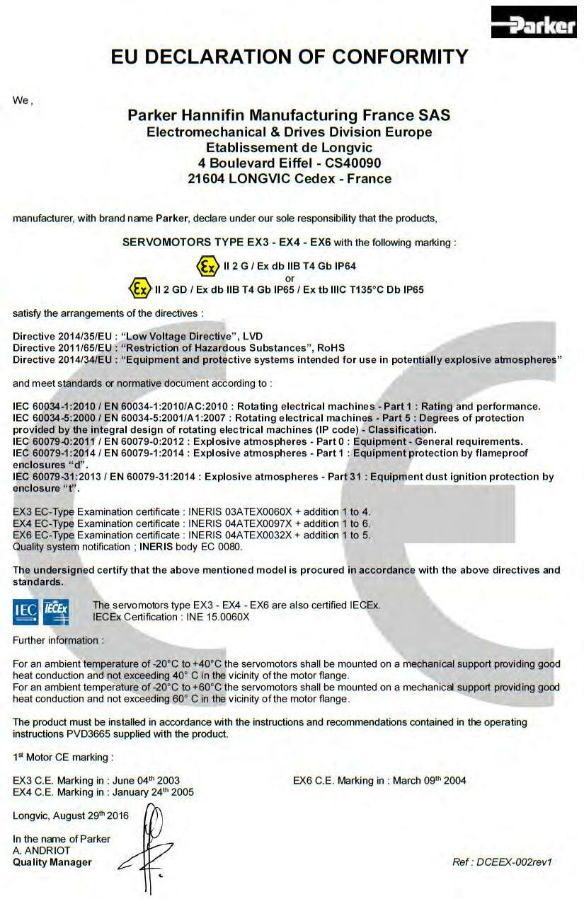
1.2.4.1. EX3-EX4-EX6 ATEX/IECEx gazeous atmospheres
Suitable for ATEX/IECEX servomotors
II 2 G Ex d IIB T4 IP64 - II Outside industries - 2 Intermittent presence of gas - d Explosionproof - II B Ethylene or propane
-
The EC certifications are marked with a X It seems the using of the motor must be in accordance with special conditions explained below:
In case of fail of a screw used to assemble the parts of the flameproof enclosure, the new part must have a quality class superior or equal to 8.8.
In case of an using in dusty explosive atmospheres, the user must perform regular cleaning operations on the motor to avoid dust deposits.
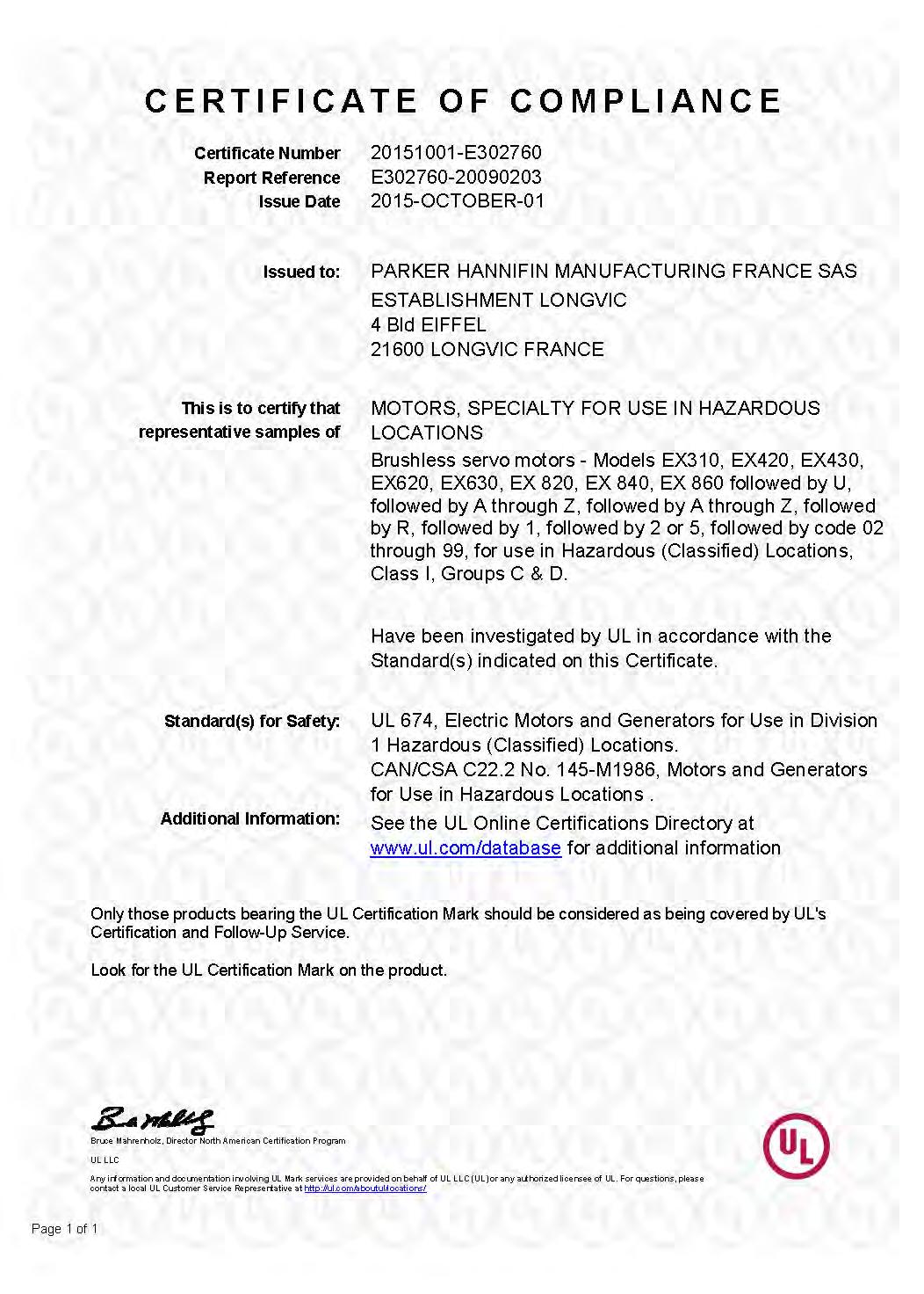
Suitable for UL servomotors
All informations and datas are avaible on : http://www.parker.com/eme/ex
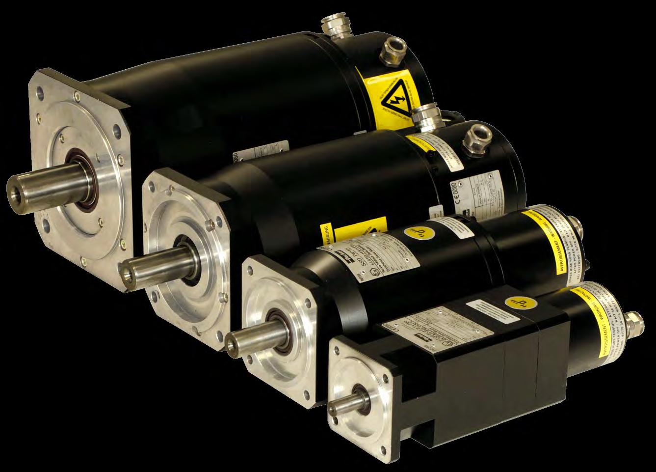
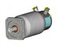
The EX servomotors from Parker are specifically designed to operate in explosive atmospheres for industrial applications.
The EX motors are brushless synchronous servomotors, with permanent magnets, based on NX active parts.
A large set of torque / speed characteristics, options and customization possibilities are available, making EX servomotors the ideal solution for most servosystems applications in explosive atmospheres
Advantages
- High precision
- High motion quality
- High dynamic performances
- Low cogging
- Compact dimensions and robustness
- Large set of options and customization possibilities
- CE, IECEx and UL marking certification available.
Painting applications
Packaging machinery
Robot applications
Special machines
Cleaning applications
Printing applications
Actuator for valve in Oil&Gas and Energy applications
Motor type
EX3, EX4, EX6
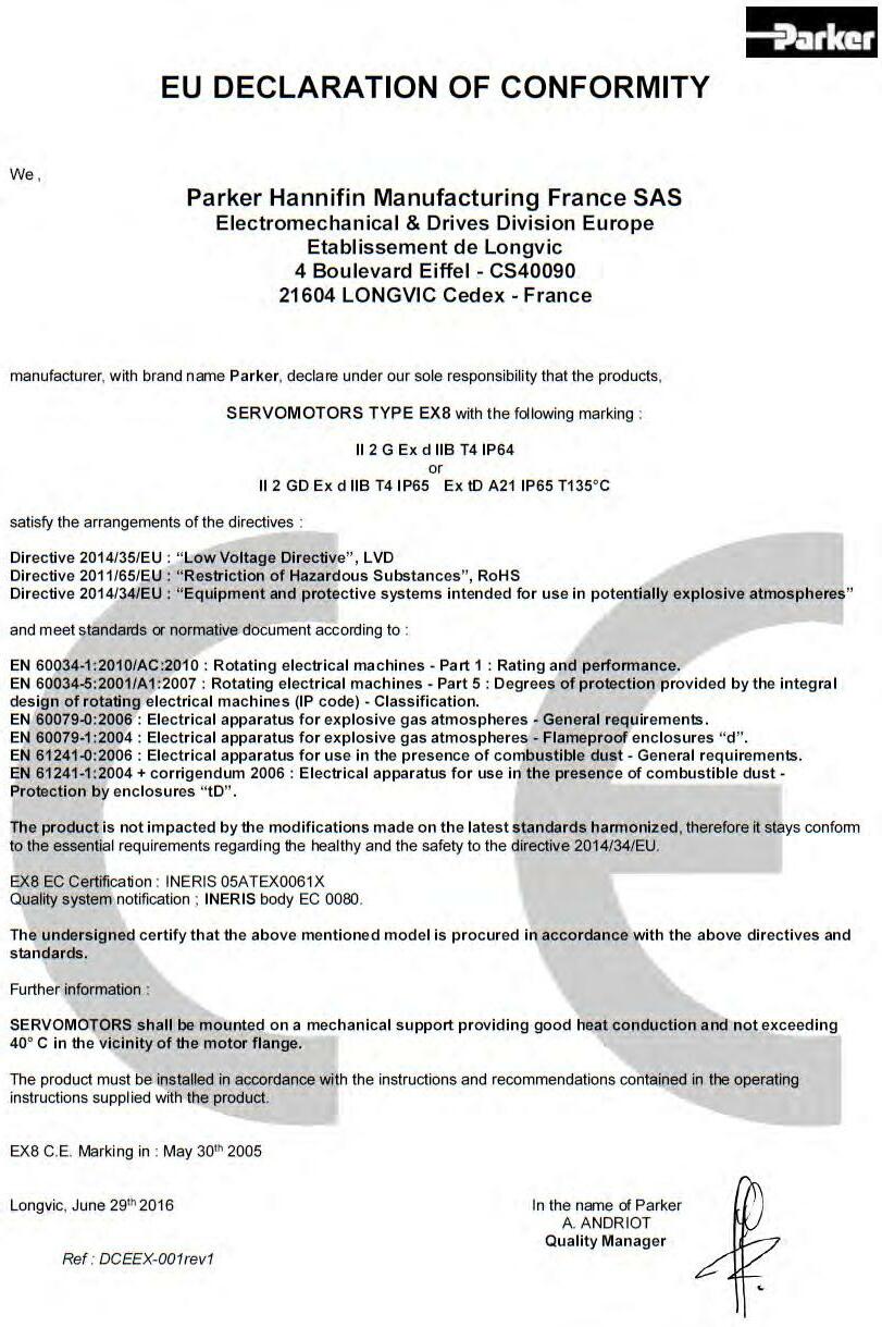
EX8
Permanent-magnet synchronous motor
Magnets material Neodymium Iron Boron
Number of poles 10
Type of construction
Degree of protection
IMB5 – IMV1 – IMV3 (EN60034-7)
Gazeous atmosphere : IP64, IP65
Combustible dust atmosphere : IP65
Cooling Natural cooling
Rated voltage 230VAC, 400 VAC
Insulation of the stator winding
Class F according to IEC 60034-1
Class F according to IEC 60034-1 with potting
Altitude Up to 1000m (IEC 60034-1)
Ambiant temperature
Storage temperature
No allowed for higher altitude
-20°C to +40°C
-20°C to +60°C with performances derating
-20°C to +60°C
Connection Electronic plate with cable glands
Marking CE and IECEx
Paint Black RAL9005
Sensor
Resolver as a standard
Sick encoder - Hiperface: SKS36 and SKM36
SRS50 and SRM50 – on request and not available for EX3
Heidenhain Endat encoder: ECN1113 and EQN1125 – on request and not available for EX3 and EX4
Sensorless
Incremental 2048 pulses and with commutation (10 poles) – on request
Brake
Thermal protection
Parking brake as an option
Thermoswitches + thermofuse
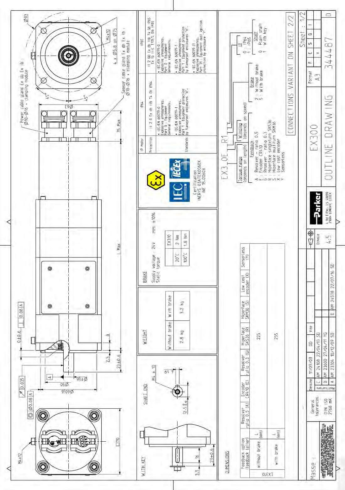
Remark Numerous customization are possible on request (special shaft, special flange,…)
Motor type
EX3, EX4, EX6 EX8
Permanent-magnet synchronous motor
Magnets material Neodymium Iron Boron
Number of poles 10
Type of construction
IMB5 – IMV1 – IMV3 (CEI 60034-7)
Degree of protection IP65
Cooling Natural cooling
Rated voltage 230VAC, 400 VAC, 480 VAC
Insulation of the stator winding Class F according to IEC 60034-1 Class F according to IEC 60034-1 with potting
Altitude Up to 1000m (IEC 60034-1)
Ambiant temperature -20°C to +40°C
Storage temperature
-20°C to +60°C
Connection Electronic plate with threaded holes
Marking UL
Paint Without
Sensor
Resolver as a standard
Sick encoder - Hiperface: SKS36 and SKM36
SRS50 and SRM50 – on request and not available for EX3
Heidenhain Endat encoder: ECN1113 and EQN1125 – on request and not available for EX3 and EX4
Sensorless
Brake Parking brake in option
Thermal protection
Thermoswitches + thermofuse
Remark Numerous customization are possible on request (special shaft, special flange,…)
The EX servomotors are defined by its electrical and mechanical characteristics, by its accompanying accessories and by any customer specificity. This information is coded and entered in the “Type” column on the manufacturer’s plate for the basic codification; the specificities are entered in a separate column.
Product Series
Motor size
1, 2, 3, 4, 6 or 8 in relation with the motor diameter
Motor length up to 60 depend on size
Motor version
E: ATEX/IECEx motor
U: UL motor
Feedback Sensor
A: resolver 2 poles transformation ratio = 0.5
K: without sensor
R: Hiperface encoder singleturn SKS36 (128pulses)
S: Hiperface encoder mutiturn SKM36 (128pulses)
T: Hiperface encoder singleturn SRS50 (1024pulses)
U: Hiperface encoder mutiturn SRM50 (1024pulses)
V: Endat encoder singleturn ECN1113– on request
W: Endat encoder multiturn ECN1125– on request
X: Incremental 2048ppr and with commutation – on request
Y: sensorless series for 650S drive
Z : Special encoder
Torque / Speed Characteristics
See motor data
Painting
R: no painting
B: Black painting
Electric connection
1: Cable gland or threaded holes (UL)
Break and thermal sensor option
2: Without brake
5: With brake
Mechanical Interface
00: IP64 plain shaft
01: IP64 key on shaft
Other: custom code
10: IP65 with plain shaft
11: IP65 with key on shaft
3.1.1.
EX motors are designed to operate in area:
with a pressure between 80 kPa (0.8 bar) and 110 kPa (1.1 bar).
air with normal oxygen content, typically 21 % v/v.
air with a maximum relative humidity of 80%, without condensation. In other conditions, please consult us.
3.1.2. Altitude
From 0 to 1000 m : no derating > 1000 m : the EX motors are not designed to operate in hazardous area for this altitude.
3.1.3.
EX servomotors are designed to operate with a maximum ambient temperature of 40°C. In case of using with an ambient temperature above 40°C and less or equal than 60°C, a derating of performances is applied according to data recommended by Parker.
The selection of the right motor can be made through the calculation of the rms torque Mrms (i.e. root mean squared torque) (sometimes called equivalent torque). This calculation does not take into account the thermal time constant. It can be used only if the overload time is much shorter than the copper thermal time constant. The rms torque Mrms reflects the heating of the motor during its duty cycle.
Let us consider:
- the period of the cycle T [s],
- the successively samples of movements i characterized each ones by the maximal torque Mi [Nm] reached during the duration ti [s]
So, the rms torque Mrms can be calculated through the following basic formula:
Example:
For a cycle of 2s at 0 Nm and 2s at 10Nm and a period of 4 s, the rms torque is
Illustration :
Acceleration-deceleration torque: 10 Nm for 0,1 s.
Resistant torque: 1 Nm during all the movement.
Max-min speed: 2800 rpm during 0,2 s.
Max torque provided by the motor: 11 Nm.
rms torque: 6 Nm.
The maximal torque Mi delivered by the motor at each segment i of movement is obtained by the algebric sum of the acceleration-deceleration torque and the resistant torque. Therefore, Mmax corresponds to the maximal value of Mi.
Selection of the motor :
The motor adapted to the duty cycle has to provide the rms torque Mrms at the rms speed(*) without extra heating. This means that the permanent torque Mn available at the average speed presents a sufficient margin regarding the rms torque Mrms
(*) rms speed is calculated thanks to the same formula as that used for the rms torque. The mean speed cannot be used (in general mean speed is equal to zero). Only use the rms speed
Furthermore, each Mi and speed associated Ωi of the duty cycle has to be located in the operational area of the torque vs speed curve.
Selection of drive depends on its rated power, rated current and its mode selection which leads to the maximal current duration.
Please refer to the drive technical documentation for any further information and to select the best motor and drive association.
AC890 PARKER drive example:
The rated current provided by the AC890 drive depends on its rated power and its mode selection. “Vector mode” is used for induction motors while “Servo mode” is used for brushless AC motors. With EX motors the power is usually < 37 kW, the rated current corresponds to 100 %.
Example n°1 : The application needs:
- a rms torque of 7 Nm at the rms speed of 2000 rpm,
- an acceleration torque of 10 Nm,
- a maximal speed of 2800 rpm.
Selection of the motor:
The selected motor is the type EX620EAO. The nominal speed is equals to 4300 rpm. The maximal speed is equals to 4300 rpm. The torque sensitivity is equals to 1.27 Nm/Arms.
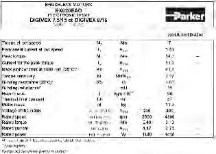
The permanent current I0 of the motor is 5.51 Arms for M0=7 Nm at low speed. The nominal current In of the motor is 2.46 Arms for Mn = 3.13 Nm at the nominal speed.
Selection of the drive:
The drive has to provide at least a permanent current equals to I0 (5.51 Arms). In order to obtain an acceleration torque of 10 Nm, the current will be about 8 Arms. This means that the drive has to provide at least 8 Arms as transient current.
Therefore, we can select the drive AC890SD-53 2100 B which delivers under 400 VAC: 6 Arms as permanent current and
6*200%=12 Arms as maximal transient current during 4 s. The drive is set with “Servo Mode”.
Example n°2 :
This times; the application needs :
- a permanent torque of 5 Nm at low speed,
- a rms torque of 5 Nm at the rms speed of 1890 rpm,
- an acceleration torque of 7.6 Nm,
- a maximal speed of 2800 rpm.
Selection of the motor:
The selected motor is the type EX620EAO. The nominal speed is equals to 4300 rpm. The maximal speed is equals to 4300 rpm. The torque sensitivity is equals to 1.27 Nm/Arms.
Selection of the drive:
The drive has to provide a permanent current equals to 4 Arms to obtain 5 Nm. In order to obtain an acceleration torque of 7.6 Nm, the current will be of about 6 Arms This means that the drive has to provide at less 6 Arms as transient current.
Compared to the previous example n°1, it is now possible to decrease the size of drive.
Therefore, we can select the drive AC890SD-53 1600 B which delivers under 400 VAC:
4 Arms as permanent current and
4*200%=8 Arms as maximal transient current during 4 s. The drive is set with “Servo Mode”
Recommended reduced current at speed < 3 rpm:
Warning: The current must be limited to the prescribed values. If the nominal torque has to be maintained at stop or low speed (< 3 rpm), imperatively limit the current to 70% of I0 (permanent current at low speed), in order to avoid an excessive overheating of the motor.
Please refer to the drive technical documentation for any further information and to choose functions to program the drive.
It is possible to use the EX motor with a current higher than the permanent current. But, to avoid any overheating, the following rules must be respected.
1) The peak currents and peak torques given in the data sheet must never be exceeded
2) The thermal equivalent torque must be respected (§3.1.3)
3) If 1) and 2) are respected (it can limit the peak current value or duration), the peak current duration (tp) must be limited, in addition, accordingly to the following table (Io is the permanent current at low speed):
The peak current duration is calculated for a temperature rise of 3°C Consult us for more demanding applications.
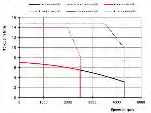
The torque vs speed graph below explains different intrinsic values of the next tables.

Torque
Peak Torque
Permanent
Low Speed
Torque
Rated torque
Stall torque
3 rpm
Rated Power
Rated Max Speed speed speed
UL 400V
Caution: The efficiency curves are typical values They may vary from one motor to an other
Caution: The efficiency curves are given for an optimal motor control (no voltage saturation and optimal phase between current and EMF)
Caution: The efficiency curves do not include the losses due to the switching frequency.
Caution: Following data result from our best estimations but are indicative They can vary from one motor to another and with temperature. No responsibility will be accepted for direct or indirect losses or damages due to the use of these data.
(Following data are indicative, without lip seal, IP64 motor)
Torque losses (N.m) = Tf + Kd x speed(rpm)/1000
3.2.8. Time constants of the motor
3.2.8.1. Electric time constant:
With following values given in the motor data sheet
Lph_ph inductance of the motor phase to phase [H],
Rph_ph resistance of the motor phase to phase at 25°C [Ohm].
Example:
Motor series EX620EAO
Lph_ph = 14 mH or 14.10-3 H
Rph_ph at 25°C = 1.63 Ohm
elec = 14.10-3/1.63 = 8.6 ms
An overall summary of motor time constants is given a little further
3.2.8.2. Mechanical time constant:
With following values obtained from the motor data sheet:
Rph_ph resistance of the motor phase to phase at 25°C [Ohm],
J inertia of the rotor [kgm²],
Keph_ph back emf coefficient phase to phase [Vrms/rad/s].
The coefficient Keph_ph in the formula above is given in [Vrms/rad/s]
To calculate this coefficient from the datasheet, use the following relation:
Example:
Motor series EX620EAO
Rph_ph at 25°C = 1.63 Ohm
J = 98.10-5 kgm²
Keph_ph [Vrms/1000rpm] = 81.7 [Vrms/1000rpm]
Keph_ph [Vrms/rad/s] = 81.7/(2**1000/60) = 0.7802 [Vrms/rad/s]
mech=0.5*1.63*98.10-5 /(0.7802²) = 1.3 ms
Remarks:
For a DC motor, the mechanical time constant mech represents the duration needed to reach 63% of the final speed when applying a voltage step without any resistant torque. However this value makes sense only if the electric time constant elec is much smaller than the mechanical time constant mech (for the motor EX620EAO taken as illustration, it is not the case because we obtain mech<elec.).
An overall summary of motor time constants is given a little further.
3.2.8.3. Thermal time constant of the copper:
With:
Rth thermal resistance between copper and ambient temperature [°K/W]
Cthcopper thermal capacity of the copper [J/°K] Masscopper mass of the copper (winding) [kg]
Hereunder is given an overall summary of motor time constants:
The typical speed ripple for a EX motor with a resolver at 4000rpm is 3% peak to peak. This value is given as indicative data because depending on the settings of the drive (gains of both speed and current regulation loops, presence of filtering or not, load inertia, resistant torque and type of sensor in use), without external load (neither external inertia nor resistant torque).
The typical cogging for a EX series below is the maximum value peak to peak in N.cm:
The nominal characteristics and especially the rated speed, maximal speed, rated power, rated torque, depend on the nominal voltage supplying the motor considered as the rated voltage. The rated data mentioned in the data sheet are given for each association of motor and drive. Therefore, if the supply voltage changes, the rated values will also change. As long as the variation of the rated voltage remains limited, for instance to 10% of the nominal value, it is possible to correctly evaluate the new rated values as illustrated below.
Example: Extract of Ex630EAI datasheet

If we suppose that the rated voltage Un=400 Vrms decreases of 10% ; this means that the new rated voltage becomes Un2=360 Vrms
Rated speed:
The former rated speed Nn=3000 rpm obtained with a rated voltage Un=400 Vrms and an efficiency =92% leads to the new rated speed Nn2 given as follows:
Maximum speed:
The former maximum speed Nmax = 3000 rpm obtained with Un =400 Vrms and a speed Nn =3000 rpm leads to the new maximum speed Nmax2 given as follows:
N.B.
If the rated voltage increases (Un2 > Un), the new rated speed Nn2 and the new maximum speed Nmax2 will be greater than the former ones Nn and Nmax. Moreover you will have to check that the drive still shows able to deal with the new maximum electric frequency.
Warning: If the main supply decreases, you must reduce the maximum speed accordingly in order to do not damage the motor. In case of doubt, consult us.
Rated power:
The former rated power Pn=2270 W obtained with Un=400 Vrms leads to the new rated power Pn2 given as follows:
Rated torque: The former rated torque Mn = 7.24 Nm obtained with Un =400 Vrms leads to the new rated torque Mn2 given as follows:
The motors fed by converters are subject to higher stresses than in case of sinusoidal power supply. The combination of fast switching inverters with cables will cause overvoltage due to the transmission line effects. The peak voltage is determined by the voltage supply, the length of the cables and the voltage rise time. As an example, with a rise time of 200 ns and a 30 m (100 ft) cable, the voltage at the motor terminals is twice the inverter voltage. The insulation system of the servomotors EX is designed to withstand high repetitive pulse voltages and largely exceeds the recommendations of the IEC/TS 60034-25 ed 2.0 200703-12 for motors without filters up to 500V AC (See figure 1).
Curve
Figure 1: Minimum Voltage withstands characteristics for motors insulations according to IEC standards. At the top are the typical capabilities for the EX motors.
Note: The pulse rise times are defined in accordance with the IEC/TS 60034-17 ed4.0 200605-09.
The EX motors can be used with a supply voltage up to 480 V under the following conditions:
The pulse rise times must be longer than 50 ns.
The repetitive pulse voltages must not exceed the values given in figure 1, “Curve EX motors” in dark blue.

The EX motors carry ATEX and UL certification and due to this certificate, they are subjected to strict rules regarding their use. One of such rules is the us of a servoamplifier that meets specific characteristics.
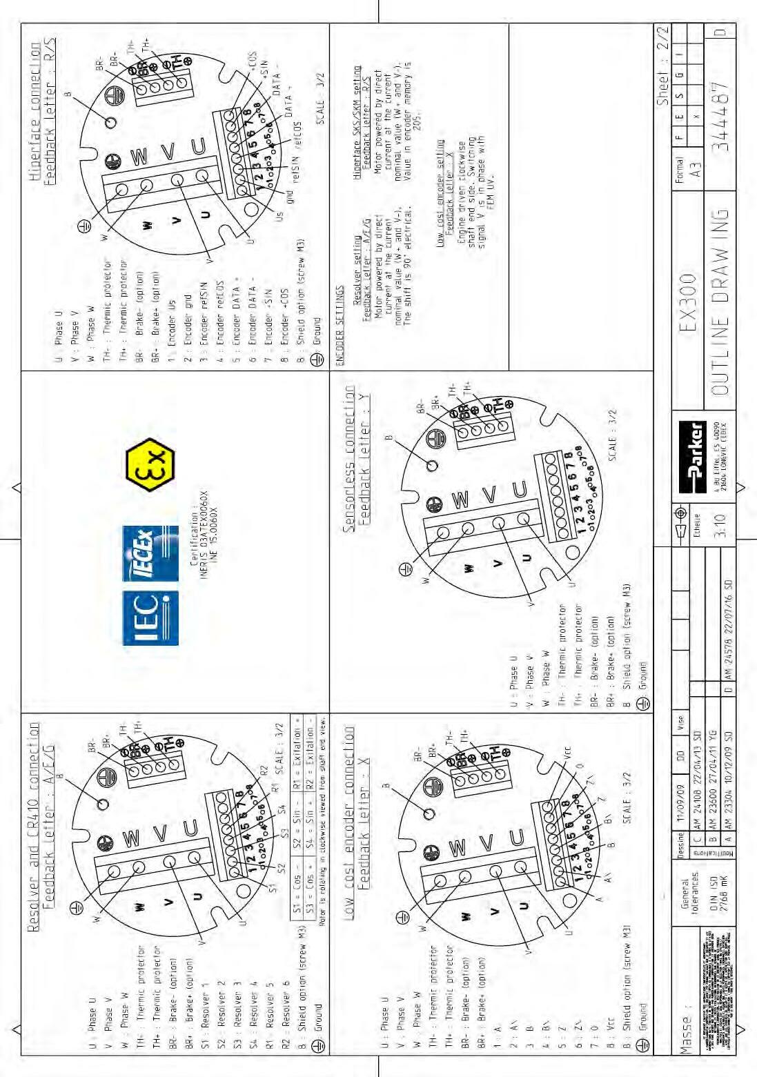
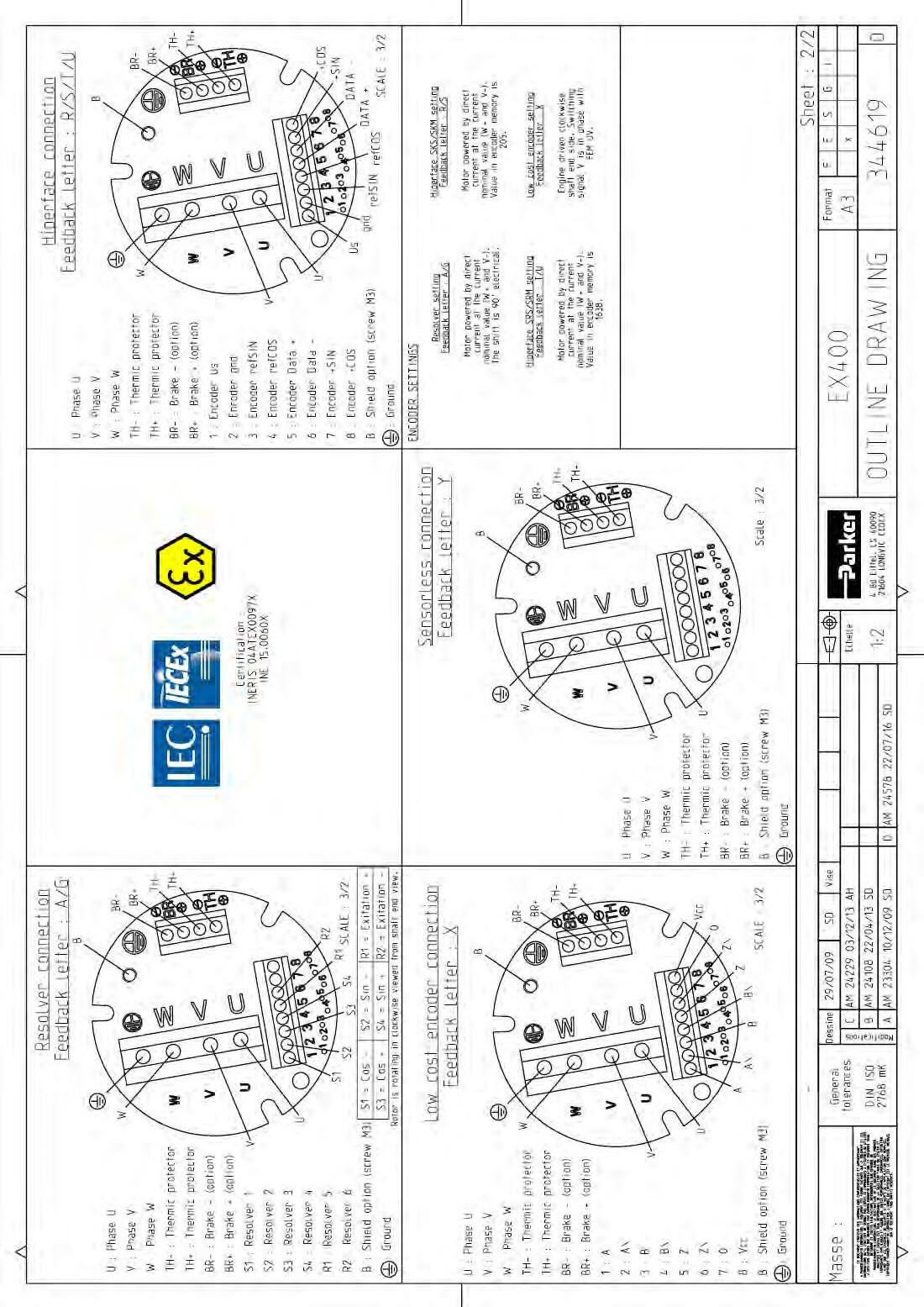
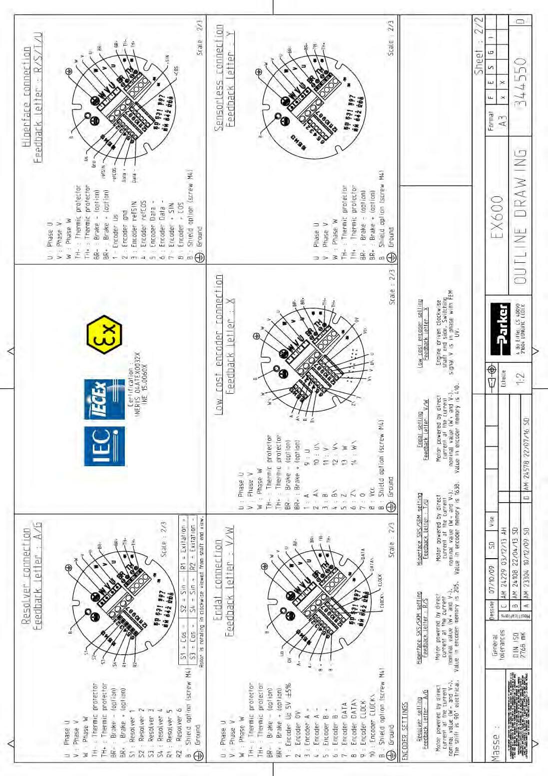
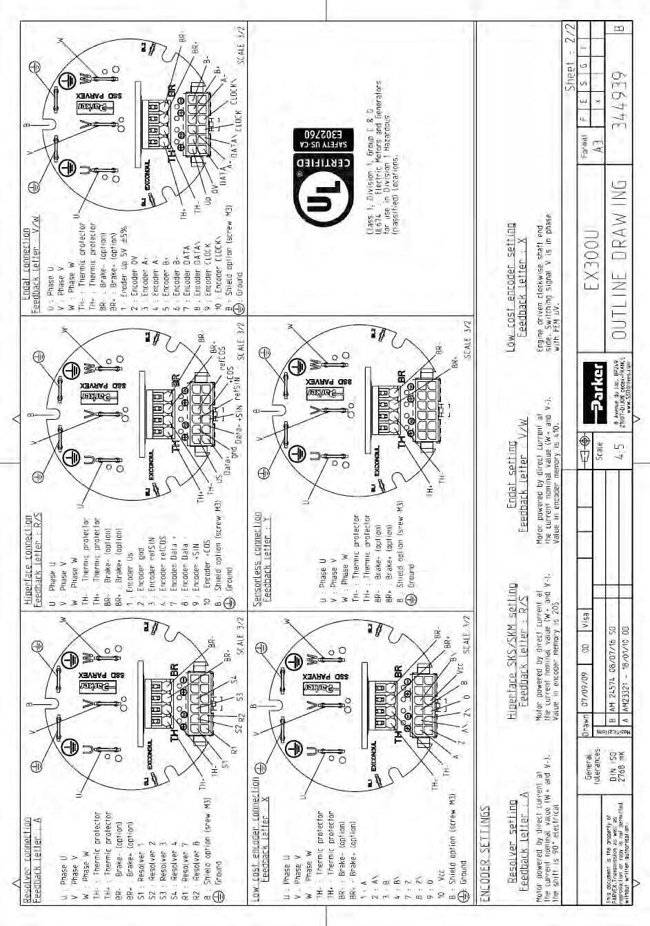
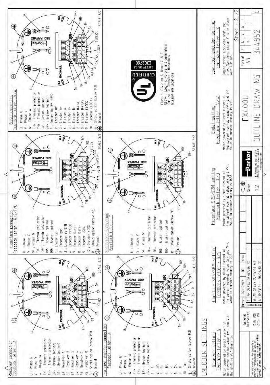
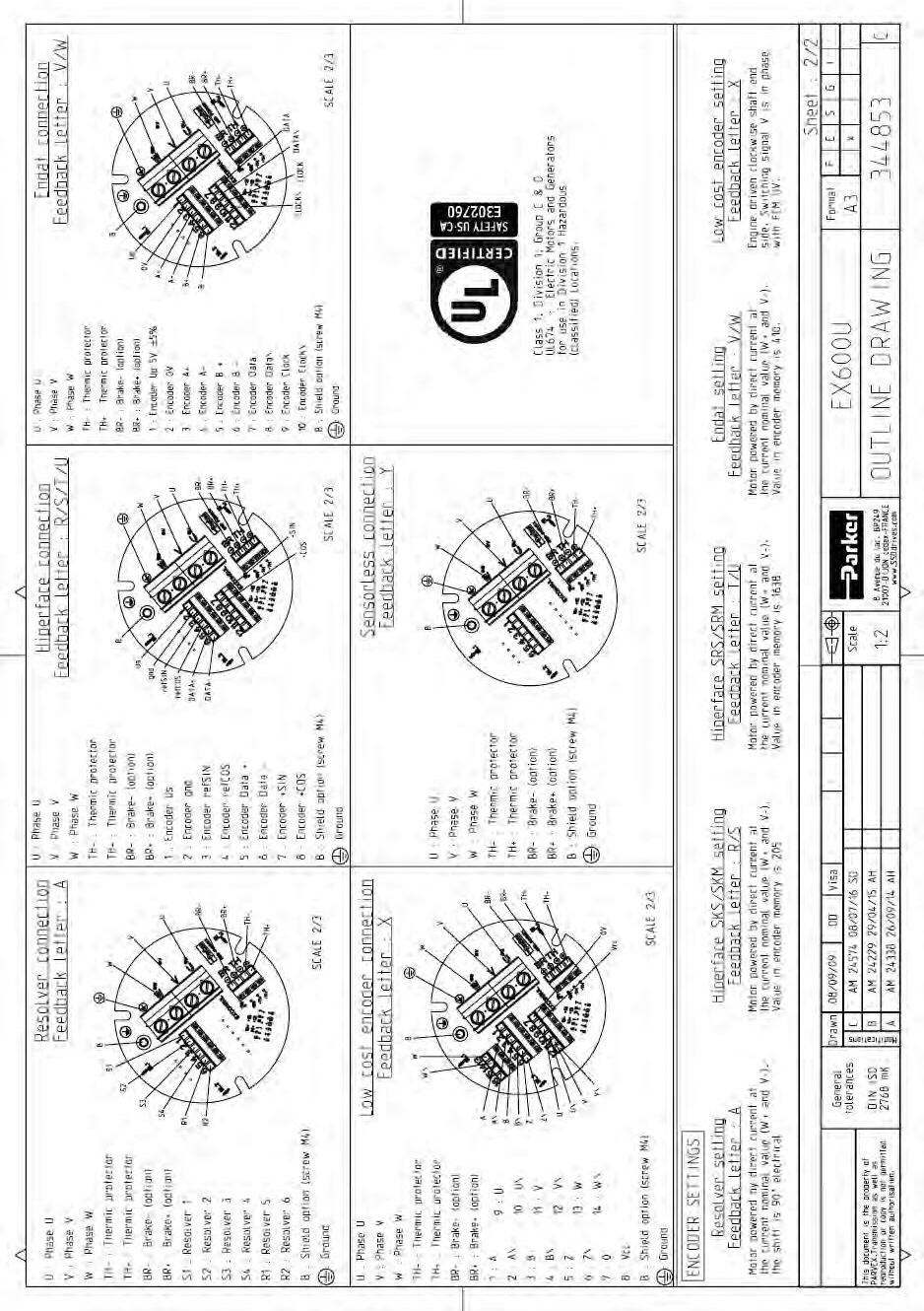
Warning : EX motors must be connected in accordance with the diagrams given in chapter §4.3.3

Keep in mind that EX motors are equipments with protect mode “db” flameproof enclosure for hazardous area of gas and with protection by enclosure "tb" for hazardous area of dust ignition.
When installing electris system in hazardous locations, carefully observe the corresponding country regulations.
Warning : The user has the entire responsibility to design and prepare the support, the coupling device, shaft line alignment, and shaft line balancing.
Foundation must be even, sufficiently rigid and shall be dimensioned in order to avoid vibrations due to resonances. The servomotors need a rigid support, machined and of good quality. The maximum flatness of the support has to be lower than 0.05mm.
The motor vibration magnitudes in rms value are in accordance with IEC 60034-14 grade A: maximum rms vibration velocity for EX is 1.3mm/s for rigid mounting
Warning : A grade A motor (according to IEC 60034-14) well-balanced, may exhibit large vibrations when installed in-situ arising from various causes, such as unsuitable foundations, reaction of the driven motor, current ripple from the power supply, etc.
Vibration may also be caused by driving elements with a natural oscillation frequency very close to the excitation due to the small residual unbalance of the rotating masses of the motor. In such cases, checks should be carried out not only on the machine, but also on each element of the installation. (See ISO 10816-3).
Warning : A bad setting of the electronic control of the close loop (gain too high, incorrect filtring …) can occur an instability of the shaft line, vibration or/and breakdown - . Please consult us


Frequency domain :10 to 55 Hz according to EN 60068 -2-6
Vibration resistance to the shaft end :
- radial 3 g
- axial 1 g
3.5.2. Maximum load acceptable on the shaft
Warning : The values written in the table are given for a load placed on the middle of the shaft like the picture below.
Warning :
Due to the small ATEX airgap requirements between the shaft and the front flange, the radial loads on the shaft are lower than standard NX motors.

The ATEX airgap requirements depend on the volume of the motor and can lead to lower radial loads for bigger motors.
Warning :
Regarding to these shaft loads, you must’nt use a pulley belt system without a load take-up system.
In compliance with the IEC 60034-1 standards: The ambient air temperature shall not be less than -20°C and more than 40°C.
It is possible to use the motors in an higher ambient temperature between 40°C to 60°C but with an associated derating to the motor performances.
Warning: To reach the motor performances calculated, the motor must be thermally well connected to a aluminium flange with a dimension of 400 mm x 400 mm and with a thickness of 12 mm.
Caution: the ambient air temperature shall not exceed 40°C (respectively 60°C with associated derating) in the vicinity of the motor flange
Warning: A significant part of the heat produced by the motor is evacuated through the flange.
if the air is not able to circulate freely around the motor,
if the motor is mounted on a surface that dissipates not well the heating (surface with little dimensions for instance),
if the motor is thermally isolated,
if the motor is mounted on a warm surface (mounted on a gearbox for instance),
then the motor has to be used at a torque less than the rated torque.
The drive guarantees a 1st level of safety but it is not sufficient. Safety is guaranteed by the independent relay system described in the connection diagram (§4.3.3) which constitutes an independent protection circuit meeting safety classification SIL2 in accordance with the standard IEC 61508.
In the motor, there are two kinds of thermal sensors used for the safety. Both devices are wired in-series with the coil of the drive power contactor.
Two thermoswitches fitted in the servomotor coil mean that the circuit is mechanically opened on a basis at 125°C±5°C. This protection is reversible, after a decreasing of the temperature under the basis, the circuit is mechanically closed.
A thermofuse fitted with a contact on the servomotor frame means that the circuit is mechanically opened on a permanent basis at 130°C-5°C. In case of an over temperature and thermoswitches default, the thermo fuse cuts off permanently the power supply to the contactor coil. Both thermoswitches and thermofuse are wired in-series with the coil of the drive power contactor. If the maximum temperature is reached, the thermoswitches are opened and temporarily cut off the power supply to the contactor coil. If the temperature reaches a dangerous level (thermoswitches default), the thermofuse melts; permanently cutting off the power supply to the contactor coil.
The drive can be equipped with a Safe Torque Off function in accordance with EN ISO13849-1 : 2006 and EN 61800-5-2:2006 and validated by a notified organization. In this case the safety system can be connected to this function with a validation of a notified organization.
Caution : (see diagrams §4.3.3) :
Make sure the parameters of the contactor and the connecting are strictly followed.
The motor is out of order if the thermofuse is activated!
The power contactor KM1 should be replaced in accordance with its operation lifespan and number of manoeuvres. A yearly test, intended to check on the ability of the contactor to detect condition changes, should also be carried out.
The thermal sensors, due to their thermal inertia, are unable to follow very fast winding temperature variations. They acheive their thermal steady state after a few minutes.
Warning: To protect correctly the motor against very fast overload, please refer to 3.1.6. Peak current limitations

3.8.1. Inlet cables for ATEX/IECEx version.
The servomotors EX have two cable glands with metric thread :one for the feedback cable and the other for the power. These cable glands are place in axial or radial position on the feedback cover depending the motor option.
The informations of these cable glands are placed in the §4.4.
The cable gland expected for the feedback cable could be replace by an ATEX thread cap in case of a servomotor in sensorless.
It is forbidden to change a cable gland without the Parker agreement.
3.8.2. Wires sizes
In every country, you must respect all the local electrical installation regulations and standards
Not limiting example in France: NFC 15-100 or IEC 60364 as well in Europe
Cable selection depends on the cable construction, so refer to the cable technical documentation to choose wire sizes
Some drives have cable limitations or recommendations; please refer to the drive technical documentation for any further information.
Cable selection
At standstill, the current must be limited at 80% of the low speed current Io and cable has to support peak current for a long period. So, if the motor works at standstill, the current to select wire size is
2 x 0.8 Io 1,13 x Io.
For the ATEX installations in ambient temperature of 40°C or 60°C, you have to use special cables C2 type auto-extinguish regarding the standard EN 50265-2-1.
Warning : the cables used in the :
EX3 can reach a temperature of 80°C,
EX4 can reach a temperature of 91°C,
EX6 can reach a temperature of 95°C,
EX8 can reach a temperature of 95°C
Warning : for a safe use, the EX3 servomotors has to be used with cable which withstand a maximum temperature of 80°C.
Warning : for a safe use, the EX4/EX6/EX8 servomotors has to be used with cable which withstand a maximum temperature of 100°C.
It is mandatoryto connect 2 (green-yellow) ground cables between the motor frame and machine.
the first one is connected to ground screw on the PCB inside the motor,
the other one is connected to the external motor housing The connecting of these two grounding devices is mandatory in order to comply with ATEX standard IEC/EN 60079-0.
The ground cable cross-section must be the same as the power cable crosssection
For motors windings which present low inductance values or low resistance values, the own cable inductance, respectively own resistance, in case of large cable length can greatly reduce the maximum speed of the motor. Please contact PARKER for further information.
Caution: It might be necessary to fit a filter at the servo-drive output if the length of the cable exceeds 25 m. Consult us.
The length of the cable must be of 3 meters min.
3.8.5.
3.8.5.1.

3.8.6. ATEX/IECEx motor conenction
3.8.6.1. Connection of the power and the feedback cables with terminals
Step 1 – Remove the rear cover :
1. Unscrew the 4 nuts Ref 1.
2. Unscrew the cable gland caps Ref 2.
3. Remove the cover Ref 3.
Step 2 – Connection of the feedback cable :
1. Insert the cable in the cable gland Ref 2.
2. Strip the wires on 3 mm.
3. Put the wires in the terminals on the PCB Ref 4 and tighten each screws at the torque value of 0,6 N.m.
4. Make the shielding connection with the connection of the terminal on the screw Ref 5 at the torque value of : Motor size Torque (N.m) EX3-EX4 M3 screw 1,7


M4 screw 2,5
5. If the shielding connection is not necessary, cut the wire short the cable.
Step 3 – Connection of the power cable :
1. Insert the cable in the cable gland Ref 2.
2. Strip the wires on 3 mm.
3. Put the wires U, V, W, Ground, TH+ and TH- and also BR+ and BR- in a case of a motor with a brake in the terminal of the PCB Ref 4 and tighten each screws at the torque value of 0,6N.m.
4. Make the shielding connection with the connection of the terminal on the screw Ref 5 at the torque value of :
5. If the shielding connection is not necessary, cut the wire short the cable
Step 4 – Fitting of the rear cover :
1. Slowly take up any slack in the cables and close the cover Ref 3.
2. Tighten the cable gland caps Ref 2 at the torque value of :
3. Tighten the screws of the connection modules Ref 6 at the torque value of 0,5 N.m.
4. Place the rear cover Ref 3 and take care to don’t hurt the toric seal placed on the rear flange
5. Tighten the 4 nuts Ref 1 at the torque value of :
6. Connect the outside ground with the screw Ref 7 and tighten it at the torque value of :
3.8.6.2. Connection of the feedback and power cable with connector on EX3 :
Step 1 – Remove the rear cover :
1. Unscrew the 4 nuts Ref 1.
2. Unscrew the cable gland caps Ref 2.
3. Remove the cover Ref 3.
Step 2 – Connection of the feedback cable :
1. Insert the cable in the cable gland Ref 2.
2. Strip the wires on 3 mm and crimp them in the connector.
3. Plug the connector in the terminal of the PCB Ref 4 .

4. Crimp the shielding wire in the connector and plug the connector in the terminal Ref 5.
5. If the shielding connection is not necessary, cut the wire short the cable.
Step 3 – Connection of the power cable :
1. Insert the cable in the cable gland Ref 2.
2. Strip the wires on 3 mm and crimp them in the connector
3. Put the wires U, V, W, Ground, TH+ and TH- and also BR+ and BR- in a case of a motor with a brake equiped with their connectors on the terminal of the PCB Ref 4.

4. Crimp the shielding wire in the connector and place the connector in the terminal Ref 5.
5. If the shielding connection is not necessary, cut the wire short the cable
1. Slowly take up any slack in the cables and close the cover Ref 3.
2. Tighten the cable gland caps Ref 2 at the torque value of :
Cable gland size Torque (N.m) M16 12,5 M20 20
3. Tighten the screws of the connection modules Ref 6 at the torque value of 0,5 N.m.
4. Place the rear cover Ref 3 and take care to don’t cut the toric seal placed on the rear flange.
5. Tighten the 4 nuts Ref 1 at the torque value of 5,6 N.m.
6. Connect the outside ground with the screw Ref 7 and tighten it at the torque value of 2,5 N.m.
3.8.7. EX3-EX4 UL connection
3.8.7.1. Connection of the feedack and power cable with connector:
Step 1 – Remove the rear cover:
1. Unscrew the 4 nuts Ref 1.
2. Unscrew the cable gland caps Ref 2.
3. Remove the cover Ref 3.
Step 2 – Connection of the feedback cable :
1. Insert the cable in the cable gland or conduit stop Ref 2.

2. Strip the wires on 3 mm and crimp them on the contacts supplied in the terminal part kit with the manual crimp tooling Molex N°0638190000 for wire diameter AWG 20-24.
3. Place the contacts in the connector Ref 8.


4. Place the connector inside the PCB connector Ref 4.
5. Crimp the shielding wire in the connector and plug the connector in the terminal Ref 5.
6. If the shielding connection is not necessary, cut the wire short the cable
Step 3 – Connection of the power cable :
1. Insert the cable in the cable gland or conduit stop Ref 2.
2. Strip the wires on 5mm and crimp the wires U, V, W and Ground in the faston terminals 6,8x0,8.
3. Place the wire U, V, W and Ground on the terminals and plug the wires TH+ and TH- and also BR+ and BR- in a case of a motor with a brake equiped in the terminal of the PCB Ref 4 .
4. Crimp the shielding wire in the faston terminal 2,8x0,8 and plug it on the terminal Ref 5.
5. If the shielding connection is not necessary, cut the wire short the cable
1. Slowly take up any slack in the cables and close the cover Ref 3.
2. Tighten the cable gland caps or conduits stop Ref 2.
3. Tighten the screws of the connection modules Ref 6 at the torque value of 0,5 N.m.
7. Place the rear cover Ref 3 and take care to don’t hurt the toric seal placed on the rear flange.
4. Tighten the 4 nuts Ref 1 at the torque value of 5,6 N.m.
5. Connect the outside ground with the screw Ref 7 and tighten it at the torque value of:
3.8.8. EX6-EX8 UL connection


3.8.8.1. Connection of the feedack and power cable with terminal:
Step 1 – Remove the rear cover :
1. Unscrew the 4 nuts Ref 1.
2. Unscrew the cable gland caps Ref 2.
3. Remove the cover Ref 3.
Step 2 – Connection of the feedback cable :
1. Insert the cable in the cable gland Ref 2.

2. Strip the wires on 3 mm.
3. Put the wires in the terminals on the PCB Ref 4 and tighten each screws at the torque value of 0,6 N.m.
4. Make the shielding connection with the connection of the terminal on the screw M4 Ref 5 at the torque value of 2,5 N.m.
5. If the shielding connection is not necessary, cut the wire short the cable.
Step 3 – Connection of the power cable :
1. Insert the cable in the cable gland Ref 2.
2. Strip the wires on 3 mm
3. Put the wires U, V, W, Ground, TH+ and TH- and also BR+ and BR- in a case of a motor with a brake in the terminal of the PCB Ref 4 and tighten each screws at the torque value of 0,6N.m.
4. Make the shielding connection with the connection of the terminal on the screw ref 5 at the torque value of 2,5 N.m.
5. If the shielding connection is not necessary, cut the wire short the cable.
7. Slowly take up any slack in the cables and close the cover Ref 3.
8. Tighten the cable gland caps or conduits stop Ref 2.
9. Place the rear cover Ref 3 and take care to don’t hurt the toric seal placed on the rear flange
10.Tighten the 4 nuts Ref 1 at the torque value of :
11. Connect the outside ground with the screw Ref 7 and tighent it at the torque value of :
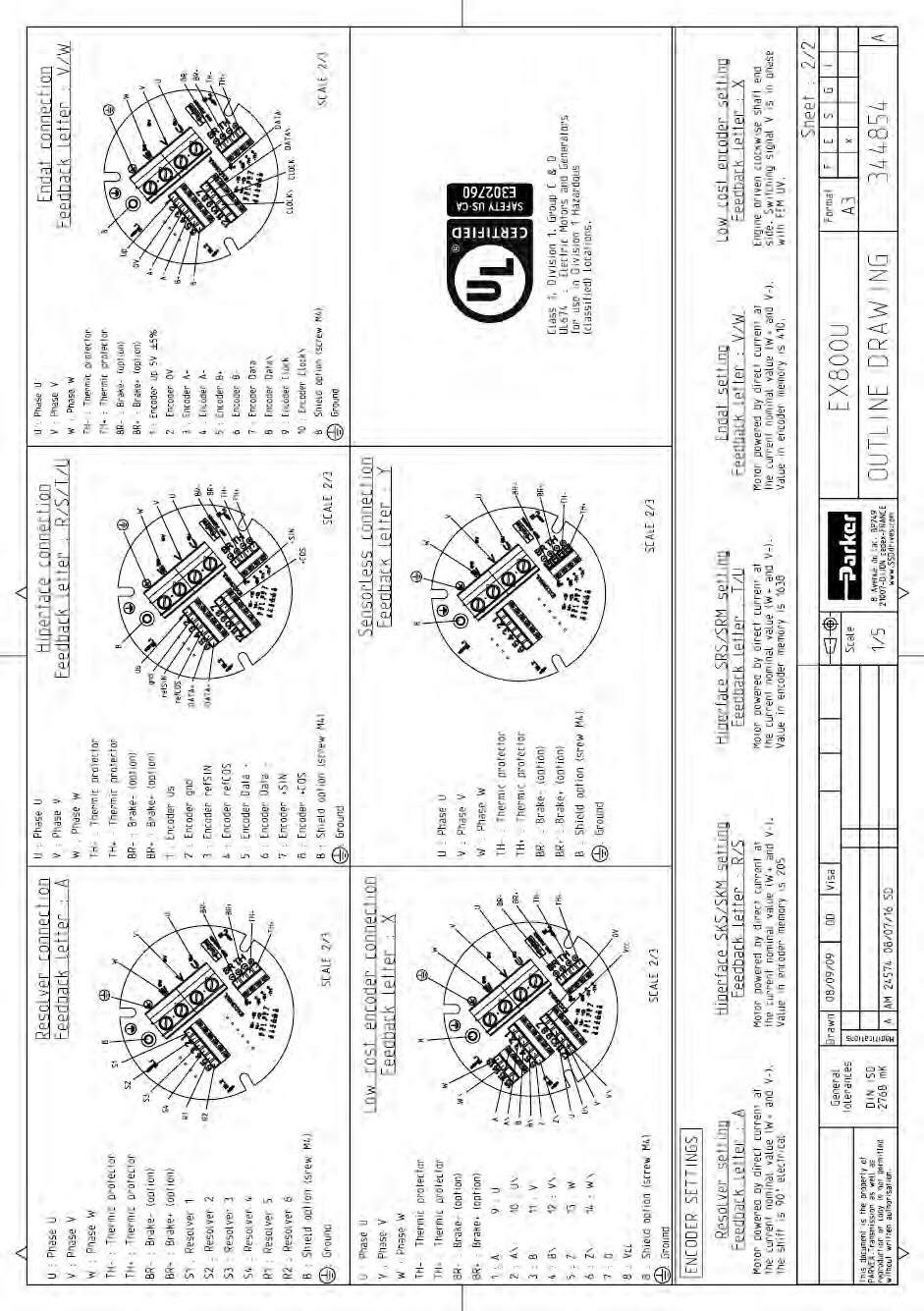
3.9.1. Shaft rotation regarding the connection. With the connection explained in the documentation and with a positive speed request on the drive, the shaft will turn in clockwise direction (see customer shaft end).
3.9.2. Resolver 2 poles transformation ratio = 0.5 – code A
Output
(primary in short circuit whatever the position of the
Dielectric
3.9.3. Sensorless – code K or Y.
The servomotors EX in sensorless version do not have a feedback cable. The connection of the power cable has to be made regading the connection diagrams in this documentation. In these detailed diagrams §4.3.3, do not take care the connection of the feedback cable and keep the same connections for the other devices
EX3, EX4, EX6 & EX8
SKS36 (Sick)
single turn encoder
Integral non-linearity ± 80’’(Error limits for evaluating sine/cosine period)
Differential non-linearity ± 40’’ (Non-linearity within a sine/cosine period)
EX3, EX4, EX6 & EX8
SKM36 (Sick)
Absolute multi turn encoder
Integral non-linearity ± 80’’(Error limits for evaluating sine/cosine period)
Differential non-linearity ± 40’’ (Non-linearity within a sine/cosine period)
3.9.6.
SRS50 (1024pulses) – code T EX4, EX6 & EX8
3.9.7.
SRM50 (1024pulses) – code U
EX6 & EX8
3.9.8.
encoder singleturn ECN1113 – code V
EX3 & EX4 ATEX EX3 UL, EX4 UL, EX6 & EX8
1113 (Heidenhain) Type Absolute single turn encoder
3.9.9.
encoder multiturn ECN1125 – code W
EX3 & EX4 ATEX EX3 UL, EX4 UL, EX6 & EX8
With unregulated power supply (AC890 PARKER drive for instance), the max cable length is 65m with 0.25mm² power supply wire due to the voltage drop into the cable itself.
Maximum Endat cable length
Please refer to the following curve to calculate the max cable length depending on the clock frequency


3.9.10. Incremental encoder - Commuted lines 10 poles – 2048pulses –code X (On request)
EX3, EX4, EX6 & EX8
Model F10 (Hengstler)
Type Incremental encoder with 10 pole commutation signals
Parker part number 220167P0003
Line count 2048 pulses per revolution
Electrical interface Line driver 26LS31
System accuracy
Incremental signals ± 2.5' commutation signals ± 6'
You can connect EX motors to PARKER servo drives : AC30, AC890, COMPAX3, PSD or SLVD.
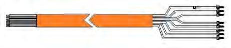
You can use complete cable with part number on the tabs below. The "xxx" in the part number must be replaced by the length in meter with a minimal length of 3m Ex : for 20m cable, "xxx" = 020.
Special requirements for ATEX servomotors
For the ATEX installations in ambient temperature of 40°C or 60°C, you have to use special cables C2 type auto-extinguish regarding the standard EN 50265-2-1
Warning : the cables used in the :
EX3 can reach a temperature of 80°C,
EX4 can reach a temperature of 91°C,
EX6 can reach a temperature of 95°C,
EX8 can reach a temperature of 95°C
Warning : for a safe use, the EX3 servomotors has to be used with cable which withstand a maximum temperature of 80°C.
Warning : for a safe use, the EX4/EX6/EX8 servomotors has to be used with cable which withstand a maximum temperature of 100°C.
The servomotors EX are available on demand with cables withstanding a temperature of 80°C on the outside surface. With this option the EX servomotors must be placed in an area with controlled temperature following the informations written in the tables just below. An over temperature must cut off the power of the motor.
Size EX4 :
Ambient temperature for a Parker standard cable using (Max 100°C)
Ambient temperature for an using of cables withstanding a max temperature of 80°C.
Size EX6 :
Ambient temperature for Parker standard cable using (Max 100°C)
Ambient temperature for an using of cables withstanding a max temperature of 80°C.
Size EX8 :
Ambient temperature for Parker standard cable using (Max 100°C)
Ambient temperature for an using of cables withstanding a max temperature of 80°C.
EX4 certified for an ambient temperature of -20 to +60°C
-20 to +60°C
-20 to +49°C
EX6 certified for an ambient temperature of -20 to +40°C
to +40°C
EX8 certified for an ambient temperature of20 to +40°C
-20 to +40°C
-20 to +25°C
EX6 certified for an ambient temperature of -20 to +60°C
to +60°C
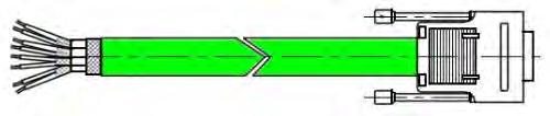
Cable reference : CS4UA1D1R0xxx
Feedback cable 6537P0059
Male 15 pins SUB-D connector reference AC 80552
SUB-D cover reference 220029P0043
Pins reference 220029P0021
Cable arrangement :
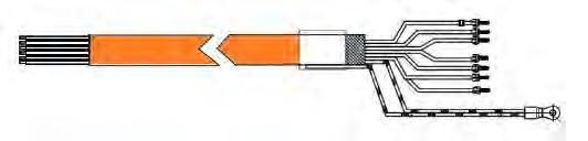
Cable reference :
CS4UV1D1R0xxx
Feedback cable 6537P0059

Male 15 pins SUB-D connector reference AC 80552
SUB-D cover reference 220029P0043
Pins reference 220029P0021
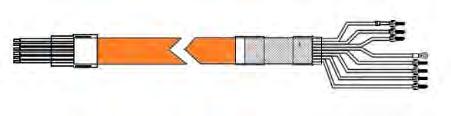
Cable reference : CC3UA1D1R0xxx
Feedback cable 6537P0059
Male 15 pins SUB-D connector reference 220029P0040
SUB-D cover reference 220029P0039
Cable
Cable reference : CC3UR1D1R0xxx
Feedback cable 6537P0059
Male 15 pins SUB-D connector reference 220029P0040
SUB-D cover reference 220029P0039
Cable arrangement :
Cable reference : CS5UA1D1R0xxx
Feedback cable 6537P0059
Male 15 pins SUB-D connector reference 220029P0040
SUB-D cover reference 220029P0039
Cable arrangement :
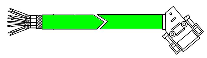
Cable reference : CS1UA1D1R0xxx
Feedback cable 6537P0059
Male 9 pins SUB-D connector reference 220029P0020
SUB-D cover reference 220029P0039
Pins reference 220029P0021
Cable arrangement :
Cable reference : CS2UR1D1R0xxx
Feedback cable 6537P0059
Male 9 pins SUB-D connector reference 220029P0020
SUB-D cover reference 220029P0039
Pins reference 220029P0021 Cable
For other drive, you can assembly cable and plug by soldering with part number on the tab below:
Feedback Sensor
Resolver
Hiperface Encoder
EnDat Encoder
Cable reference (C2 / 100°C)
6537P0059
Cable reference :
CS4UQ1D1R0xxx for current ≤ 12Amps Power cable 6537P0057
CS4UQ2D1R0xxx for current ≤ 24Amps Power cable 6537P0058
Cable

Cable reference :
CC3UQ1D1R0xxx for current ≤ 12Amps Power cable 6537P0057
CC3UQ2D1R0xxx for current ≤ 24Amps Power cable 6537P0058
Cable reference :
CS5UQ1D1R0xxx for current ≤ 12Amps Power cable 6537P0057
CS5UQ2D1R0xxx for current ≤ 24Amps Power cable 6537P0058
Cable
Cable reference :
CS2UQ1D1R0xxx for current ≤ 12Amps Power cable 6537P0057
CS2UQ2D1R0xxx for current ≤ 24Amps Power cable 6537P0058
Cable arrangement :
For other drive, you can assembly cable and plug by soldering with part number on the tab below:
Ampacity Cable reference (C2 / 100°C)
Current ≤ 12Amps @40°C
Current ≤ 9Amps @60°C 6537P0057
Current ≤ 24Amps @40°C
Current ≤ 17Amps @60°C
Caution: The holding brake is used to completely immobilize the servomotor under load. It is not designed to be used for repeated dynamic braking ; dynamic braking must only be used in the case of an emergency stop and with a limited occurance depending on the load inertia and speed.
The standard brake power supply is 24 Vcc DC ± 10%. Follow the polarity and the permissible voltage, and use shielded cables. A 220 µF capacitor avoids untimely braking if the 24 V voltage is disturbed by the external relay. Check the voltage value once this capacitor has been fitted. The RC network (220 Ω, 0.1 µF) is needed to eliminate interference produced by the brake coil. Position the contactor in the DC circuit to reduce brake response times. Follow the connection instructions taking the brake polarisation into account.
Table with typical values
All servomotors are strictly controlled during manufacturing, before shipping. While receiving it, it is necessary to verify motor condition and if it has not been damaged in transit Remove it carefully from its packaging. Verify that the data written on the label are the same as the ones on the acknowledgement of order, and that all documents or needed accessories for user are present in the packaging.
Warning: In case of damaged material during the transport, the recipient must immediately make reservations to the carrier through a registered mail within 24 h.
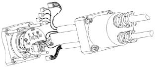
The servomotors EX8 are equipped with two lifting rings intended for handling.
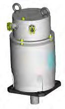
Caution: Use only servomotors lifting rings, if present, or slings to handle the motor. Do not handle the motor with the help of electrical cables, connectors and water inputs/outputs, or use any other inappropriate method.
The drawings below show the correct handling procedure.
DANGER: Choose the correct slings for the motor weight. The two slings must the same length and a minimum angle of 50° has to be respected between the motor axis and the slings.
Before being mounted, the motor has to be stored in a dry place, without rapid or important temperature variations in order to avoid condensation
During storage, the ambient temperature must be kept between -20 and +60°C.
If the torque motor has to be stored for a long time, verify that the shaft end, feet and the flange are coated with corrosion proof product.
After a long storage duration (more than 3 month), run the motor at low speed in both directions, in order to blend the bearing grease spreading.
4.2.1. Mounting
Foundation must be even, sufficiently rigid and shall be dimensioned in order to avoid vibrations due to resonance. Before bolting the motor, the foundation surface must be cleaned and checked in order to detect any excessive height difference between the motor locations. The surface variation shall not exceed 0,1 mm. In all cases, we recommend using shims in order to compensate small irregularities.
Caution: The user bears the entire responsibility for the preparation of the foundation.
The table below gives the average tightening torques required regarding the fixing screw diameter. These values are valid for both motor’s feet and flange bolting.
Warning: After 15 days, check all tightening torques on all screw and nuts.
Once the motor is installed, it must be possible to access the wiring, and read the manufacturer’s plate. Air must be able to circulate around the motor for cooling purposes. Clean the shaft using a cloth soaked in white spirit or alcohol. Pay attention that the cleaning solution does not get on to the bearings. The motor must be in a horizontal position during cleaning or running.
Caution: Do not step on the motor or the cable glands.
Caution: Always bear in mind that some parts of the surface of the motor can reach a temperature of 135°C
The operation life of servomotor bearings depends largely on the care and attention given to this operation
In the event that the servomotor shaft has a cotter pin, make sure that the coupling components have been balanced correctly without the cotter pin, the servomotor having been balanced with its cotter pin.
Prohibit any impact on the shaft and avoid press fittings which could mark the bearing tracks. If press fitting cannot be avoided, it is advisable to immobilize the shaft in motion; this solution is nevertheless dangerous as it puts the resolver at risk.
Use the thread at the end of the shaft in accordance with the diagram for fitting pulleys or accessories. It is possible to put pressure on the shoulder of the shaft located in front of the bearing.
In the event that the front bearing block is sealed by a lip seal which rubs on the rotating section (version IP 65), we recommended that you lubricate the seal with grease thus prolonging its operational life.
In the event that the drive system uses a pulley and belt, the drive pulley must be fixed as close as possible to the flange. The pulley diameter is to be selected so that the radial load does not exceed the limits given in the catalog.

CAUTION: Any equipment such as gearbox, mechanical speed drives, brakes, forced ventilation, integrated frequency converters, sensors, actuators, etc. associated with the motor must also have ATEX certification.
Warning : a misalignment of the coupling device makes stress and load on the motor shaft depending the rigidity of the installation The variations of the temperature makes stress and load due to the dilatation. These loads (axials and radiale) do not exceed the load written (§ 3.5).
Warning : The misalignment of the coupling device makes vibration who can realize a destruction of the motor shaft.
We cannot be held responsible for wear on the drive shaft resulting from excessive strain.
Danger: Check that the power to the electrical cabinet is off prior to making any connections.
Caution: The wiring must comply with the drive commissioning manual and with recommended cables.
Danger: The motor must be earthed by connecting to an unpainted section of the motor.
Caution: After 15 days, check all tightening torques on cable connection.
Please, read §3.8 "Electrical connection" to have information about cable connection Many useful informations are already available in the drive documentations.
Danger: before any intervention the drive must be stopped in accordance with the procedure.
Caution: It is forbidden to disconnect the Encoder cable under voltage (high risk of damage and sensor destruction).
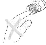
Warning: Always wear an antistatic wrist strap during encoder handling.
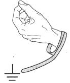
Warning: Do not touch encoder contacts (risk of damage due to electrostatic discharges ESD.
4.3.3.
4.3.3.1.


The safe torque off function is an alternative solution for the motor temperature monitoring.
The safe torque off function in accordance with the standards EN ISO 13849-1 : 2006 and EN 61800-5-2 : 2006 is an electronic system set up on some drives certified by a notified body. This is an unlocked input placed on the drive that must be connected (see the commissioning and use manual of the drive).

The servomotors EX are equiped with a thermal protection which is checked by a safety analysis and is a key element of the ATEX/IECEx safety. It is possible to connect this protection to the unlocked input or through a safety system in accordance to the drive specifications. This connection allows to maintain the drive power on, but disable the motor after the activation of the thermal protection.
After an activation of this security device, the system must not restart automatically and without a checking of the installation.
In all cases, the connection of this device must be checked and certified by a notified body.
4.3.4. Cable glands informations (Only ATEX/IECEx)
4.3.4.1. Technical data
M16 Cable glands ADE N°5 : Torque value for the cap = 12,5 N.m
Torque value for the connection module = 0,5 N.m
M20 Cable gland ADE N°6 : Torque value for the cap = 20 N.m
Torque value for the connection module = 0,5 N.m

The cables (Feedback or power cable) is a choice for end user and must be conform local state regulations.
The end user will comply with local state regulations for his installation and he will make the UL certification for his installation
The end user will determine which kind of connections and/ or conduits will be used.
Warning : Installers use any wiring other than that shown in the diagrams in §4.3.3. “Connection diagrams” at their own risk; Parker cannot be held responsible for unauthorized wiring. Make sure that the characteristics of the contactors shown in these diagrams are strictly followed according to the drive current
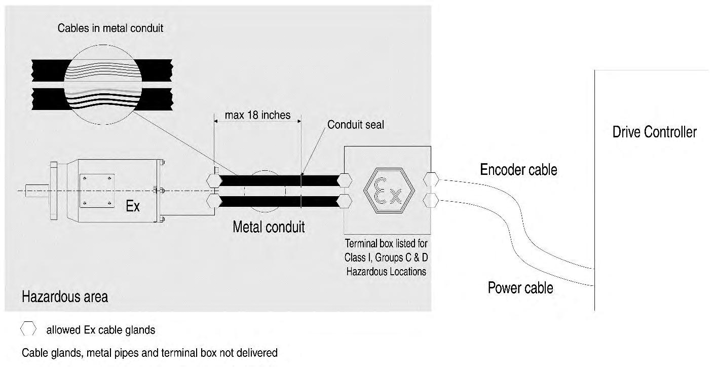
CAUTION : the drive associated with the motor must be outside the explosive area (hazardous area).
Warning : the conduit seal must be required within 18 inches of the motor.
Connection of the UL motor:
DANGER: The installation, commission and maintenance operations must be performed by qualified personnel, in conjunction with this documentation.
The qualified personnel must know the safety (C18510 authorization, standard VDE 0105 or IEC 0364) and local regulations.
They must be authorized to install, commission and operate in accordance with established practices and standards.
Please contact PARKER for technical assistance.
Danger: before any intervention the motor must be disconnected from te power supply.
Due to the permanent magnets, a voltage is generated at the terminals when the motor shaft is turned
If a screw assembly of the enclosure need to be replaced, the new screw will must be quality 8.8 or higher. For the EX8 in UL version the screw must be quality 14.9 or higher.
If the motor is used in dust explosive atmospheres, do not forget to do a regular cleaning in order to avoid the deposits of dusts.
Clean the motor
Motor inspection (vibration changes, temperature changes, tightening torques on all scews)
Cable inspection, no degradation (colour, flexibility, cracks…)
Bearing replacement
Every year
Every year
Every year
Every 20 000h
The Ex motors of Parker Hannifin France has a traceability on the frameprood enclosure compotents. It is forbidden to replace on of these components without consulting Parker Hannifin.
If a cover exchange between two identical motors is required, the customer must make a new traceability on these components. To make the traceability, the customer must refer to the number written on the cover.
In accordance with the standards for explosive atmospheres, find below the detail of the ATEX/IECEx flameproof joints
Some symptoms and their possible causes are listed below. This list is not comprehensive. Whenever an operating incident occurs, consult the relevant servo drive installation instructions (the troubleshooting display indications will help you in your investigation) or contact us at: http://www.parker.com/eme/repairservice
You note that the motor does not turn by hand when the motor is not connected to the drive.
You have difficulty starting the motor or making it run
Check there is no mechanical blockage or if the motor terminals are not short-circuited.
Check the power supply to the brake.
Check on the fuses, the voltage at the terminals (there could be an overload or the bearings could be jammed), also checks on the load current.
Check the power supply to the brake (+ 24 V ± 10 %) and its polarity.
Check on any thermal protection, its connection and how it is set in the drive
Check on the servomotor insulation (if in doubt, carry out hot and cold measurements).
The minimum insulation resistance value measured under a max. 50V DC is 50 MΩ:
Between the phase and the casing
Between the thermal protection and the casing
Between the brake coil and the casing
Between the resolver coils and the casing.
You find that the motor speed is drifting
You notice that the motor is racing
You notice vibrations
Reset the offset of the servoamplifier after having given a zero instruction to the speed setpoint input.
Check the speed setpoint of the servo drive.
Check you are well and truly in speed regulation (and not in torque regulation).
Check the encoder setting
Check on the servomotor phase order: U, V, W
Check the encoder and tachometer connections, the earth connections (carefully) and the earthing of the earth wire, the setting of the servo drive speed loop, tachometer screening and filtering.
Check the stability of the secondary voltages.
Check the rigidity of the frame and motor support.
You think the motor is becoming unusually hot
It may be overloaded or the rotation speed is too low : check the current and the operating cycle of the motor.
Check if the mounting surface is enough or if this surface is not a heat source – see §3.6 cooling.
Friction in the machine may be too high :
- Test the motor current with and without a load.
- Check the motor does not have thermal insulation.
- Check that there is no friction from the brake when the brake power is on.
You find that the motor is too noisy
Several possible explanations : Unsatisfactory mechanical balancing
There is friction from the brake: mechanical jamming
Defective coupling
Loosening of several pieces
Poor adjustment of servo drive or position loop : check rotation in open loop
