Rev. 2 Page 1/24
Date: 13.06.2016
Lucifer EPP4 Pressure Regulator
Installation and Setting Instructions
Lucifer EPP4 Druckregler
Einbau- und Einstellanleitung
Régulateur de pression Lucifer EPP4 Instructions d’installation et de réglage
Regolatore di pressione Lucifer EPP4 Istruzioni di installazione e regolazione
EPP4 Pressure Regulator
Ref. No. P4CG4461...
P4CG4465...
P4CG6161...
P4CG9161...

II 3 G / D
Ex nAc IIC T4
Ex tc IIIB T130°C – IP54
Tamb. : 0 ÷ 50°C
PORT CONNECTIONS PNEUMATISCHE ANSCHLÜSSE RACCORDEMENTS COLLEGAMENTO ATTACCHI
RECOMMENDED MOUNTING POSITION: Upright, with the electronics on top.
EMPFOHLENE EINBAULAGE:
Aufrecht stehend, Elektronik oben.
POSITION DE POSE RECOMMANDEE : Verticale, électronique en haut.
POSIZIONE DI MONTAGGIO
RACCOMANDATA:
Verticale, con l’elettronica in alto.
(Outlet port) (Ausgang) (Sortie) (Uscita)
(Exhaust) (Entlüftung) (Echappement) (Scarico)
A R
Max
Note: Use normalised connectors for ports P, A, R
Hinweis: Für Anschlüsse P, A, R genormte Verschraubungen
verwenden
Note : Utilisez les raccords normalisés pour les orifices P, A, R
Nota: usare connettori normalizzati per gli attacchi P, A, R
DESCRIPTION
BESCHREIBUNG
DESCRIPTION
DESCRIZIONE
(Inlet) (Eingang) (Entrée) (Ingresso)
Manual torque 1,5…2,5 Nm (M12)
Anzugsmoment 1,5…2,5 Nm (M12)
Couple manuel 1,5…2,5 Nm (M12)
Serraggio manuale 1,5…2,5 Nm (M12)
Max. Inlet pressure. Eingangsdruck max. Pression d’entrée maximale. Pressione di ingresso max.
P4C.4461 12 bar
P4C.4465 12 bar
P4C.6161 12 bar
P4C.9191 12 bar
Inlet pressure must be at least 1 bar higher than regulated pressure. Der Eingangdruck muss mindestens 1 bar höher sein als der benötigte Regelbereich.
PLa pression d’entrée doit être d’au min. 1 bar supérieure à la pression réglée
La pressione di ingresso deve essere maggiore di almeno 1 bar della pressione regolata.
P , A , R: torques max. 24 Nm (G1/2, G1, G2)
P , A , R: Drehmoment max. 24 Nm (G1/2, G1, G2)
P , A , R : couples max. 24 Nm (G1/2, G1, G2)
P , A , R: coppie max. 24 Nm (G1/2, G1, G2)
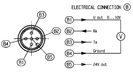
Plug B Information/Programming (with protection cap)
Stecker B Information/Programmierung (mit Schutzkappe)
Connecteur B : Information/ Programmation (avec bouchon de protection)
Connettore B Informazione/Programmazione (con cappuccio di protezione)
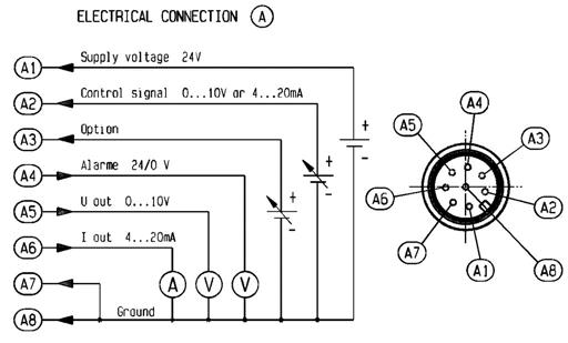
Plug A Control
Stecker A Versorgung/Steuersignal
Connecteur A : Commande
Connettore A Controllo
Body Körper Corps Corpo
ACCESSORY
To order separately Only for P4C.4…
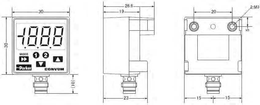
DIMENSIONS ABMESSUNGEN DIMENSIONS DIMENSIONI

INSTALLATION AND ELECTRICAL CONNECTIONS INSTALLATION
Before connecting the regulator EPP4, pay attention to the following instructions:
Connect the regulator as close as possible to the apparatus which will be regulated (resulting in higher precision and shorter response times);
Piping section of pressure supply should be sufficiently large;
Connect the air filter (50µ, Dew point 2°C) upstream from the regulator, and a lubrificator if necessary, downstream;
It is recommended to mount the regulator in a vertical position, electronic on top.
Set up the inlet pressure (max.: see page 2).
Connect the regulator to the pneumatic network.
Connect the pressure supply on the inlet port P and the regulation circuit with the outlet port A.
Fluid: lubricated (1 gr/m3 maxi) or non lubricated air and neutral gas
It is recommended to use a silencer in the exhaust R.
ELECTRICAL CONNECTIONS
Power supply
DC – Supply 24 V 15 %
In case of rectified voltage supply (from AC to DC) the residual ripple should be smaller than 1V
Disconnect the installation prior to any intervention on the electrical supply cable. Do not invert polarity.
The main connector (A) adopted is a standard 8 pole-M12:
The female connector to mount is the 8 pole M12 connector (IEC 61076-2-101 model LF).
Example:
Parker 496796
http://www.parker.com/
The information/programming connector (B) is a standard 5 pole M12 connector:
The female connector to mount is the 5 pole M12 connector (IEC 61076-2-101 model LF).
For safe use, please ensure the connectors are well mounted, the bellow protection mode must be followed.
Use only straight connectors to keep access free for both connectors
APPROVAL
The EPP4 regulators are in conformity with the ATEX , EMC and RoHS directives for the applications in zone 2 and 22..
II 3 G / D
Ex nAc IIC T4
Ex tc IIIB T130°C – IP54
Tamb. : 0 ÷ 50°C
EPP4 SETTING INSTRUCTIONS
The EPP4 regulators are fully adjusted and quality controlled at the factory to obtain standard specifications.
Here are the main factory settings:
Control signal: 0 to 10 Volt or 4 to 20mA corresponding to an output pressure range of, for example, 0 to 10 bar. (1V / 1 bar or 5,6mA / 1 bar)
REGULATION
Hysteresis: This value is adjusted in order to obtain an inaudible correction of the two 2-way solenoid pilots when there is no change of the control signal.
P4CG4461... < 100 mBar
P4CG4465... < 100 mBar
P4CG6161... < 100 mBar
P4CG9161... < 100 mBar
Forced exhaust:
The EPP4 regulator is equipped with an electronic safety circuit which automatically drops the output pressure at 0 bar when the control signal is below 50 mV or 4.1 mA. For safety reasons, it is recommended to reset the control signal at 0 bar before re-connecting the supply voltage (24VDC).
MAINTENANCE
The EPP4 does not require any maintenance. However the quality of used air should be checked periodically. Use current product to clean EPP4.
TROUBLE SHOOTING
Without removing the EPP top cap:
Record : - EPP type
- Manufacturing date
- Input pressure
Check : - Ports thread (P, A, R) quality

- Correct contact plastic cover / regulator body
- Correct pins level / position in the M12 plug
- Pilot exhaust orifice
TROUBLE SHOOTING
Problem Procedure
Unexpected behaviour
For other problems
Basic electrical controls See paragraph Electrical connections
Basic pneumatic controls See paragraph Port connections
Shut down 24 VDC. Wait 10 sec. Turn on 24VDC
Check the PLC signal
Contact your agent.
‘CALYS’ OPTION
This option should be used outside ATEX area.
Order No.: 496449 (Communication cable)
‘Calys' is a software to set all parameters of the EPP4 Comfort. The software is free of charge but you have to buy the specific cable 496449 to establish the communication with the EPP4.
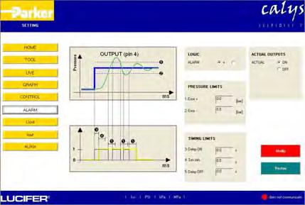
‘Calys’ has 3 levels of use, with 2 different passwords:
- View view only, no settings possible, no password
- Setting for basic settings and maintenance
- Factory only for authorized people, all settings
Parameters must be changed within the functional limits of the pressure regulators.
To use software Calys, you have to order specific communication cable ref 496449, then:
- You can download free Calys software from www.parker.com/fcde/support
- Install the software and use the Help File (pdf), it is the "?" on the page, up right corner. Select first your language (E, F, D, I), the Help File will be in the same language.
- Password needed to access "setting" level is "glage"
- Connect the EPP4 to your computer (see below)
- Re-set the EPP4 to your needs
Connection
Use the specific cable 496449 to connect the EPP4 to your computer:
RS-232
- M12 connector on EPP B connector
- Sub-D on computer
- Select the Port Com in the TOOL menu
- The “LED” bottom right corner becomes green if communication is ok
USB
Install the driver from the CD delivered with the USB kit. Read carefully the manual of the USB kit.
- M12 connector on EPP B connector
- Sub-D on USB adapter
- USB adapter on computer
- Select the Port Com in the TOOL menu
DISPLAY OPTION
This option should be used outside ATEX area.
Order No.: 496490
Compact and highly readable remote LED display, with bar and PSI scales.
The display is delivered in its own packaging with its specific manual.
1.5m cable included (M12 – M8)
Easy to fix with its 2 different mounting brackets.
Connection
-
-
The display is ready to use.
For safe use, please ensure the connectors are well mounted.
Specific Oxygen version ref P4CG4465.... Reminder on the oxygen use

This oxygen version reference is designed and assembled taking into account the general rules, the state of the art, to be applied on components that will be used with oxygen for industrial applications. This version is using only oxygen compatible materials, but the material type is not the only factor in a typical self ignition process. Flow speed for example, is a very important factor, and should be limited to 25 m/sec in the whole application (attention to valve restriction).
Filtration also should be carefully implemented and maintained (a filter partially blocked will increase the flow speed).
The final user should be familiar with these general rules that must be applied for oxygen applications, and is responsible of the real conditions of use of our regulators.
EINBAU UND ELEKTRISCHE ANSCHLÜSSE
EINBAU
Beachten Sie vor Anschluss des Reglers EPP4 die folgenden Anweisungen:
Schliessen Sie den Regler so nahe als möglich beim zu regelnden Apparat an (ergibt höhere Genauigkeit und kürzere Ansprechzeiten);
Der Rohrquerschnitt der Druckzuleitung sollte gross genug gewählt sein;
Schliessen Sie das Luftfilter (50µ, Taupunkt 2°C) auf der Eingangsseite des Reglers und wenn nötig einen DruckluftÖlen Schmiergerät auf der Ausgangsseite an;
Es wird empfohlen, den Regler in vertikaler Stellung, mit der Elektronik oben, einzubauen.
Stellen Sie den Eingangsdruck ein (max.: siehe Seite 2).
Schliessen Sie den Regler an das Druckluftnetz an. Schliessen Sie die Druckzuleitung an die Eingangsöffnung P und den Regelkreis an den Ausgang Austrittsöffnung A an.
Medium: geölte (max. 1 gr/m3) oder ungeölte Luft und neutrales
Gas
Es wird empfohlen, an Entlüftung R einen Schalldämpfer zu benutzen.
ELEKTRISCHE ANSCHLÜSSE
Stromversorgung
DC – Stromversorgung 24 V 15 %
Bei gleichgerichteter Spannungsversorgung (von AC in DC) muss die Restwelligkeit kleiner als 1V sein.
V
Elektrische Anschlussschemata
Vor allen Arbeiten am Stromzuleitungskabel die Anlage am Stromzuleitungskabel abtrennen. Polarität nicht umkehren.
Der gewählte Hauptstecker (A) ist genormt 8-polig M12:
Der zu montierende weibliche Stecker ist der 8-polige M12-Stecker (IEC 61076-2-101 Modell LF).
Beispiel:
Parker 496796 http://www.parker.com/
Der Informations-/Programmierungs-Stecker ist ein genormter 5Poliger M12-Stecker:
Der zu montierende weibliche Stecker ist der 5-polige M12-Stecker (IEC 61076-2-101 Modell LF).
Für eine sichere Verwendung stellen Sie bitte sicher, dass die Kabel fachgerecht verbunden wurden, Gemäss die Schutzbeschreibung unten definiert.
Benutzen Sie bevorzugt nur gerade Stecker, um den Zugang für beide Stecker frei zu halten.
ZULASUNG
Die Regler EPP4 sind in übereinstimmung mit den Richtlinien ATEX, EMV und RoHS für die Anwendungen in Zone 2 und 22.
II 3 G / D
Ex nAc IIC T4
Ex tc IIIB T130°C – IP54
Tumg. : 0 ÷ 50°C
EPP4 EINSTELLANLEITUNG
Die Regler EPP4 werden im Werk vollständig eingeregelt und der Qualitätskontrolle unterworfen, um die Standarddaten zu erfüllen. Dies sind die Standard Werkseinstellungen:
Steuersignal: 0 bis 10 Volt oder 4 bis 20mA entsprechend einem Ausgangsdruckbereich von zum Beispiel 0 to 10 bar. (1V / 1 bar oder 5,6mA / 1 bar)
EGELUNG
Hysterese: Dieser Wert wird so eingestellt, dass eine unhörbare Korrektur der zwei 2-Wege-Vorsteuermagnetventile erfolgt, wenn sich das Steuersignal nicht ändert.
P4CG4461... < 100 mBar
P4CG4465... < 100 mBar
P4CG6161... < 100 mBar
P4CG9161... < 100 mBar
Erzwungenes Ausblasen:
Der EPP4 Regler ist mit einem elektronischen Sicherheitskreis ausgestattet, der den Ausgangsdruck automatisch auf 0 bar abfallen lässt, wenn das Steuersignal unter 50 mV oder 4.1 mA sinkt. Aus Sicherheitsgründen wird empfohlen, das Steuersignal auf 0 bar zurückzustellen, bevor die Versorgungsspannung (24VDC) wieder eingeschaltet wird.
WARTUNG
Der EPP4 benötigt keinerlei Wartung. Jedoch wird empfohlen die Qualität der benutzten Luft periodisch zu kontrollieren werden.
Benutzen Sie für die Reinigung des EPP4 ein gängiges Produkt.
STÖRUNGSBEHEBUNG
Ohne die obere EPP-Schutzkappe zu entfernen:
Notieren : - EPP-Typ
- Fabrikationsdatum
- Eingangsdruck
Kontrollieren:- Anschlussgewinde (P, A, R) Zustand
- Korrekter Sitz der Plastikschutzkappe auf dem Reglerkörper
- Korrekte Ausrichtung der Stifte im M12-Stecker
- Vorsteuerungs-Entlüftung frei von Verschmutzungen
STÖRUNGSBEHEBUNG
Problem
Unerwartetes Verhalten
Bei anderen Problemen
Vorgehensweise
Elektrische Verbindung: Siehe Abschnitt „Elektrische Anschlüsse“
Pneumatische Anbindung: Siehe Abschnitt „pneumatische Anschlüsse“
24 VDC ausschalten. 10 Sek. Warten.. 24 VDC wieder einschalten
Das PLC-Signal kontrollieren
Setzen Sie sich bitte mit Ihrem Ansprechpartner in Verbindung.
‘CALYS’-OPTION
Diese Option sollte außerhalb ATEX-Bereich eingesetzt werden.
Bestellung Nr.: 496449 (Kommunikationskabel)
‘Calys' ist eine Software zur nachträglichen Einstellung aller Parameter des EPP4 Comfort. Die Software ist gratis, aber Sie benötigen ein spezielles Kabel 496449 kaufen, um die Kommunikation zum EPP4 zu herzustellen.

‘Calys’ hat 3 Hierarchieebenen mit 2 verschiedenen Passwörtern:
- View nur betrachten, keine Einstellung möglich, kein Passwort
- Setting für Grundeinstellung und Wartung
- Factory nur berechtigte Personen, alle Einstellungen
Parameter können nur innerhalb der Funktionsgrenzen des Druckreglers verändert werden.
Um die Software erhalten und nutzen zu können, benötigen Sie zuerst das Kommunikationskabel 496449 (separat zu bestellen) dann:
- Sie können sich Ihre kostenlose Version der Calys Software von www.parker.com/fcde/support herunterladen.
- Installieren Sie die Software und benutzen Sie die Hilfedatei (.pdf); sie ist das "?" auf der Seite in der oberen rechten Ecke. Wählen Sie die von Ihnen gewünschte Sprache (E, F, D, I), aus dann wird Ihnen die Hilfedatei in dieser Sprache angezeigt.
- Das benötigte Passwort für den Bereich "EINSTELLUNGEN" lautet: glage
- Schliessen Sie den EPP4 an Ihren Computer an (siehe weiter unten)
- Stellen Sie den EPPE4 Ihren Anforderungen entsprechend neu ein.
Anschluss
Benutzen Sie das ausschließlich das spezielle Kabel 496449, um den EPP4 an Ihren Computer anzuschliessen: RS-232
- M12-Stecker am Anschluss B des EPP
- Sub-D am Computer
- Wählen Sie die Port Com im TOOL-Menü
- Die “LED” in der unteren rechten Ecke wird grün, wenn die Kommunikation OK ist.
USB Installieren Sie den mit dem USB-Kit mitgelieferten Treiber.
Lesen Sie die Gebrauchsanweisung des USB-Kit sorgfältig.
- M12-Stecker am EPP B-Stecker
- Sub-D am USB-Adapter
- USB-Adapter am Computer
- Wählen Sie die Port Com im TOOL-Menü
DISPLAY OPTION
Diese Option sollte außerhalb ATEX-Bereich eingesetzt werden.
Bestellungs-Nr.: 496490 Kompakte und sehr leicht leserliche LED-Fernanzeige, mit bar- und PSI-Skalen.
Das Display wird in seiner separaten Verpackung mit einer entsprechenden Anleitung geliefert.
1.5m Kabel inbegriffen (M12 – M8)
Mit den seinen 2 verschiedenen Montagehaltern leicht montierbar.
Connection
- M12-Stecker an EPP B-Stecker
- M8-Stecker an Stecker des Displays
Das Display ist sofort funktionsbereit
Für eine sichere Verwendung stellen Sie bitte sicher, dass die Kabel fachgerecht verbunden wurden.
Sonderausführungen für Sauerstoff-Anwendungen, Teile-Nr.: P4CG4465....
Besondere Hinweise für den Gebrauch mit Sauerstoff
Diese Sauerstoff-Ausführungen wurden entwickelt und gefertigt entsprechend den technischen Grundregeln sowie dem aktuellen Stand der Technik, um bei Anwendungen mit Sauerstoff für industrielle Anwendungen verwendet zu werden.
Diese Ausführungen verwenden ausschliesslich Sauerstoff-kompatibles Material, aber die Materialbeständigkeit ist nicht der einzige Faktor für einen typischen Selbstentzündungsprozess. Strömungsgeschwindigkeit zum Beispiel ist ebenfalls ein wichtiger Faktor und sollte für die gesamte Anwendung auf einen Wert von maximal 25m/sec beschränkt werden (bitte beachten Sie eventuelle Einschränkungen des Druckreglers).
Eine geeignete Filtration sollte ebenfalls verwendet und ausreichend gewartet werden (ein teilweise verstopfter Filter erhöht ebenfalls die Strömungsgeschwindigkeit!)
Der Endanwender sollte mit diesen Grundregeln bei Anwendungen mit Sauerstoff vertraut sein, und ist verantwortlich für die tatsächlichen Rahmenbedingungen vor Ort bei der Benutzung unserer Druckregler.
INSTALLATION ET CONNEXIONS ELECTRIQUES
INSTALLATION
Avant de procéder à la connexion du régulateur EPP4, veuillez observer les instructions suivantes :
Positionner le régulateur le plus près possible de l’application (pour une meilleure précision et une réponse plus rapide);
La section du tuyau d’alimentation doit être suffisamment grande;
Connecter le filtre à air (50µ, Dew point 2°C) en amont du régulateur et si nécessaire un lubrificateur en aval;
Il est recommandé de monter le régulateur en position verticale, avec l’électronique en haut.
Régler la pression d’entrée (max.: voir page 2).
Raccorder le régulateur au réseau pneumatique.
Brancher la pression d’alimentation à l’orifice d’entrée P et le circuit réglé à l'orifice de sortie A.
Fluide : air lubrifié (1 g/m3 max) ou non lubrifié et gaz neutre
Il est recommandé de brancher un silencieux à l’échappement R.
CONNEXIONS ELECTRIQUES
Alimentation électrique
Alimentation DC 24 V 15 %
En cas d’alimentation en tension redressée (de AC à DC), l’ondulation résiduelle doit être inférieure à 1V.
Le connecteur mâle (A) prévu est du type standard M12 à 8 pôles :
Avant toute intervention sur le câble d’alimentation électrique, mettre l’installation hors tension. Ne pas inverser la polarité.
Le connecteur femelle correspondant est du type M12 à 8 pôles (IEC 61076-2-101 modèle LF).
Exemple :
Parker 496796 http://www.parker.com/
Le connecteur (B) d’information/programmation est du type standard M12 à 5 pôles :
Le connecteur femelle correspondant est du type M12 à 5 pôles (IEC 61076-2-101 modèle LF).
Pour une utilisation sûre, assurez-vous du montage correct des connecteurs, suivant le mode de protection défini ci-dessous.
N’utiliser que des connecteurs étroits afin de maintenir l’accès libre pour les deux connecteurs
APPROBATION
Les régulateurs EPP4 sont en conformité avec les directives ATEX, CEM et RoHS pour les applications en Zone 2 et 22.
II 3 G / D
Ex nAc IIC T4
Ex tc IIIB T130°C – IP54
Tamb. : 0 ÷ 50°C
INSTRUCTIONS DE REGLAGE EPP4
Les régulateurs de pression EPP4 ont été entièrement calibrés et contrôlés en usine de manière à obtenir les caractéristiques standards.
Calibrage U de sortie d’alarme Erreurd’alarme Temporis. d’alarme EN
Calibrage I de sortie Logique d’alarme Erreur+ Tonalité d’alarme min
Temporis. d’alarme HORS 0-10V ou 4-20mA 0-10bar 0-10bar 0-10V 0-10bar 4-20mA négative 0.5 bar 0.5 bar 0 0 0
Signal de commande : 0 à 10 Volt ou 4 à 20mA correspondant à une gamme de pression de sortie de par exemple
0
10
bar. (1V / 1 bar ou 5,6mA / 1 bar)
Hystérésis: Cette valeur est réglée de manière à obtenir une correction inaudible des deux pilotes à 2 voies en l’absence de signal de commande.
P4CG4461… < 100 mBar
P4CG4465… < 100 mBar
P4CG6161… < 100 mBar
P4CG9161… < 100 mBar
Echappement forcé :
Le régulateur EPP4 est équipé d’un circuit de sécurité électronique qui abaisse automatiquement la pression de sortie à 0 bar lorsque le signal de commande est inférieur à 50 mV ou 4.1 mA. Pour des raisons de sécurité, il est conseillé de réinitialiser le signal de commande avant de reconnecter la tension d’alimentation (24VDC).
MAINTENANCE
Le régulateur EPP4 ne nécessite aucun entretien. Toutefois la qualité de l’air doit être vérifiée périodiquement. Utiliser des produits courants pour nettoyer l’EPP4.
DEPANNAGE
Sans enlever le capot supérieur de l’EPP :
Noter : - le type EPP
- la date de fabrication
- la pression d’entrée
Vérifier : - l’état des filetages de raccordement (P, A, R)
- le bon contact entre couvercle plastique et corps du régulateur
- le niveau / la position correcte des contacts de la fiche M12
- l’orifice d’échappement pilote
DEPANNAGE
Problème Procédure
Comportement intempestif
Pour d’autres problèmes
Contrôles électriques de base: voir le paragraphe Connexions électriques
Contrôles pneumatiques de base: voir le paragraphe Raccordements
Couper l’alimentation 24 VDC. Attendre 10 sec. puis réenclencher le 24VDC
Vérifier le signal PLC
Contactez votre agent.
OPTION ‘CALYS’
Cette option doit être utilisée hors zone ATEX. No de commande : 496449 (câble de communication)
‘Calys' est un logiciel permettant de régler tous les paramètres de l’EPP4 Comfort. Ce logiciel est gratuit mais vous devez acheter le câble spécifique 496449 pour établir la communication avec l’EPP4.
‘Calys’ comporte 3 niveaux d’utilisation avec 2 mots de passe différents :
- Visualisation aperçu seulement, pas de réglages possibles, pas de mot de passe
- Réglage pour les réglages de base et de maintenance
- Usine seulement pour les personnes autorisées, tous les réglages
Les paramètres doivent être modifiés en respectant les limites fonctionnelles des régulateurs de pression.
Pour utiliser le logiciel, vous devez d’abord commander le câble de communication 496449, et ensuite:
- Télécharger gratuitement le logiciel Calys depuis l’adresse www.parker.com/fcde/support
- Installez le logiciel et utilisez le fichier Aide (pdf); c'est le "?" en haut de la page dans le coin droit. Choisissez votre langue (E, F, D, I) et le fichier Aide sera dans la même langue.
- L’accès au niveau « Réglage » nécessite le mot de passe : glage
- Connectez l’EPP4 à votre ordinateur (voir ci-dessous)
- Réinitialisez l’EPP4 en fonction de vos besoins
Connexion
Utilisez le câble spécifique 496449 pour connecter l’EPP4 à votre ordinateur :
RS-232
- Raccordez le connecteur M12 au connecteur EPP B
- Raccordez le connecteur Sub-D à l’ordinateur
- Sélectionnez le port COM dans le menu OUTILS
- Le “LED” du coin inférieur droit devient vert si la communication est établie
USB
Installez le pilote à partir du CD délivré avec le kit USB. Lisez attentivement le manuel du kit USB.
- Raccordez le connecteur M12 au connecteur EPP B
- Raccordez le connecteur Sub-D à l’adaptateur USB
- Raccordez l’adaptateur USB à l’ordinateur
- Sélectionnez le port COM dans le menu OUTILS
OPTION AFFICHEUR
Cette option doit être utilisée hors zone ATEX.
No de commande: 496490
Afficheur à distance à LED, compact, facilement lisible, avec échelles bar et PSI
L’afficheur est livré dans son propre emballage avec son mode d’emploi spécifique.
Câble de 1.5m inclus (M12 – M8)
Facile à poser grâce à ses 2 supports de montage différents.
Connection
- Raccordez le connecteur M12 au connecteur EPP B
- Raccordez le connecteur M8 au connecteur de l’afficheur
L’afficheur est prêt à être utilisé.
Pour une utilisation sûre, assurez-vous du montage correct des connecteurs.
Version spéciale Oxygène ref P4CG4465.... Rappels sur l’utilisation de l’Oxygène
Cette version oxygène a été conçue et assemblée en prenant en compte les règles générales, l’état de l’art, qui doit être appliqué pour les composants qui seront utilisés avec de l’oxygène dans le cadre d’applications industrielles.
Cette version n’utilise que des matériaux reconnus compatibles avec l’oxygène, mais le type de matériau n’est pas le seul facteur à prendre en compte dans le cas d’une combustion spontanée. La vitesse d’écoulement du fluide par exemple, est un facteur très important, et doit être limité à 25m/sec dans toute l’installation (attention aux zones de restriction).
La filtration doit être effectuée également avec précaution, et doit être bien entretenue (un filtre partiellement bouché va augmenter la vitesse du fluide).
L’utilisateur final devrait connaître ces règles générales qui doivent être appliquées pour les applications oxygène, et est responsable des conditions réelles d’utilisation de nos régulateurs.
INSTALLAZIONE E COLLEGAMENTI ELETTRICI
INSTALLAZIONE
Prima di collegare il regolatore EPP4, osservare le seguenti istruzioni:
Collegare il regolatore il più vicino possibile alla macchina da regolare (maggiore precisione e tempi di risposta più brevi);
La sezione dei tubi di alimentazione pneumatica dovrebbe essere sufficientemente ampia;
Collegare il filtro dell’aria (50µ, punto di rugiada 2°C) a monte del regolatore e un lubrificatore, se necessario, a valle;
Si raccomanda di montare il regolatore in posizione verticale, con l’elettronica in alto.
Impostare la pressione di ingresso (max. come pagina 2).
Collegare il regolatore alla rete pneumatica. Collegare l’alimentazione pneumatica all’attacco di ingresso P e il circuito di regolazione all’attacco di uscita A.
Fluido: lubrificato (1 gr/m3 max.) o aria non lubrificata e gas neutro Si raccomanda di usare un silenziatore nello scarico R.
COLLEGAMENTI ELETTRICI
Alimentazione elettrica
DC – Alimentazione 24 V 15 %
In caso di tensione rettificata (da AC a DC) l’ondulazione residua dovrebbe essere inferiore a 1V
Prima di qualunque intervento sul cavo di alimentazione elettrica, interrompere l’alimentazione. Non invertire la polarità.
Il connettore principale (A) adottato sul regolatore EPP4 è un M12 standard a 8 poli:
Il connettore femmina è un M12 a 8 poli (IEC 61076-2-101 modello LF).
Esempio: Parker 496796 http://www.parker.com/
Il connettore di informazione/programmazione (B) è un M12 standard a 5 poli:
Il connettore femmina da installare è un M12 a 5 poli (IEC 61076-2101 modello LF).
Per un uso sicuro, assicurarsi del corretto montaggio dei connettori, rispettare il modo di protezione come definito di seguito.
Utilizzare unicamente connettori diritti per lasciare libero l’accesso ai due connettori
APPROVAZIONE
Le EPP4 regolatori sono in conformità con le direttive ATEX, CEM e RoHS per le applicazioni in zona 2 e 22.
II 3 G / D
Ex nAc IIC T4
Ex tc IIIB T130°C – IP54
Tamb. : 0 ÷ 50°C
ISTRUZIONI DI REGOLAZIONE EPP4
Per ottenere le prestazioni standard, i regolatori EPP4 sono completamente preregolati e sottoposti a controllo qualità in stabilimento.
Quelle indicate nella tabella sottostante sono le principali regolazioni di fabbrica: Taratura segnale di controllo
Segnale di controllo:
Da 0 a 10 Volt oppure da 4 a 20mA corrispondenti a un campo di pressione di uscita di, per esempio, da 0 a 10 bar (1V / 1 bar oppure 5,6mA / 1 bar).
REGOLAZIONE
Isteresi: Questo valore è regolato in modo da ottenere una impercettibile correzione delle due elettrovalvole a 2 vie quando non c’è cambio del segnale di controllo.
P4CG4461... < 100 mBar
P4CG4465... < 100 mBar
P4CG6161... < 100 mBar
P4CG9161... < 100 mBar
Scarico forzato:
Il regolatore EPP4 è dotato di un circuito di sicurezza elettronico che automaticamente porta la pressione di uscita a 0 bar quando il segnale di controllo è inferiore a 50 mV o 4.1 mA
Per ragioni di sicurezza, si raccomanda di resettare il segnale di controllo a 0 bar prima di riallacciare la tensione di alimentazione (24VDC).
MANUTENZIONE
Il regolatore EPP4 non ha bisogno di alcun intervento di manutenzione. Tuttavia, è consigliabile controllare periodicamente la qualità dell’aria utilizzata.
Per pulire il regolatore EPP4, usare un normale prodotto in commercio.
RICERCA E RIPARAZIONE GUASTI
Senza rimuovere il cappuccio superiore del regolatore EPP:
Registrare: - Tipo EPP
- Data di fabbricazione
- Pressione di ingresso
Controllare: - Qualità filettatura attacchi (P, A, R)
- Corretto contatto copertura di plastica / corpo del regolatore
- Corretta posizione / livello pin nel connettore M12
- Attacco di scarico pilota
RIPARAZIONE DEI GUASTI
Problema
Procedura
Comportamento inaspettato Controlli elettrici di base. Vedere il paragrafo Collegamenti elettrici.
Controllo pneumatici di base. Vedere il paragrafo Collegamento attacchi. Spegnere il 24 VDC. Attendere 10 sec. Riaccendere il 24 VDC.
Controllare il segnale PLC.
Per altri problemi Contattare il proprio agente.
OPTIONAL ‘CALYS’
Questa opzione deve essere utilizzata al di fuori area ATEX.
Codice: 496449 (Cavo di comunicazione)
‘Calys' è un software che permette di impostare tutti i parametri dell’EPP4 Comfort. Il software è gratuito ma per stabilire il collegamento con l’EPP4 dovete acquistare il cavo specifico 496449.
‘Calys’ ha 3 livelli d’uso, con 2 diverse password:
- View (Visualizzazione) solo visualizzazione, nessuna regolazione possibile, nessuna password
- Setting (Regolazione) per regolazioni di base e manutenzione
- Factory (Stabilimento) solo per le persone autorizzate, tutte le regolazioni
I parametri devono essere cambiati entro i limiti funzionali dei regolatori di pressione.
Per avere il software dovete prima ordinare il cavo di comunicazione 496449, quindi:
- E' possibile scaricare il software calys gratuitamente dal sito: www.parker.com/fcde/support
- Installate il software e utilizzate l’Help File (pdf), si tratta di "?" in alto a destra. Selezionate innanzi tutto la lingua (E, F, D, I), e l’Help File sarà nella stessa lingua da voi selezionata.
- La password necessaria per entrare nella modalità "setting" è "glage"
- Collegate l’EPP4 al vostro computer (vedere sotto).
- Resettate l’EPP4 in funzione delle vostre esigenze.
Connessione
Utilizzare il cavo specifico 496449 per collegare l’EPP4 al vostro computer:
RS-232
- Connettore M12 sul connettore B dell’EPP.
- Sub-D sul computer.
- Selezionare Port Com nel menu TOOL.
- Il “LED” dell’angolo destro diventa verde se la comunicazione è a posto.
USB
Installare il driver dal CD fornito insieme con il kit USB. Leggere attentamente il manuale del kit USB.
- Connettore M12 sul connettore B dell’EPP.
- Sub-D sull’adattatore USB.
- Adattatore USB sul computer.
- Selezionare Port Com nel menu TOOL.
OPTIONAL DISPLAY
Questa opzione deve essere utilizzata al di fuori area ATEX.
Codice: 496490
Display a LED remoto, compatto e altamente leggibile, con scale bar e PSI.
Il display è spedito nella sua confezione contenente anche l’apposito manuale.
Cavo da 1,5 m incluso (M12 – M8)
Facile da installare con le sue 2 diverse staffe di montaggio.
Connection
- Connettore M12 sul connettore EPP B
- Connettore M8 sul connettore del display
Il display è pronto per l’uso.
Per un uso sicuro, assicurarsi del corretto montaggio dei connettori.
Versione specifica per Ossigeno rif. P4CG4465... Avvertenze sull'utilizzo per ossigeno
La versione per ossigeno di questo prodotto è disegnata e assemblata tenendo in considerazione le regole generali allo stato dell'arte da applicarsi a componenti che verranno utilizzati con fluido = ossigeno per applicazioni industriali. Questa versione utilizza unicamente materiali compatibili con ossigeno, ma il materiale non è l'unico elemento che può determinare un principio di combustione. La velocità del fluido, per esempio, è un fattore estremamente importante e dovrebbe essere limitata a 25 m/sec nell'applicazione (prestando attenzione alla restrizione della valvola).
Un processo di filtrazione dovrebbe essere inoltre implementato e soggetto a regolare manutenzione (un filtro parzialmente bloccato aumentarà la velocità del fluido).
L'utente finale deve essere a conoscenza delle regole generali che devono essere adottate in applicazioni con ossigeno ed è responsabile per le condizioni reali di utilizzo dei nostri regolatori.
EU Declaration of Conformity
EU Konformitätserklärung
Déclaration de Conformité UE
EU Dichiarazione di conformità
We: Parker Hannifin Manufacturing

Wir: Switzerland SA
Nous : 16, chemin Faubourg de Cruseilles
Noi : CH-1227 Carouge – Genève
declare under our sole responsibility that the product erklären in alleiniger Verantwortung, da das Produkt: déclarons sous notre seule responsabilité que le produit: Dichiariamo sotto la nostra responsabilità che i prodotti :
to which this declaration relates is in conformity with the following standards
Auf das sich diese Erklärung bezieht, mit der/den folgenden Norm(en) oder normativen Dokument(en) übereinstimmt:
Auquel se réfère cette déclaration est conforme à la (aux) normes(s) ou autre(s) document(s) normatif(s): Ai quali questa dichiarazione si riferisce sono conformi alle seguenti norme :
following the provisions of directives: gemä den Bestimmungen der Richtlinien: conformément aux dispositions de(s) directives: in base a quanto previsto dalle Direttivi :
ATEX: 2014/34/EU
EMC : 2014/30/EU
RoHS: 2015/863/EU
M. Lamine Bouchakhchoukha Certification & Patent ManagerThe data supplied in the Parker Catalogues are to be consulted, and pertinent accident prevention regulations are to be followed during product installation and use. Any unauthorized work performed on the product by the purchaser or by third parties can impair its function, and relieves us of all warranty claims and liability for any resulting damage.