


Hydraulic Power Units D, H, V-Pak and V-Pak Low Profile Series HY28-2661-CD/US Effective: Mar 31, 2016
WARNING - USER RESPONSIBILITY
FAILURE OR IMPROPER SELECTION OR IMPROPER USE OF THE PRODUCTS DESCRIBED HEREIN OR RELATED ITEMS CAN CAUSE DEATH, PERSONAL INJURY AND PROPERTY DAMAGE.
This document and other information from Parker-Hannifin Corporation, its subsidiaries and authorized distributors provide product or system options for further investigation by users having technical expertise.
The user, through its own analysis and testing, is solely responsible for making the final selection of the system and components and assuring that all performance, endurance, maintenance, safety and warning requirements of the application are met. The user must analyze all aspects of the application, follow applicable industry standards, and follow the information concerning the product in the current product catalog and in any other materials provided from Parker or its subsidiaries or authorized distributors.
To the extent that Parker or its subsidiaries or authorized distributors provide component or system options based upon data or specifications provided by the user, the user is responsible for determining that such data and specifications are suitable and sufficient for all applications and reasonably foreseeable uses of the components or systems.
OFFER OF SALE
The items described in this document are hereby offered for sale by Parker-Hannifin Corporation, its subsidiaries or its authorized distributor This offer and its acceptance are governed by the provisions stated in the detailed "Offer of Sale" elsewhere in this document.
© Copyright 2016, Parker Hannifin Corporation. All Rights Reserved.
1
Corporation Hydraulic
Power
Marysville, Ohio USA HY28-2661-CD/US Contents Contents D, H and V-Pak Series Introduction .......................................................................................................................2-3 Ordering Information .......................................................................................................4-10 Installation Information .................................................................................................11-13 Technical Information ...................................................................................................14-30 H-Pak with DCP Introduction ...................................................................................................................32-33 Ordering Information.........................................................................................................6-8 Installation Information .......................................................................................................27 Safety & Technical Information.................................................................................... 34-40 V-Pak Low Profile Series Introduction ...................................................................................................................42-43 Ordering Information.....................................................................................................44-45 Installation Information .......................................................................................................46 Technical Information ...................................................................................................47-58 Additional Installation Information ........................................................................................59 Additional Technical Information ...........................................................................................60 Conversion Equations .............................................................................................................61 Offer of Sale .............................................................................................................................63 Hydraulic Power Units D, H and V-Pak Series
Parker Hannifin
Pump and
Systems Division
2
2 V8 302.8 (80) 41.6 - 136.7 (11.0 - 36.1) 5.6 - 30 (7 1/2 - 40) 207
*See pump/motor combination, maximum pressure charts. skaP-V seireS noitcudortnI Quick Reference Data Chart Pump Flow Electrical MPL eziS knaT pmuP (GPM) Motors Maximum* Model No Liters (Gallon) @ 1725 RPM KW (HP) Bar (PSI ) 2.01 - 4.3 )5( 9.81 skaP-D (0.9 - 2.7) 0.37 (0.5) - 2.24 (3) 207 (3000) H-Paks 37.9 (10), 75.7 (20), 113.6 (30), 151.4 (40) 3.4 - 36.3 (0.9- 9.6) 0.37 (0.5) - 14.9 (20) 207 (3000) V-Paks 37.9 (10), 75.7 (20), 113.6 (30), 151.4 (40) 7.6 - 59.1 (2.0 - 15.6) 1.5 (2) - 14.9 (20) 207 (3000) Introduction
Power Units D, H and V-Pak Series
Parker Hannifin Corporation Hydraulic Pump and Power Systems Division Marysville, Ohio USA HY28-2661-CD/US Catalog HY28-2661-CD/US Volume Control Vertical Power Units Parker Hannifin Corporation Hydraulic Pump Division Mar yville, Ohio USA
(3000)
Hydraulic
HY28-2661-CD/US Catalog HY28-2661-CD/US
skaP-V seireS noitamrofnI
Warranty
Vertical Power Units
Volume Control
Warranty
The hydraulic components on these Parker Power Units are warranteed for one year. This warranty may be extended to two years by using and properly maintaining Parker filters.
The hydraulic components on these Parker Power Units are warranteed for one year. This warranty may be extended to two years by using and properly maintaining Parker filters.
Installation Data:
See Installation/ Maintenance Manual for specific recommendations pertaining to start-up, system cleanliness, fluids, temperature and other important factors relative to proper installation and use of these power units.
Installation Data: See Installation/ Maintenance Manual for specific recommendations pertaining to start-up, system cleanliness, fluids, temperature and other important factors relative to proper installation and use of these power units.
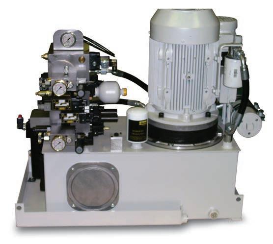
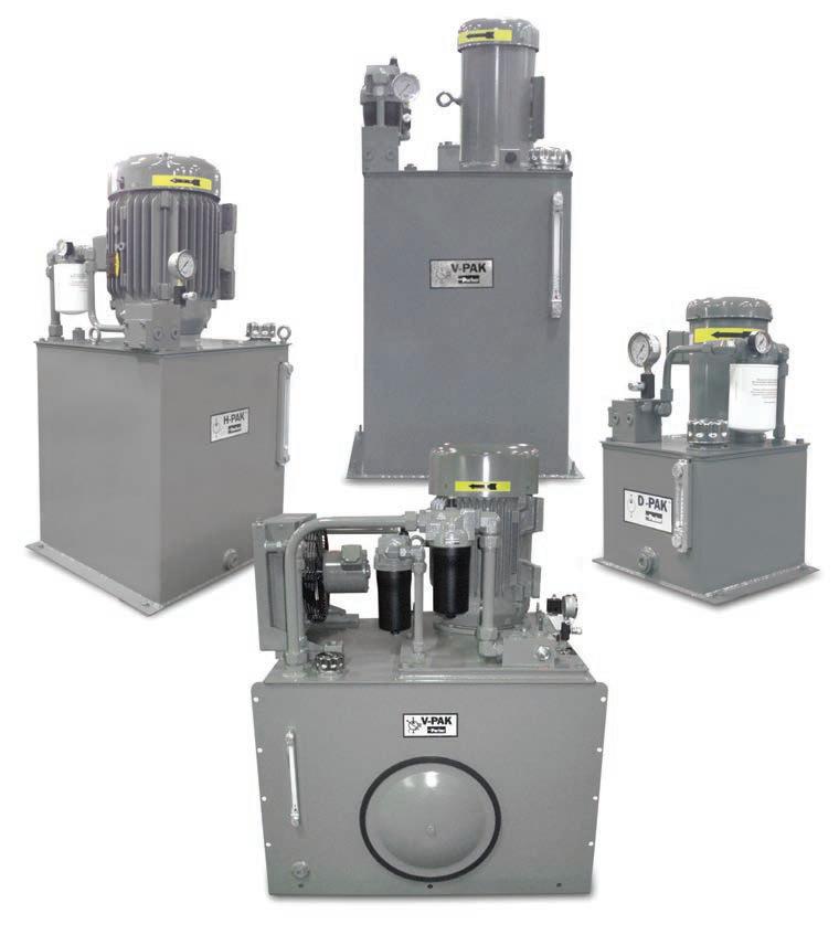
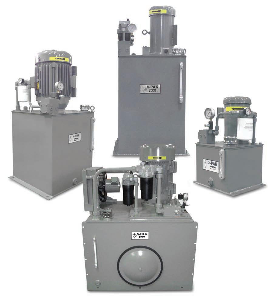
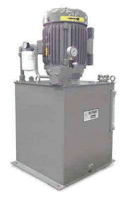
Standard Features
•Ver tical Design
•Submerged Pump
•Spare Return Ports
•Precision Pump Mounting Adapters
• Suction Strainer
•Glycerine Filled Pressure Gage with Shut Off
•Oil Level Gage with Thermometer
• Relief Valve
•Breather and Fill Cap
• SAE Drain Plug
• Parker Connector Technology
• Available with Digital Drives (See DCP Pak section of this catalog)
•
Schematic Symbol
(See DCP Pak section of this catalog)
Benefits
Benefits
•Saves Floor Space
• Quieter Operation, Elimination of Potential Leak Point
•Longer Pump Life
•Saves Floor Space • Quieter Operation, Elimination of Potential Leak Point
•Protects Pump from Contamination
•Improved Diagnostics
• Helps to Maintain Trouble-Free Per for mance
•Protects Against System Shock
•Easy To Fill Reservoir
•Prevents Leaks
•Longer Pump Life •Protects Pump from Contamination •Improved Diagnostics • Helps to Maintain Trouble-Free Per for mance •Protects Against System Shock •Easy To Fill Reservoir •Prevents Leaks
Schem
(Hydraulic Schematic - Basic Unit)
atic
Symbol (Hydraulic Schematic - Basic Unit)
Parker Hannifin Corporation Hydraulic Pump and Power Systems Division Marysville, Ohio USA
3
Parker Hannifin Corporation
Hydraulic Pump Division Mar yville, Ohio USA
3
SPARE RETURN SAE -12 M X “O” OPTION MANIFOLD “OMIT” OPTION COMP CONTROL V-PAK BASIC UNIT NO OPTIONS OR ACCESSORIES “OMIT” OPTION PUMP COMPENSATOR “O” OPTION MANIFOLD P P T A B T X X X SPARE RETURN SAE -12 M X “O” OPTION MANIFOLD D & H-PAK BASIC UNIT NO OPTIONS OR ACCESSORIES “O” OPTION MANIFOLD P P T A B T X X X Catalog HY28-2661-CD/US Volume Control Vertical Power Units
Hannifin
Hydraulic
Mar
Ohio USA 3 skaP-V seireS
Features
Design
Pump
Return Ports
Pump Mounting Adapters
Filled Pressure Gage with
Off
Gage with Thermometer
Relief Valve
and Fill Cap
Parker
Corporation
Pump Division
yville,
noitamrofnI Standard
•Ver tical
•Submerged
•Spare
•Precision
• Suction Strainer •Glycerine
Shut
•Oil Level
•
•Breather
Drain Plug
• SAE
• Parker Connector Technology
Available with Digital Drives
SPARE RETURN SAE -12 M X “O” OPTION MANIFOLD “OMIT” OPTION COMP CONTROL V-PAK BASIC UNIT NO OPTIONS OR ACCESSORIES “OMIT” OPTION PUMP COMPENSATOR “O” OPTION MANIFOLD P P T A B T X X X SPARE RETURN SAE -12 M X “O” OPTION MANIFOLD D & H-PAK BASIC UNIT NO OPTIONS OR ACCESSORIES “O” OPTION MANIFOLD P P T A B T X X X Introduction
D,
and V-Pak
Hydraulic Power Units
H
Series
Hydraulic
B D1VW001CN***D037 (26.5) Double (Spr. Ctr)
C D1VW004CN***D037 (26.5) Double (Spr. Ctr)
T D1VW008CN***D037 (26.5) Double (Spr. Ctr)
If
U1 .5 (.37) - 1725-56C-1
T1 1 (.75) - 1725-56C-1
T3 1 (.75) - 1725-56C-3 W G 56C (no motor)
D G 2 (1.5)-1725 - 56C-3*
D K 3 (2.2) - 1725-182TC*
W L 182TC/184TC (no motor) D = DUAL RATED * W = NO MOTOR **
Single phase electric motors are rated as follows: 115/230V, 1PH, TEFC - 60 Hertz 1800 RPM
Three phase electric motors are rated as follows: 208-230/460V, 3PH, TEFC - 60 Hertz 1800 RPM 1.15 SF
• Dual rated motors include the 60Hz ratings plus 190/380V 50Hz (1.5SF) 1450RPM 10:1CT/20:1VT INVERTER RATED UR/CSA/CSA EEV/CE
• Options G & K are dual rated as standard.
•• Use W prefix when no motor is required on unit.
When ordering, W must be followed by motor model code equivalent to frame size of motor to be used.
DO NOT USE “W” and “D” together i.e. 56C frame unit with no motor is called out “WG”.
B1* ExchangerRM-08-2-2
Air/Oil: 0.7 HP (52 kW) Rej. @ 3 GPM (11.4 LPM)
H Pressure Filter 15P110QXRS Microglass II Element Vis. Ind. – 50 PSI (3.4 bar) Bypass – 2 PSI (0.14 bar) Diff. @ 3 GPM (11.4 LPM)
K Check Valve Pump Outlet DT370MOMF05 5 PSI (0.34 bar) Cracking Pressure 7 PSI (0.48 bar) Diff. @ 3 GPM (11.4 LPM)
L Bypass Check (on Heat Exch) C1020S65 65 PSI (4.5 bar) Cracking Pressure
O Return Filter 12AT10C 45LPM (12 GPM)
R1 Combination Float/Temp. Switch N.O. Float Up 8767820-1
R2 Combination Float/Temp. Switch Float Up 876782-02
Cellulose Element Ind. Gage - 15 PSI (1.03 bar) Bypass Max. Oil Flow
Fixed Temp at 65°C (149°F) Close @ Low Level and/or 65°C (149°F) (N.O.)
Fixed Temp at 65°C (149°F) Open @ Low Level and/or 65°C (149°F) (N.C.)
*Heat rejection based on flow given with a 40°F differential between transfer medium.
4 HY28-2661-CD/US
D-Paks Ordering Information
Parker Hannifin Corporation Hydraulic Pump and Power Systems Division Marysville, Ohio USA
Power Units D-Paks D5 Code Pump Flow Used 0.9 331-9110-267
2.7
P Reservoir 18.9 Liters (5 Gal) Code Pressure Control Omit System Pressure Relief Valve Only B System Pressure Relief Valve with Unloading Valve
N.O. (Energize coil to close) J System Pressure Relief Valve with
Valve
N.O. (Energize coil to close) Code Porting Block/Subplate or Manifold Type Supply/Return Port or Actuator Port Size Other O Pressure and Return Port Block with Safety Relief Valve P & T Ports SAE-10 Str. Thr'd Convertible to S3 Option S3 D03 Single Station Subplate with Safety Relief Valve A & B Ports SAE-8 Str. Thr'd Spare P & T SAE-10 Ports M33 D03 Multistation Parallel Circuit Manifold with Safety Relief Valve A & B Ports SAE-8 Str. Thr'd Spare G Port SAE-6 Manifolds are mounted vertically. Bottom station is number 1. Code Manapak Control Valves Function Valve Model Number NFPA Mounting Pad Nominal Flow GPM (LPM) Circuit Symbol
1.3 331-9110-011 1.8 331-9110-010
331-9110-101
(2-Way 120VAC)
Unloading
(2-Way 24VDC)
1 Flow Control Meter-Out FM2DDKND037 (26.5) 3 Pilot Operator Check CPOM2DDND037 (26.5)
FunctionModel NumberTechnical Data
Manapak valves mounted in order of callout. First valve will be nearest DCV; last valve will be on manifold. Code Options and Accessories
Directional Control Valve Model Number NFPA Mounting Pad Nominal Flow GPM
Description Circuit Symbol
Code
(LPM)
= Omit if not required Pressure Control Pump Flow Electric Motor Manifold Directional Control Valve Manapak Control Valves• Options and Accessories
Units less valves will be supplied with station cover plates installed.
No Motor or Dual Rated Code
Motor Description
RPM
Phase
Electric
HP (KW) -
Frame
PT AB PT AB PT
D = Dual Rated• W = No Motor•• AB
HY28-2661-CD/US Notes Hydraulic Power Units D-Paks
5
Parker Hannifin Corporation Hydraulic Pump and Power Systems Division Marysville, Ohio USA
Reservoir
Code
H1* 10 (37.9)
H2 20 (75.7)
H3 30 (113.6)
H4 40 (151.4)
Reservoir Size Gallons (Liters)
If No Motor or Dual Rated Code
Hydraulic Power Units H-Paks
Electric Motor Description HP (KW) - RPM Frame Phase
N 10 (7.5) - 1725 - 215TC - 3
D N 10 (7.5) - 1725 - 215TC - 3 DUAL RATED
WP † 254TC (no motor)
P † 15 (11.2) - 1725 - 254TC - 3
DP † 15 (11.2) - 1725 - 254TC - 3 DUAL RATED
WS † 256TC (no motor)
Code Pressure Control*
Omit System Pressure Relief Valve Only
B System Pressure Relief Valve with Unloading Valve (2-Way 120VAC) N.O. (Energize coil to close)
J System Pressure Relief Valve with Unloading Valve (2-Way 24VDC) N.O. (Energize coil to close)
Code Pump Flow Used
0.9 331-9110-267
1.3 331-9110-011
1.8 331-9110-010
2.7 331-9110-101
3.2 334-9111-069
4.5 334-9111-068
5.1 334-9111-067
6.3 334-9111-048
8.1* 334-9111-065
9.6* 334-9111-049
U1 .5 (.37) - 1725-56C-1 T1 1 (.75) - 1725-56C-1
T3 1 (.75) - 1725-56C-3
W G 56C (no motor)
D G 2 (1.5)-1725 - 56C-3 DUAL RATED
D K 3 (2.2) - 1725-182TC DUAL RATED
W L 182TC/184TC (no motor)
L 5 (3.75) - 1725 - 184TC - 3
D L 5 (3.75) - 1725 - 184TC - 3 DUAL RATED
W M 213TC (no motor)
M 7.5 (5.6) - 1725 - 213TC - 3
D M 7.5 (5.6) - 1725 - 213TC - 3 DUAL RATED
W N 215TC (no motor)
Continued: top right.
S † 20 (14.9) - 1725 - 256TC - 3
DS † 20 (14.9) - 1725 - 256TC - 3 DUAL RATED
Single phase electric motors are rated as follows: 115/230V, 1PH, TEFC - 60 Hertz 1800 RPM
Three phase electric motors are rated as follows: 208-230/460V, 3PH, TEFC - 60 Hertz 1800 RPM 1.15 SF
• Dual rated motors include the 60Hz ratings plus 190/380V 50Hz (1.0SF) 1450RPM 10:1CT/20:1VT INVERTER RATED UR/CSA/CSA EEV/CE. 2Hp & 3Hp S.F.=1.15
• Dual rated motors except 2Hp & 3Hp may have longer than standard leadtime. Options G & K are dual rated as standard.
Consult factory for other motor speeds (RPM) and voltages.
†Available with H2, H3 and H4 tanks only.
•• Use W prefix when no motor is required on unit. When ordering, W must be followed by motor model code equivalent to frame size of motor to be used.
DO NOT USE “W” and “D” together i.e.: 182/184TC unit with no motor is called out “WL”.
Code Porting Block/ Subplate or Manifold Type
Supply/Return Port or Actuator Port Size Other
O Pressure and Return Port Block with Safety Relief Valve P & T Ports SAE-10 Str. Thr'd Convertible to S3 Option
S3 D03 Single Station Subplate with Safety Relief Valve A & B Ports SAE-8 Str. Thr'd Spare P
6 HY28-2661-CD/US
H-Paks Ordering Information
&
Ports S5 D05
Subplate
A
Ports SAE-10
M33 M35 D03
Parallel
A
M53 M55 D05
Parallel
A
Ports SAE-8
Manifolds are mounted vertically. Bottom
T SAE-10
Single Station
with Safety Relief Valve
& B
Str. Thr'd Spare P & T SAE-12 Ports
Multistation
Circuit Manifold with Safety Relief Valve
& B Ports SAE-8 Str. Thr'd Spare G Port SAE-6
Multistation
Circuit Manifold with Safety Relief Valve
& B
Str. Thr'd Spare G Port SAE-6
station is number 1. Pressure Control Pump Flow Electric Motor Manifold *Available up to 7.5 KW (10 HP) motor only. *Do not select a motor smaller than 2 Hp with these flow rates. = Omit if not required D = Dual Rated• W = No Motor••
Parker Hannifin Corporation Hydraulic Pump and Power Systems Division Marysville, Ohio USA
If No Motor or Dual Rated Code Electric Motor Description HP (KW) - RPM Frame Phase
HY28-2661-CD/US H-Paks Ordering Information
Hydraulic Power Units H-Paks
PFor DCP (inverter) options, see next page
B D1VW001CN***D03 7 (26.5) Double (Spr. Ctr)
C D1VW004CN***D03 7 (26.5) Double (Spr. Ctr)
F D3W1CN**D05 20 (75.7) Double (Spr. Ctr)
G D3W4CN**D05 15 (56.8) Double (Spr. Ctr)
T D1VW008CN***D03 7 (26.5) Double (Spr. Ctr)
W D3W8CN**D05 15 (56.8) Double (Spr. Ctr) Units less valves wil be supplied with station cover plates installed.
CodeFunction
1 Flow Control FM2DDKND03 7 (26.5)
2 Flow Control FM3DDKND05 12 (45.4)
3 Pilot Operator Check CPOM2DDND03 7 (26.5) 4 Pilot Operator Check CPOM3DDND05 12 (45.4)
*Manapak valves mounted in order of callout. First valve will be nearest DCV; last valve will be on manifold.
Code Function Model Number Technical Data
B1* Return Line Heat Exchanger RM-08-1-2 Air/Oil: .7 HP (0.52 kW), Rej. @ 7 GPM (26.5 LPM) 0.37 - 3.7 kW Motors only
B2* Return Line Heat Exchanger RM 190-1-2 Air/Oil: 1.5 HP (1.1 kW), Rej. @ 7 GPM (26.5 LPM) 5.6 - 11.2 kW Motors only
C *^ Return Line Heat Exchanger BS-401-A4-O-BR Water/oil: 4hP (3KW)Rej @ 5GPM Oil Flow 1:1 Flow ratio Max oil Flow 10GPM Includes 3/4" weld coupling for customer supplied device
E^ Water Valve/bulbwell 65253 + bulbwell + 3/4" weld coupling If ordered without option C this option will only include the 3/4" weld coupling.
H Pressure Filter 15P110QXRS Microglass II Element, Vis. Ind. - 50 PSI (3.49 bar) Bypass - 4 PSI (0.27 bar), Diff. @ 7 GPM (26.5 LPM) J 2" Weld coupling for customer supplied heater
K Check Valve Pump Outlet “DT” & “C” Series 5 PSI (0.34 bar) Cracking Pressure 25 PSI (1.72 bar) Diff. @ 15 GPM (56.8 LPM)
L Bypass Check (on Heat Exch) C1220S65(65 PSI) 4.5 bar Cracking Pressure
N Return Filter 40CN110B MICROGLASS ii Element, Vis 25PSI (1.72Bar) Indicator 3PSI (0.21Bar) Diff. @ 7GPM (26.5LPM)
O Return Filter 12AT10C 12 GPM (45 LPM) Cellulose Element, Ind. Gage - 15 PSI (1.03 bar) Bypass
R1 Combination Float/Temp. Switch N.O. Float Up 876782-01 Fixed Temp at 65°C (149°F) Close @ Low Level and/or 65°C (149°F) (N.O.)
R2 Combination Float/Temp. Switch Float Up 876782-02 Fixed Temp at 65°C (149°F) Open @ Low Level and/or 65°C (149°F) (N.C.)
*Heat rejection based on flow given with a 40°F differential between transfer medium.
^ May require longer than standard lead time.
Hydraulic Pump and Power Systems Division Marysville, Ohio USA
= Omit if not required
7
Parker Hannifin Corporation
Directional Control Valve Manapak Control Valves• Options and Accessories
Valve Model Number NFPA Mounting Pad Nominal Flow GPM (LPM) Circuit Symbol
Code Valve Model Number NFPA Mounting Pad Nominal Flow GPM (LPM) Description Circuit Symbol
AB PT AB PT AB PT
PT AB PT
AB
AB PT
Hydraulic Power Units H-Paks
Description
I Analog Speed Control (4-20mA) Unit will be configured to operate 500-2000 RPM from a 4-20mA input signal
V Analog Speed Control (0-10VDC) Unit will be configured to operate 500-2000 RPM from a 0-10VDC input signal
D Discrete Speed Control (3 inputs) Unit will be configured to operate at 8 discrete speeds based on combination of 3 inputs.
Q 2 Speeds Based on Torque Unit will run at 1800 RPM until motor torque Reaches 85% of NOM, them will go to 600 RPM.
S Soft Start Unit will be configured to run at 1800 RPM with a 2 sec accel ramp (0 to 1800 RPM in 2 secs)
16G-31-0070-BF-DT
16G-41-0040-BF-DT
16G-31-0100-BF-DT
8
Parker Hannifin Corporation Hydraulic Pump and Power Systems Division Marysville, Ohio USA HY28-2661-CD/US H-Paks Ordering Information
Code Configuration
HPVoltage Hp/Voltage AC 10 Part Numbers 2 2
Power
3 Phase
Incoming
230VAC
4
3 Phase
3 2
3 Phase
4
3
54
3
7.54
3
104
3 Phase
154
3
204
Power
3 Phase
Code Configuration Description 2*
4
*Only available for 2Hp &
Consult factory for single
applications DCP Inverter Drive From H-Pak Options & Accessories Control Configuraton Voltage (3
Code Configuration Omit End of Model Code \
Drive
per the following selections
Option Not Available on
Units Sample Model Code
Voltage
Option Include
Option
Incoming Power 460VAC
Incoming Power 230VAC
Incoming Power 460VAC
Phase 16G-41-0065-BF-DT
Incoming Power 460VAC
Phase 16G-41-0090-BF-DT
Incoming Power 460VAC
Phase 16G-42-0120-BF-DT
Incoming Power 460VAC
16G-42-0170-BF-DT
Incoming Power 460VAC
Phase 16G-43-0230-BF-DT
Incoming
460VAC
16G-43-0320-BF-DT
Incoming Power 230VAC 3 Phase 220-240V +/-15%
Incoming Power 460VAC 3 Phase 380-480V +/-10%/-15%
3Hp Drives
phase
Phase)
AC10
configured
DCP
1/2 & 1 Hp
H36.3NOPHKN\V4 Incoming Power 460VAC 3 Phase
Control
DCP
Reservoir
Bi-Pressure Remote Compensator, 24VDC
Bi-Pressure Remote Compensator with Low Pressure Standby
Remote Compensator with Low Pressure Standby, 24VDC
D = Dual Rated• W = No Motor••
If No Motor or Dual Rated Code
Electric Motor Description
HP (KW) - RPM Frame Phase
W G 56C (no motor)
D G 2 (1.5)-1725 - 56C-3 DUAL RATED
D K 3 (2.2) - 1725-182TC DUAL RATED
W L 182TC/184TC (no motor)
L 5 (3.75) - 1725 - 184TC - 3
D L 5 (3.75) - 1725 - 184TC - 3 DUAL RATED
W M 213TC (no motor)
M 7.5 (5.6) - 1725 - 213TC - 3
D M 7.5 (5.6) - 1725 - 213TC - 3 DUAL RATED
W N 215TC (no motor)
N 10 (7.5) - 1725 - 215TC - 3
D N 10 (7.5) - 1725 - 215TC - 3 DUAL RATED
WP † 254TC (no motor)
P † 15 (11.2) - 1725 - 254TC - 3
DP † 15 (11.2) - 1725 - 254TC - 3 DUAL RATED
WS † 256TC (no motor)
S † 20 (14.9) - 1725 - 256TC - 3
DS † 20 (14.9) - 1725 - 256TC - 3 DUAL RATED
Single phase electric motors are rated as follows: 115/230V, 1PH, TEFC - 60 Hertz 1800 RPM
Three phase electric motors are rated as follows: 208-230/460V, 3PH, TEFC - 60 Hertz 1800 RPM 1.15 SF
• Dual rated motors include the 60Hz ratings plus 190/380V 50Hz (1.0SF) 1450RPM 10:1CT/20:1VT INVERTER RATED UR/CSA/CSA EEV/CE. 2Hp & 3Hp S.F.=1.15
• Dual rated motors except 2Hp & 3Hp may have longer than standard leadtime. Options G & K are dual rated as standard.
Consult factory for other motor speeds (RPM) and voltages.
†Available with V2, V3 and V4 tanks only.
7 7 GPM (29.5 LPM)PVP16 - Std. Remote Compensator
* Specify in GPMDestroked Max. Volume – 2 GPM Min. 15 15.6 GPM (59 LPM)PVP33 - Std. Remote Compensator
** Specify in GPMDestroked Max. Volume – 8 GPM Min.
*Unless otherwise specified, units are shipped at max. flow rate 7.8 GPM (29.5 LPM) at 1800 RPM. When reduced flow setting is required, specify pump setting in .5 GPM (1.9 LPM) increments. Example: 5, 5.5, 6, 6.5 with a 2 GPM (7.6 LPM) minimum flow.
**Unless otherwise specified, units are shipped at max. flow rate 15.6 GPM (59 LPM) at 1800 RPM. When reduced flow setting is required, specify pump setting in .5 GPM (1.9 LPM) increments. Example: 11, 11.5, 12, 12.5 with a 8 GPM (30.3 LPM) minimum flow.
Example: V*12**-- = Std. Pump Destroked to 12 GPM (45.4 LPM)
V*A11.5**-- = Load Sense Pump Destroked to 11.5 GPM (43.5 LPM)
= Omit if not required
•• Use W prefix when no motor is required on unit. When ordering, W must be followed by motor model code equivalent to frame size of motor to be used.
DO NOT USE “W” and “D” together I.E: 182/184TC unit with no motor is called out “WL”.
9
V-Paks Ordering Information Hydraulic Power Units V-Paks Code Reservoir Size Gallons (Liters) V1* 10
V2 20
V3 30
V4 40
Omit Single
B
BJ
C
CJ
D
DJ
F
Code Porting Block/Subplate or Manifold Type Supply/Return Port or Actuator Port Size Other O Pressure and Return Port Block with Safety Relief Valve P & T Ports SAE-10 Str. Thr'd Convertible to S5 Option S3 D03 Single Station Subplate with Safety Relief Valve A & B Ports SAE-8 Str. Thr'd Spare P & T SAE-10 Ports S5 D05 Single Station Subplate with Safety Relief Valve A & B Ports SAE-10 Str. Thr'd Spare P & T SAE-12 Ports M33 M35 D03 Multistation Parallel Circuit Manifold with Safety Relief Valve A & B Ports SAE-8 Str. Thr'd Spare
Port
M53 M55 D05 Multistation Parallel Circuit Manifold with
Relief Valve A & B Ports SAE-8 Str. Thr'd Spare G Port
Manifolds are mounted
Bottom station
Control Pump Control Electric Motor Manifold *Available up to 10 HP
motor only. *A_SAE-6 sense port line will be supplied
**
Code Pump Control Omit
A* Load
Flow Control H** Horsepower
Pump Flow
Flow OR
Parker Hannifin Corporation Hydraulic Pump and Power Systems Division Marysville, Ohio USA HY28-2661-CD/US
(37.9)
(75.7)
(113.6)
(151.4) Code Pressure Control
Pressure Remote Compensator
Single Pressure Remote Compensator with Low Pressure Standby
Single Pressure Remote Compensator with Low Pressure Standby, 24 VDC
Bi-Pressure Remote Compensator
Bi-Pressure
Provision for Customer Supplied Remote Control Relief Valve
G
SAE-6
Safety
SAE-6
vertically.
is number 1. Pressure
(7.5 kW)
in topplate.
Horsepower setting will be at max. flow & pressure obtainable with motor selected. Lead time is four weeks for shaded items.
Std. Remote Compensator
Sense
Limiting
Reduced
Code Pump Flow Rate @1800 RPM Pump Used and Description
1 Flow Control
FM2DDKND037 (26.5)
2 Flow Control FM3DDKND0512 (45.4)
3 Pilot Operator Check CPOM2DDND037 (26.5)
4 Pilot Operator Check CPOM3DDND0512 (45.4)
*Manapak valves mounted in order of callout. First valve will be nearest DCV; last valve will be on manifold.
A* Pump Case Heat ExchangerRM-08-4-2 Air/Oil: .7Hp (.52KW) Rej @ .5GPM (1.9LPM) 2-15Hp(1.5 -11.2KW) Motors only
B1* Return Line Heat ExchangerRM-08-1-2 Air/Oil: .7Hp (.52KW) Rej @ 7GPM (26.5LPM) 0.37 -3.7KW Motors only
B2* Return Line Heat ExchangerRM 190-1-2 Air/Oil: 1.5Hp (1.1KW) Rej @ 7GPM (26.5LPM) 5.6 -14.9 KW Motors only
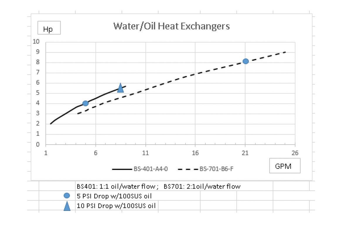
C*^ Return Line Heat ExchangerBS-401-A4-O-BR
D*^ Return Line Heat ExchangerBS-701-B6-F-BR
Water/oil: 4Hp (3KW)Rej @ 5GPM Oil Flow 1:1 Flow ratio Max oil Flow 10GPM
Includes 3/4" weld coupling for customer supplied device
Water/oil: 7Hp (5.2KW)Rej @ 15GPM Oil Flow 2:1 Flow ratio Max oil Flow 29GPM Includes 3/4" weld coupling for customer supplied device
Parker Hannifin Corporation Hydraulic Pump and Power Systems Division Marysville, Ohio USA
10
HY28-2661-CD/US V-Paks Ordering Information
Hydraulic Power Units V-Paks
Code Manapak Control Valves Function Valve Model Number NFPA Mounting Pad Nominal Flow GPM (LPM) Circuit Symbol
Code Options and Accessories Function Model Number Technical Data
E^
J
K
“DT” & “C” Series 5 PSI (0.34 bar) Cracking Pressure 25 PSI (1.72 bar) Diff. @ 15 GPM
L Bypass Check (on Heat Exch) C1220S65(65 PSI) 4.5 bar Cracking Pressure N Return Filter 40CN110B Microglass II Element, Visual 25 PSI (1.72 bar) Indicator 3 PSI (0.21 bar) Diff. @ 7 GPM (26.5
O Return Filter 12AT10C
R2
Code Directional Control Valve Model Number NFPA Mounting Pad Nominal Flow GPM (LPM) DescriptionCircuit Symbol
less
Directional Control Valve Manapak Control Valves• Options and Accessories =
PAB PT AB PT AB PT AB PT
Water valve/bulbwell 65253 + bulbwell + 3/4" weld coupling If ordered without options C or D this option will only include the 3/4" weld coupling. H Pressure Filter 15P110QXRS Microglass II Element, Vis. Ind. - 50 PSI (3.49 bar) Bypass - 4 PSI (0.27 bar), Diff. @ 7 GPM (26.5 LPM)
2" Weld coupling for customer supplied heater
Check Valve Pump Outlet
(56.8 LPM)
LPM)
12 GPM (45 LPM) Cellulose Element, Ind. Gage - 15 PSI (1.03 bar) Bypass R1 Combination Float/Temp. Switch N.O. Float Up 876782-01 Fixed Temp at 65°C (149°F) Close @ Low Level and/or 65°C (149°F) (N.O.)
Combination Float/Temp. Switch Float Up 876782-02 Fixed Temp at 65°C (149°F) Open @ Low Level and/or 65°C (149°F) (N.C.) *Heat rejection based on 40°F differential between transfer medium. ^ May require longer than standard lead time.
B D1VW001CN***D03 7 (26.5) Double (Spr. Ctr) C D1VW004CN***D03 7 (26.5) Double (Spr. Ctr) F D3W1CN** D05 20 (75.7) Double (Spr. Ctr) G D3W4CN** D05 15 (56.8) Double (Spr. Ctr) Units
valves wil be supplied with station cover plates installed.
Omit if not required
11
Parker Hannifin Corporation Hydraulic Pump and Power Systems Division Marysville, Ohio USA HY28-2661-CD/US Installation Information Hydraulic Power Units Series H, V-Packs Catalog HY28-2661-CD/US Volume Control Vertical Power Units
B A G
P T
“O” & “S3” OPTION MANIFOLD
& T
BA T
MOTOR
RETURN PORT 1/2" NPTF WITH DROP PIPE .56
HOLES - 4 PLACES PRESSURE GAGE WITH NEEDLE VALVE SYSTEM RELIEF VALVE BA Installation Information Series
Dimensions – Basic D-Pak (18.9 Liter (5 Gallon) Tank) Inch equivalents for millimeter dimensions are shown in (**) * Reference dimension consult factory if critical to application. Code MotorMotor Description Dimension KW(HP)-RPM-Frame-Phase “A” * Filter Option
(13.00) 331 (12.50) 318 (10.00) 254 .9023() 13.50343() 12.503 18 () 15.00 381 () "B" .7519.1() (1.25) 31.8 .66 16.8 () Motor Code Motor Size Dimension “B” U1, T1, T3, DG DK 56C Frame 182TC Frame 0" 19.1 (.75)
Parker Hannifin Corporation Hyd raulic Pump Division Mar yville, Ohio USA 13 263.1 (10.36) “A” * 3.1 (.12) 307.9 (12.12) 38.1 (1.5)
“M3*” & "C3*" OPTION MANIFOLD (MULTI-STATION D03 MANIFOLD) SHOWN WITH OPTION “O” RETURN FILTER SPARE RETURN PORT 1/2" NPTF WITH DROP PIPE
SPARE RETURN PORT 1/2" NPTF WITH DROP PIPE “O” & “S3” OPTION MANIFOLD (P & T BLOCK & D03 SINGLE STATION) SHOWN WITH OPTION “O” RETURN FILTER
(P
BLOCK & D03 SINGLE STATION) BASIC UNIT
TANK DRAIN SAE-12 (PLUGGED) OIL LEVEL SIGHT GAGE FILLER BREATHER “O” (“P” & “T” BLOCK) OR “S3” (“D03” SUBPLATE) SHOWN-SEE MANIFOLD OPTIONS ELECTRIC
SPARE
DIA. MOUNTING
D-Paks
Reference
HY28-2661-CD/US Catalog HY28-2661-CD/US
Vertical Power Units
Volume Control
V1 (10 Gallon Tank) Inch equivalents for millimeter dimensions are shown in (**)
355.6 (14.00) 422.4 (16.63)
–
444.5 (17.50) 422.4 (16.63)
38.1 (1.5)
T
.56 DIA. MOUNTING HOLES - 4 PLACES “O” & “S5” OPTION MANIFOLD (P & T BLOCK & D05 SINGLE STATION) BASIC UNIT
SPARE RETURN PORT 3/4" NPTF WITH DROP PIPE
ELECTRIC MOTOR
P P
“O” & “S5” OPTION MANIFOLD (P & T BLOCK & D05 SINGLE STATION) SHOWN WITH OPTION “O” RETURN FILTER
PUMP COMPENSATOR CONTROL FOR V-PAKS (NOT INCLUDED ON H-PAKS)
ROTATION ARROW
PRESSURE GAGE WITH NEEDLE VALVE
“O” (“P” & “T” BLOCK) OR “S5” (“D05” SUBPLATE) SHOWN-SEE MANIFOLD OPTIONS
FILLER BREATHER
482.6 (19.00) “B” 33.3 (1.31) P
19.1 (.75) 22.9 (.9) T
SPARE RETURN PORT 3/4" NPTF WITH DROP PIPE A-D03 B-D05 B-D03 A-D05
TANK DRAIN SAE-12 (PLUGGED)
SYSTEM RELIEF VALVE FOR H-PAKS SAFETY RELIEF VALVE FOR V-PAKS 3.1 (.12) 409.5 (16.12) &
A A B B G A-D03 B-D05
dimension consult factory if critical to application.
Parker Hannifin Corporation Hyd raulic Pump Division Mar yville, Ohio USA
Parker Hannifin Corporation Hydraulic Pump and Power Systems Division Marysville, Ohio USA
12
14
“M5*” OPTION MANIFOLD (MULTI-STATION D05 MANIFOLD) SHOWN WITH OPTION “O” RETURN FILTER
SPARE RETURN PORT 3/4" NPTF WITH DROP PIPE
B-D03 A-D05
OIL LEVEL SIGHT GAGE
“A” * 390.1 (15.36) Code KW(HP)-RPM-Frame-Phase Installation Information Series H, V-Paks Dimensions
Basic H1
Filter Option Reference * Reference
Installation Information Hydraulic Power Units Series H, V-Packs
Technical Information
Technical Information
HY28-2661-CD/US Catalog HY28-2661-CD/US Volume Control
Vertical Power Units
Series D, H, V-Paks
Manifold Options
Inch equivalents for millimeter dimensions are shown in (**).
PT X
X P
(18.9 LITER (5
Hydraulic Power Units Series D, H, V-Packs
PT X
52.3 (2.06)
RETURN PORT SAE-10 RETURN PORT SAE-10 “A” PORT SAE-8 “B” PORT SAE-8
A B D03 MNTG SURFACE
P T
T BA
P
47.8 (1.88) 22.0 (.87)
SUPPLY PORT SAE-12 P PUMP SUPPLY
PT X X
X
T
RETURN PORT SAE-12 RETURN PORT SAE-12 RETURN PORT SAE-12
A B
D05 COVER PLATE
X
“A” PORT SAE-10 “B” PORT SAE-10
T
44.5 (1.75) P
53.8 (2.12)
BA 85.9 (3.38) 104.6 (4.12)
SUPPLY PORT SAE-12 PUMP SUPPLY
PT X X X RETURN PORT SAE-12 X
A B D05 MNTG SURFACE
T 31.8 (1.25) 31.8 (1.25)
87.4 (3.44) 44.2 (1.75) 44.5 (1.75) 44.5 (1.75)
RETURN PORT SAE-12 RETURN PORT SAE-12 “A” PORT SAE-10 “B” PORT SAE-10 S5
P T
38.1 (1.50) 17.5 (.69) 53.8 (2.12)
SUBPLATE OPTION FOR USE WITH D3W VALVE (NFPA D05)
Parker Hannifin Corporation Hydraulic Pump Division Maryville, Ohio USA
Parker Hannifin Corporation Hydraulic Pump and Power Systems Division Marysville, Ohio USA
14
16 A-D03 B-D05 B-D03 A-D05
A-D03
PT X X
B-D05 B-D03 A-D05 SUPPLY PORT SAE-10 P PUMP SUPPLY T A B RETURN PORT SAE-10 RETURN PORT SAE-10 D03 COVER PLATE “A” PORT SAE-8 “B” PORT SAE-8
O MANIFOLD OPTION FOR SUPPLY & RETURN CONNECTIONS
GAL.) RESERVOIR UNITS) O MANIFOLD OPTION
SUPPLY & RETURN CONNECTIONS
SUPPLY PORT SAE-10 PUMP SUPPLY RESERVOIR
FOR
(37.9, 75.7, 113.6, 115.4 LIT (10, 20, 30, 40 GAL)
UNITS)
S3 SUBPLATE OPTION FOR USE WITH D1VW VALVE (NFPA D03)
X
Technical Information
Technical Information Series D, H, V-Paks
HY28-2661-CD/US Catalog HY28-2661-CD/US Volume Control Vertical Power Units
Manifold Options
Inch equivalents for millimeter dimensions are shown in (**).
Option M33/M35
Option M53/M55
Parker Hannifin Corporation
Hydraulic Pump and Power Systems Division Marysville, Ohio USA
Hydraulic Power Units
Series D, H, V-Packs
PUMP SUPPLY
RETURN PORT SAE-10 D03 MNTG SURFACE
54.0 (2.12) PER STATION 4.25
A B
T A B G "G" SAE-6 A B
3 AND 5 STATION AVAIL.
"A"&"B"PORTS SAE-8 3 AND 5 STATIONS) X PT A B
33.3 (1.31) 22.1 (0.87) 44.5 (1.75)
M33 AND M35
G
3 AND 5 STATION MANIFOLD OPTIONS FOR USE WITH NFPA D03 VALVES
1.06
PUMP SUPPLY
RETURN PORT SAE-12 D05 MNTG SURFACE
A B
T A B G "G" SAE-6
82.6 (3.25) PER STATION 3 AND 5 STATION AVAIL.
"A"&"B"PORTS SAE-8 3 AND 5 STATIONS
P
B G
X PT A A B
54.0 (2.12) 31.8 (1.25) 17.5 (0.69) 54.0 (2.12)
82.6 (3.25) 165.1 (6.50)
M53 AND M55
3 AND 5 STATION MANIFOLD OPTIONS FOR USE WITH NFPA D05 VALVES
39.6 (1.56)
Parker Hannifin Corporation Hydraulic Pump Division Maryville, Ohio USA
15
17
noitamrofnI
HY28-2661-CD/US Catalog HY28-2661-CD/US
Technical Information
Vertical Power Units
Volume Control
skaP-V seireS
Pressure Control Option "B"–Unloading Valve
Hydraulic Power Units Series D, H, V-Packs
"H"PAK WITH "S3" MANIFOLD 3.4-19.3 LPM (0.9-5.1 GPM) FLOW RATES ONLY (CONNECTED TO SYSTEM RETURN LINE)
"H"PAK WITH "M3*" MANIFOLD 3.4-19.3 LPM (0.9-5.1 GPM) FLOW RATES ONLY (CONNECTED TO SYSTEM RETURN LINE)
"H"PAK WITH "OMIT","S5","S6","M5*","M6*" MANIFOLDS 3.4-19.3 LPM (0.9-5.1 GPM) FLOW RATES ONLY (PLUMBED DIRECTLY BACK TO TANK)
"H"PAK WITH "OMIT","S3","S5","S6","M3*","M5*","M6*" MANIFOLDS 23.84-46.56 LPM (6.3-12.3 GPM) FLOW RATES ONLY (PLUMBED DIRECTLY BACK TO TANK)
Parker Hannifin Corporation Hydraulic Pump Division Mar yville, Ohio USA
Parker Hannifin Corporation Hydraulic Pump and Power Systems Division Marysville, Ohio USA
16
18
UPRIGHT INVERTED A T B B A G P AB T INVERTED UPRIGHT
B-D03 A-D05 B-D05 A-D03
B-D05 A-D03 A-D05 B-D03
HY28-2661-CD/US Catalog HY28-2661-CD/US
noitamrofnI
skaP-V seireS
Volume Control Vertical Power Units
Hydraulic Power Units Series D, H, V-Packs
Pressure Control Option "B"–Unloading Valve
Pressure Control Option "B"– Unloading Valve
"D"PAK WITH "S3" MANIFOLD (CONNECTED TO SYSTEM RETURN
"H"PAK WITH "S3" MANIFOLD 3.4-19.3 LPM (0.9-5.1 GPM) FLOW RATES ONLY (CONNECTED TO SYSTEM RETURN LINE)
"D"PAK WITH "M3*" MANIFOLD (CONNECTED TO SYSTEM RETURN
"H"PAK WITH "M3*" MANIFOLD 3.4-19.3 LPM (0.9-5.1 GPM) FLOW RATES ONLY (CONNECTED TO SYSTEM RETURN LINE)
"H"PAK WITH "OMIT","S5","S6","M5*","M6*" MANIFOLDS 3.4-19.3 LPM (0.9-5.1 GPM) FLOW RATES ONLY (PLUMBED DIRECTLY BACK TO TANK)
"D"PAK WITH "OMIT" MANIFOLD (CONNECTED TO SYSTEM RETURN
"H"PAK WITH "OMIT","S3","S5","S6","M3*","M5*","M6*" MANIFOLDS 23.84-46.56 LPM (6.3-12.3 GPM) FLOW RATES ONLY (PLUMBED DIRECTLY BACK TO TANK)
Parker Hannifin Corporation Hydraulic Pump and Power Systems Division Marysville, Ohio USA
17
Parker Hannifin Corporation Hydraulic Pump Division Mar yville, Ohio USA
18
UPRIGHT INVERTED A T B B A G P AB T INVERTED
UPRIGHT
B-D03 A-D05 B-D05 A-D03
B-D05 A-D03 A-D05 B-D03 Ohio skaP-V
noitamrofnI P T BA T B A B A G INVERTED UPRIGHT INVERTED UPRIGHT P T BA INVERTED UPRIGHT
seireS
Technical Information
18
20 Technical Information
V-Pak – Compensator Options HI LO HI SOL LO SOL “OMIT” OPTION SINGLE PRESSURE REMOTE COMPENSATOR “B” OPTION SINGLE PRESSURE REMOTE COMPENSATOR W/LOW PRESS. STANDBY “D” OPTION BI-PRESSURE REMOTE COMPENSATOR W/LOW PRESS. STANDBY “C” OPTION BI-PRESSURE REMOTE COMPENSATOR PUMP COMPENSATOR CONTROL ADJUSTMENT PUMP COMPENSATOR CONTROL ADJUSTMENT
ENERGIZE TO BUILD PRESSURE LOW PSI T LOW SOL STANDBY HIGH PSI HIGH SOL P P T SOLENOID IS
WITH
AND
SAE -6 AUX. VENT PORT (SAE-6)
HI LO HI SOL LO SOL PUMP
HIGH PRESS. CONTROL PUMP
LOW PRESS. CONTROL
ENERGIZE FOR HIGH PRESSURE HI LO HI SOL LO SOL HIGH PRESS. SOLENOID
ENERGIZE FOR HIGH PRESSURE P T PUMP COMPENSATOR PRESSURE (INLET) PORT PUMP COMPENSATOR TANK (RETURN) PORT SAE-6 37 FLARE “P” & “T” PORTS ATTACH POINTS FOR CUSTOMER SUPPLIED REMOTE COMPENSATOR PUMP COMPENSATOR HIGH PRESSURE CONTROL PUMP COMPENSATOR LOW PRESSURE CONTROL P LOW PSI T HIGH PSI HIGH SOL SOLENOID IS LOW WATT WITH DIN. 43650 CONNECTOR AND MANUAL OVERRIDE P LOW PSI T HIGH PSI HIGH SOL LOW SOL STANDBY SOLENOID IS LOW WATT WITH DIN. 43650 CONNECTOR AND MANUAL OVERRIDE P “F” OPTION PROVISION FOR CUSTOMER SUPPLIED REMOTE COMPENSATOR SAE -6 37 FLARE P PT T Technical Information
Parker Hannifin Corporation Hydraulic Pump and Power Systems Division Marysville, Ohio USA HY28-2661-CD/US Catalog HY28-2661-CD/US Volume Control Vertical Power Units Parker Hannifin Corporation Hydraulic Pump Division Maryville, Ohio USA
Series V-Paks
LOW PRESS. STANDBY (N.O.)
LOW WATT
DIN. 43650 CONNECTOR
MANUAL OVERRIDE
LOW PRESS. STANDBY (N.O.) ENERGIZE FOR LOW PRESSURE
COMPENSATOR
COMPENSATOR
HIGH PRESS. SOLENOID (N.O.)
(N.O.)
Hydraulic Power Units Series V-Packs
ACCESSORY OPTIONS—D&H PAKS
RETURN LINE AIR/OIL HEAT EXCHANGER (B1 OR B2) WATER/OIL HEAT EXCHANGER SYSTEM COOLING/FILTER LOOP PRESSURE FILTER WELD COUPLING FOR HEATER CHECK VALVE–PUMP OUTLET
CHECK VALVE–RETURN LINE BYPASS RETURN LINE FILTER RETURN LINE FILTER COMBINATION TEMP/LEVEL SWITCH
ACCESSORY OPTIONS—V PAKS PUMP CASE HEAT EXCHANGER RETURN LINE AIR/OIL HEAT EXCHANGER (B1 OR B2) WATER/OIL HEAT EXCHANGER WATER/OIL HEAT EXCHANGER WATER CONTROL VALVE PRESSURE FILTER WELD COUPLING FOR HEATER
CHECK VALVE–PUMP OUTLET CHECK VALVE–RETURN LINE BYPASS RETURN LINE FILTER RETURN LINE FILTER COMB. TEMP/LEVEL SWITCH (R1 OR R2)
19
Parker Hannifin Corporation Hydraulic Pump and Power Systems Division Marysville, Ohio USA HY28-2661-CD/US Technical Information Hydraulic Power Units Series V-Packs
A B C D E H J
OPTION OPTION OPTION OPTION OPTION OPTION OPTION
K L
N O R OPTION OPTION OPTION OPTION OPTION
B C E H J
OPTION OPTION OPTION OPTION OPTION OPTION
K
(R1 OR R2) L N O R OPTION OPTION OPTION OPTION SEE MANIFOLD OPTIONS SEE MANIFOLD OPTIONS SEE COMPENSATOR OPTIONS SAE - 10 SAE - 6 SAE - 10 1/2" NPT - “D” PAKS 3/5" NPT - “H” PAKS SAE - 10 SAE - 6 SAE - 10 SAE - 12 SAE - 12 CONNECTED TO RETURN LINE WITH OPTION “B1” & “B2” SEE MANIFOLD OPTIONS SEE MANIFOLD OPTIONS SEE COMPENSATOR OPTIONS SAE - 10 SAE - 6 SAE - 10 1/2" NPT - “D” PAKS 3/5" NPT - “H” PAKS SAE - 10 SAE - 6 SAE - 10 SAE - 12 SAE - 12 CONNECTED TO RETURN LINE WITH OPTION “B1” & “B2”
HY28-2661-CD/US Catalog HY28-2661-CD/US
Technical Information
Technical Information Series D-Paks
Volume Control Vertical Power Units
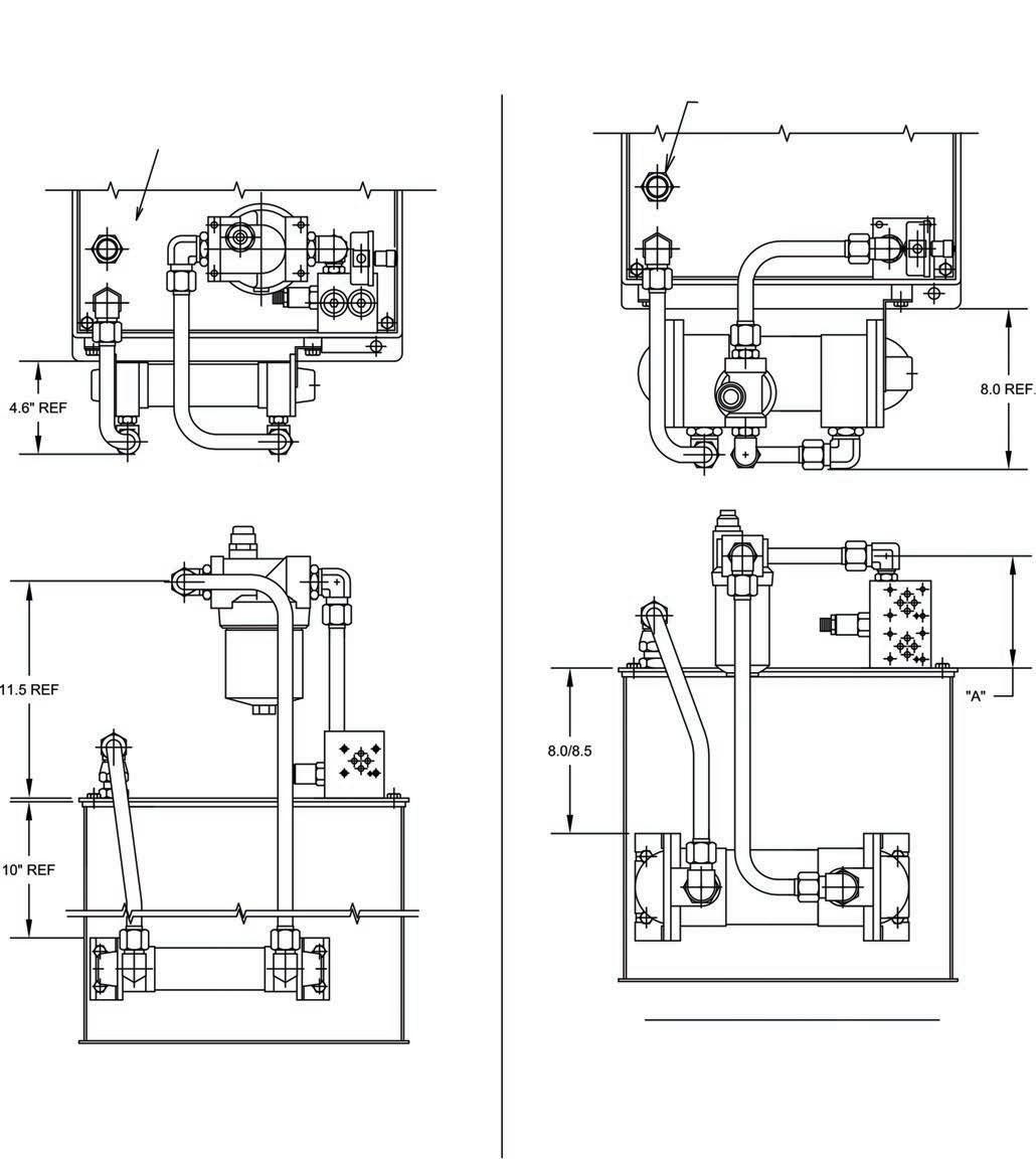
Dimensions – D-Pak (5 Gallon Tank) Accessories
Hydraulic Power Units Series D-Packs
Inch equivalents for millimeter dimensions are shown in (**). Installation information is for reference only. Consult factory or visit Parker's Econfigurator for detailed information.
SPARE RETURN PORT 1/2" NPTF WITH DROP PIPE (NOT SHOWN)
19.8 [0.78] 10.8 [0.43] 129.5 [5.1] REF.
OPTION "B1" AIR/OIL HEAT EXCHANGER
16.3 [0.64]
DIM "A" REF
OPTION "N" OR "O" RETURN FILTER
OPTION "R1" OR "R2" FLOAT/TEMP. SWITCH (1/2" ELEC. CONN.)
OPTION "H" PRESSURE FILTER
Parker Hannifin Corporation Hydraulic Pump and Power Systems Division Marysville, Ohio USA
Parker Hannifin Corporation Hydraulic Pump Division Mar yville, Ohio USA
20
22
BA P T
HY28-2661-CD/US
Catalog HY28-2661-CD/US
Technical Information
Vertical Power Units
Hydraulic Power Units Series H, V-Packs Catalog HY28-2661-CD/US
Technical Information Series H, V-Paks
Volume Control Vertical Power Units
Volume Control
Technical Information Series H, V-Paks
Dimensions – H1& V1 (10 Gallon Tank)
Accessories
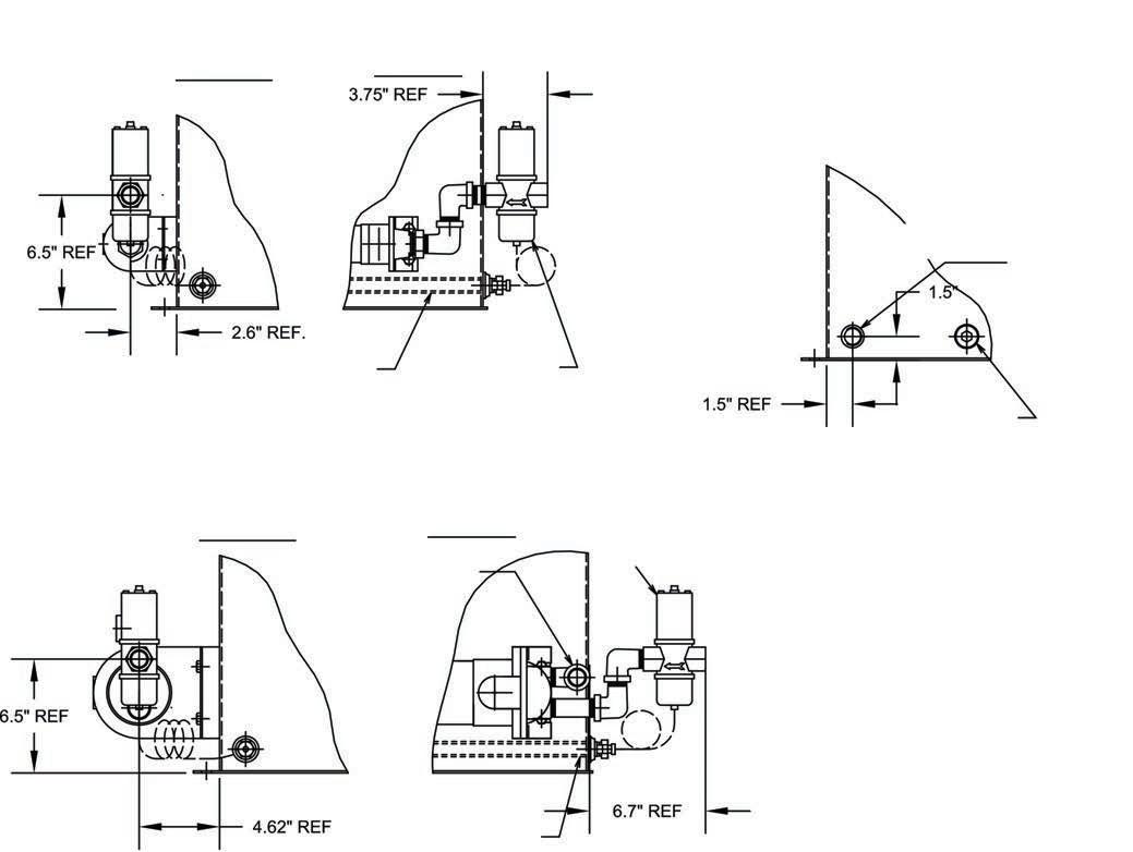
Dimensions – H1& V1 (10 Gallon Tank) Accessories
Inch equivalents for millimeter dimensions are shown in (**). Installation information is for reference only, consult factory or visit Parker's Econfigurator for detailed information
SPARE RETURN PORT 3/4" NPTF WITH DROP PIPE
OPTION "M", "N", "O" OR "V" RETURN FILTER
OPTION "B1" AIR/OIL
HEAT EXCHANGER
16.9 [0.67] 10.2 [0.40] 130 [5.1] 26.5 [1.04]
16.9 [0.67] 10.2 [0.40] 130 [5.1] 26.5 [1.04]
DIM "A" REF
DIM "A" REF
OPTION "R1" OR" R2" FLOAT/TEMP. SWITCH (1/2" ELEC. CONN.)
OPTION "H" PRESSURE FILTER
OPTION "R1" OR" R2" FLOAT/TEMP. SWITCH (1/2" ELEC. CONN.)
OPTION "H" PRESSURE FILTER
12.7 [0.50]
12.7 [0.50]
Inch equivalents for millimeter dimensions are shown in (**). Installation information is for reference only, consult factory or visit Parker's Econfigurator for detailed information P
OPTION "A" PUMP CASE HEAT EXCHANGER (USED ON "V" PAKS ONLY)
OPTION "A" PUMP CASE HEAT EXCHANGER (USED ON "V" PAKS ONLY)
89.7 [3.53]
89.7 [3.53]
DIM "A" REF
DIM "A" REF
Parker Hannifin Corporation
Hydraulic Pump and Power Systems Division Marysville, Ohio USA
FLOAT 2" BELOW LOW LEVEL
FLOAT 2" BELOW LOW LEVEL
Parker Hannifin Corporation
Hydraulic Pump Division Mar yville, Ohio USA
21
23
T P T A-D03 B-D05 B-D03 A-D05 A-D03 B-D05 B-D03 A-D05
OPTION "B1" AIR/OIL OPTION "M", "N", "O" OR "V" RETURN FILTER SPARE RETURN PORT 3/4" NPTF WITH DROP PIPE
HEAT EXCHANGER
23
Parker Hannifin Corporation Hydraulic Pump Division Mar yville, Ohio USA
P T P T A-D03 B-D05 B-D03 A-D05 A-D03 B-D05 B-D03 A-D05
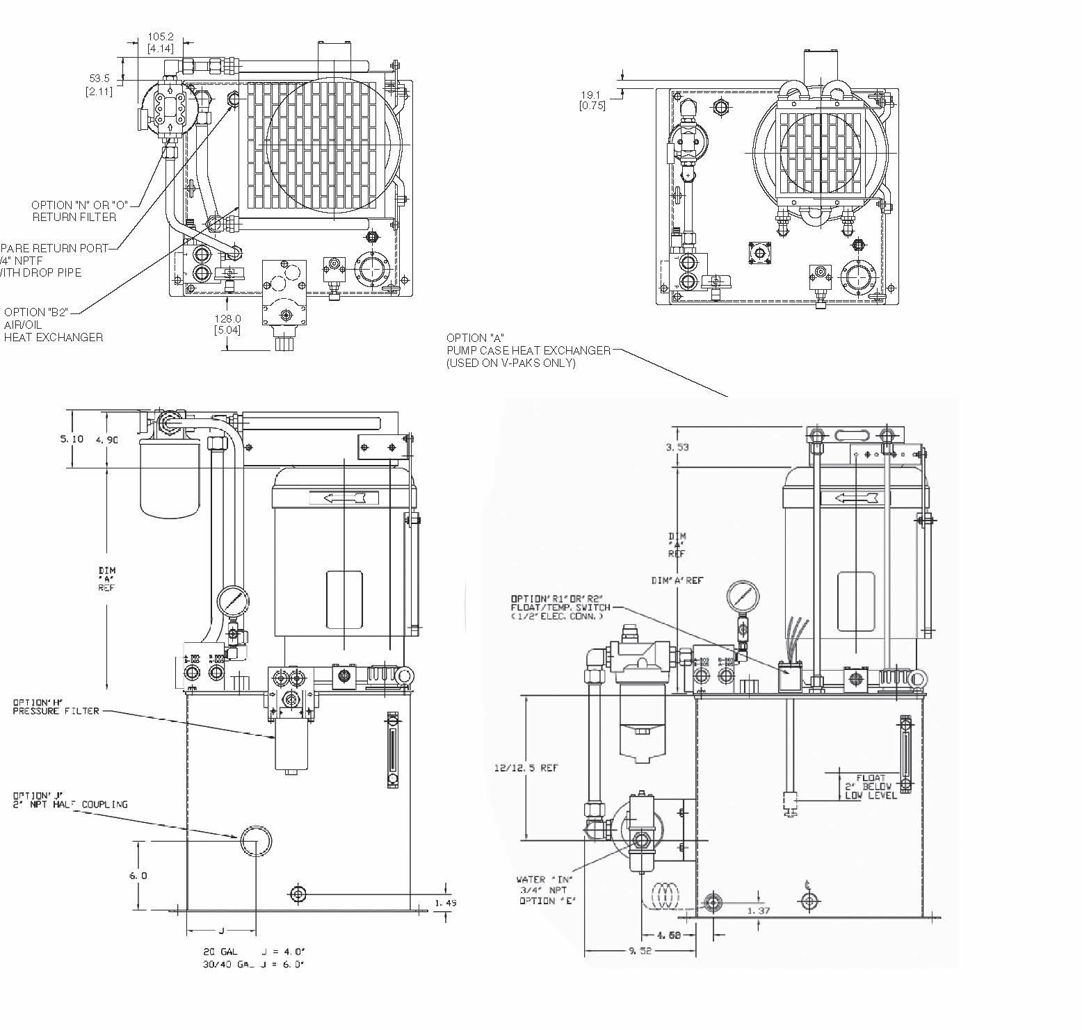
22 Parker Hannifin Corporation Hydraulic Pump and Power Systems Division Marysville, Ohio USA HY28-2661-CD/US Hydraulic Power Units Series H, V-Packs Dimensions – H1 & V1 (10 Gallon tank) Accessories (continued)
RETURN PORT 3/4" NPTF WITH DROP TUBE (REF.)
USE FOR REFERENCE ONLY EXACT DIMENSIONS MAY VARY DEPENDING ON COMBINATION OF OTHER OPTIONS
RETURN PORT 3/4" NPTF WITH DROP TUBE (REF.) H1 /V1 WITH S3 MANIFOLD OPTION “C” WATER/OIL HEAT EXCHANGER OPTION “N” 40 CN RETURN FILTER H1 /V1 WITH M3* MANIFOLD OPTION “D” WATER/OIL HEAT EXCHANGER OPTION “M” 15 CN / OPTION “O” 12AT RETURN FILTER (M32 W /15CN SHOWN) MANIFOLD M33 M35 DIMENSION “A” 7.6 REF. 11.8 REF. Technical Information
SPARE
NOTE:
SPARE
23
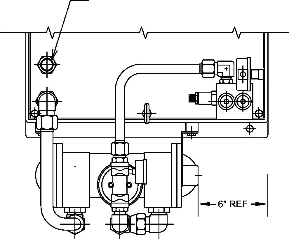
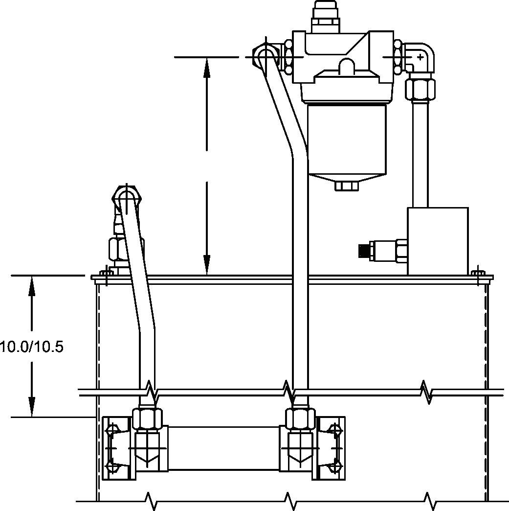
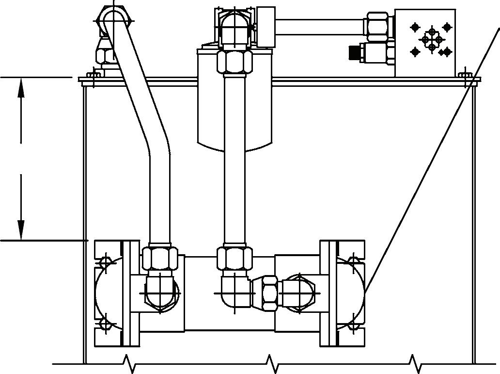
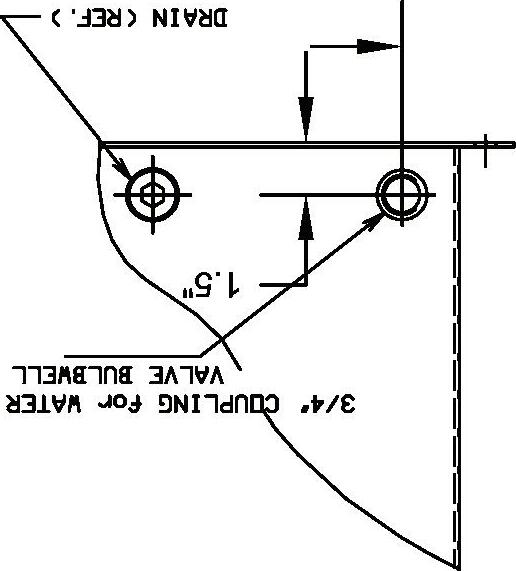
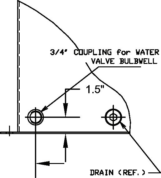
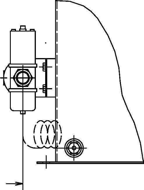
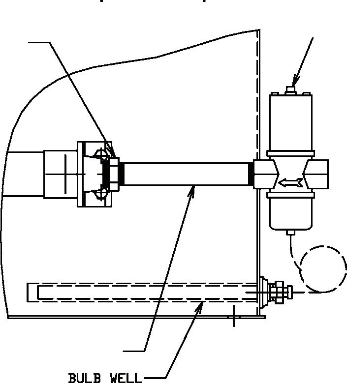
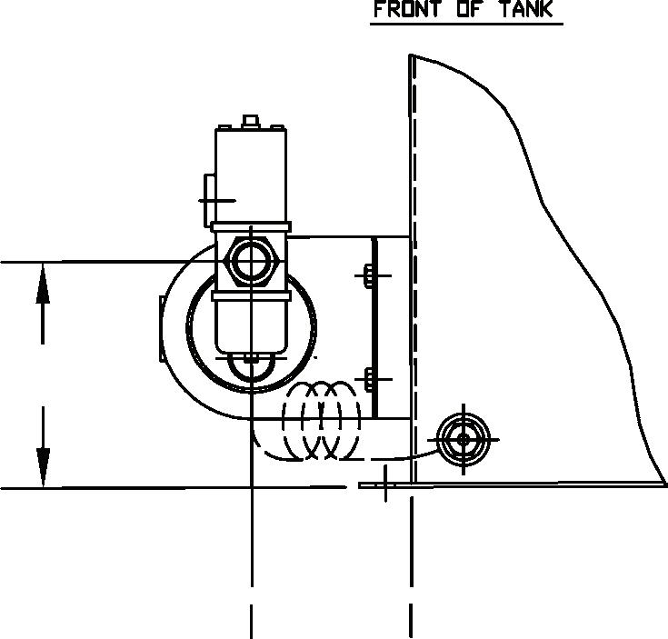
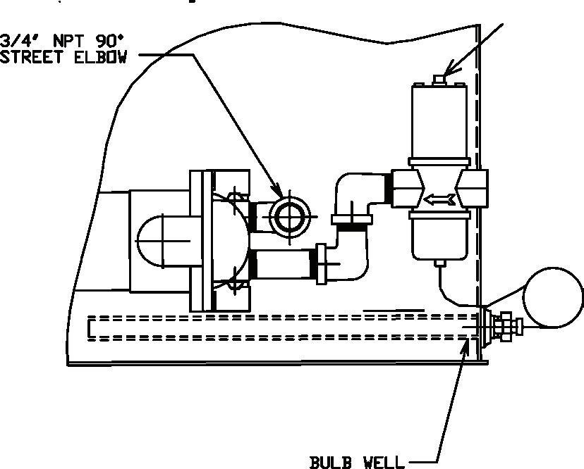
HY28-2661-CD/US Hydraulic Power Units Series H, V-Packs Dimensions – H1 & V1 (10 Gallon tank) Accessories (continued) FRONT OF TANK FRONT OF TANK SIDE OF TANK SIDE OF TANK BULB WELL BULB WELL WATER MODULATING VALVE DRAIN (REF.) WATER MODULATING VALVE 3/4" COUPLING FOR WATER VALVE BULBWELL 3/4" NPT 90º STREET ELBOW OPTION “E” WATER MODULATING VALVE WITH “C” HEAT EXCHANGER & 10 GALLON TANK OPTION “E” WATER MODULATING VALVE WITH “D” HEAT EXCHANGER & 10 GALLON TANK IF OPTION “E” ORDERED WITH NO HEAT EXCHANGER THE UNIT WILL BE SUPPLIED WITH 3/4" WELD COUPLING ONLY. Technical Information
Parker Hannifin Corporation
Hydraulic Pump and Power Systems Division Marysville, Ohio USA
HY28-2661-CD/US Technical Information
Dimensions – H2, 3, 4 & V2, 3, 4 (20, 30,40 Gallon Tank)
Hydraulic Power Units Series H, V-Packs
Accessories
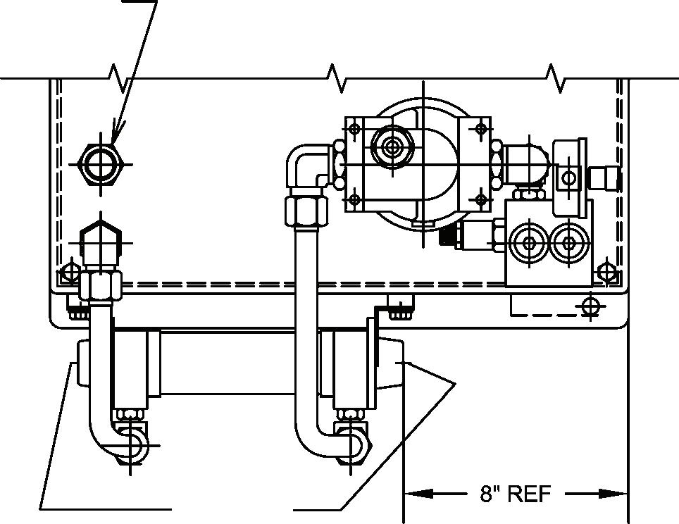
Inch equivalents for millimeter dimensions are shown in (**) Installation information is for reference only. Consult factory or visit Parker's Econfigurator for detailed information.
24
Parker Hannifin Corporation Hydraulic Pump and Power Systems Division Marysville, Ohio USA
25
3, 4 & V2, 3, 4
30,
millimeter
PORT 3/4"
Parker Hannifin Corporation Hydraulic Pump and Power Systems
Division
Marysville, Ohio USA HY28-2661-CD/US Technical Information Hydraulic Power Units Series H, V-Packs Dimensions – H2,
(20,
40 Gallon Tank) Accessories (CONT) Inch equivalents for
dimensions are shown in (**) Installation information is for reference only Consult factory or visit Parker's Econfigurator for detailed information SPARE RETURN
NPTF WITH DROP TUBE (REF.)
H / V 2,3,4 WITH S3 MANIFOLD OPTION “C” WATER/OIL HEAT EXCHANGER OPTION “N” 40CN RETURN FILTER H / V 2,3,4 WITH S3 MANIFOLD OPTION “D” WATER/OIL HEAT EXCHANGER OPTION “O” 12AT / OPTION “M” 15CN FILTER (12AT FILTER SHOWN)
NOTE: USE FDR REFERENCE ONLY. EXACT DIMENSIONS MAY VARY DEPENDING ON COMBINATION OF OTHER OPTIONS. SPARE RETURN PORT 3/4" NPTF WITH DROP TUBE (REF.)
HY28-2661-CD/US Catalog HY28-2661-CD/US VolumeControl VerticalPowerUnits
HY28-2661-CD/US Technical Information
Hydraulic Power Units Series H, V-Packs
Parker Hannifin Corporation Hydraulic Pump and Power Systems Division Marysville, Ohio USA
26
21
Parker Hannifin Corporation HydraulicPumpDivision Maryville,OhioUSA 24 Technical Information Series H,V-Paks Dimensions –H2, 3, 4 & V2, 3, 4 Accessories (CONT) Technical Information
WATER
WATER
1"-3/4"
2.65 REF 1.5" REF DRAIN
3/4" COUPLING FOR WATER VALVE BULBWELL 3/4" NPT NIPPLE, 7" LONG BULB
BULB
4.62" REF 6.5" REF 3/4" NPT 90
Hydraulic Power Units Series H, V-Packs Inch equivalents for millimeter dimensions are shown in (**). Installation information is for reference only. Consult factory or visit Parker's Econfigurator for detailed information. SIDE OF TANK SIDE OF TANK FRONT OF TANK
MODULATING VALVE
MODULATING VALVE
NPT REDUCER
(REF.)
WELL FRONT OF TANK OPTION “E” WATER MODULATING VALVE WITH “C” HEAT EXCHANGER & 20/30/40 GALLON TANK (20 GALLON TANK SHOWN) OPTION “E” WATER MODULATING VALVE WITH “D” HEAT EXCHANGER & 20/30/40 GALLON TANK IF OPTION “E” ORDERED WITH NO HEAT EXCHANGER THE UNIT WILL BE SUPPLIED WITH 3/4" WELD COUPLING ONLY.
WELL
STREET ELBOW
HY28-2661-CD/US
Technical Information
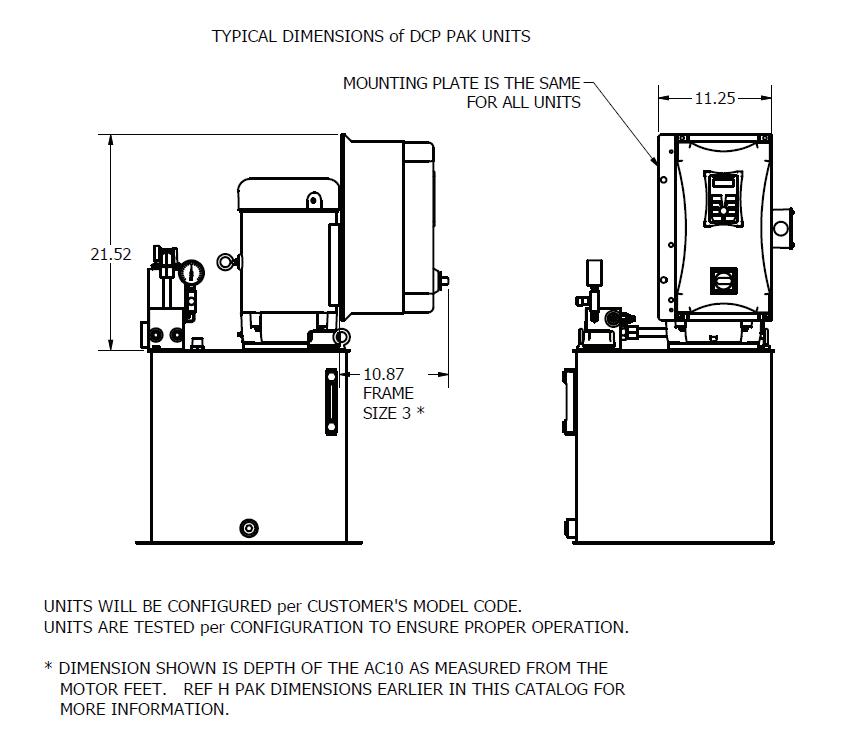
DCP PAK DIMENSIONS
Hydraulic Power Units H-Pak with
DCP
UNITS WILL BE CONFIGURED PER CUSTOMER’S MODEL CODE. UNITS ARE TESTED PER CONFIGURATION TO ENSURE PROPER OPERATION.
*DIMENSION SHOWN IS DEPTH OF THE AC10 AS MEASURED FROM THE MOTOR FEET. REF H PAK DIMENSIONS EARLIER IN THE CATALOG FOR MORE INFORMATION.
27
Parker Hannifin Corporation Hydraulic Pump and Power Systems Division Marysville, Ohio USA
HY28-2661-CD/US Catalog HY28-2661-CD/US Volume Control Vertical Power Units
Technical Information Series D,H,V-Paks
Performance Data – Maximum Working Pressures
Hydraulic Power Units Series D, H, V-Packs
Hydraulic Power Units Series D, H, V-Packs
Represents maximum operating pressure with pump/motor combination. This will be the maximum relief valve or compensator setting **** Represents maximum operating pressure with pump/motor combination. When used on power unit products, the highest relief valve or compensator setting will be 3000 PSI.
D & H Pak - Pump/Motor Combinations Maximum Operating Pressure Bar (PSI)
Pump Code Motor KW (HP) Flow at.37 (.5) .60 (.75).75 (1)1.1 (1.5)1.5 (2)2.2 (3)3.7 (5)5.6 (7.5)7.5 (10)11.2 (15)14.9 (20) 1725 RPM Max Operating Pressure (Theoretical) LPM (GPM) 3.4 (0.9) 55.8(810)84.1(1220) 111 7(1620) 167.5(2430) 22 3 .4( 3 240 ) 3 .4( 240 22 3 3 240 3 240 4.9 (1.3) 40.0(580)60.0(870) 80 0(1160) 119.3(1730)159 3(2310) 23 9 .2( 3 470 ) .2( ) 23 9 .2( 3 470 ) .2( ) .2( 6.8 (1.8) 29.6(430) 44.1(640) 59 3(860) 88 3(1280) 118 6(1720)177.2(2570) 27 5 .0( 3 988 ) 5 .0( 988 .0( ) .0( 8.7 (2.3) 22.8(330) 34.5(500) 46 2(670) 69 0(1000)92.4(1340)138.6(2010) 23 1 .0( 3 350 ) 1 .0( 350 23 .0( 3 350 ) .0( 350 10.2 (2.7) 20.0(290) 30.3(440)40.0(580)60.0(870)80.7(1170) 120.7(1750) 201 3(2920) 12.1 (3.2) 15.9(230) 24.1(350)31.7(460)48.3(700)64.1(930) 96.5(1400) 160.6(2330) 24 1 .3( 3 500 ) .3( ) .3( 17.0 (4.5) 11.0(160) 17.2(250)22.8(330)33.8(490)45.5(660) 69.0(1000) 115.1(1670) 172.4(2500) 22 8 .9( 3 320 ) .9( 3 ) ) 19.3 (5.1) 10.3(150) 15.2(220) 20 7(300) 30.3(440)40.7(590) 61.4(890) 102 0(1480) 153.1(2220) 204.1(2960) 27 5 .0( 3 988 ) 5 .0( 988 ) 23.8 (6.3) 8.3(120)12.4(180)16.5(240)24.8(360)33.1(480) 49.6(720) 82 7(1200) 124.1(1800) 165 5(2400) 24 8 .2( 3 600 ) 8 .2( 600 ) 30.7 (8.1) 9.7(140)12.4(180) 18 6(270)24.8(360) 37 2(540) 62 7(910)93.8(1360) 125.5(1820) 187 5(2720) 25 1 .0( 3 640 ) .0( ) 35.6 (9.4) 8.3(120)11.0(160) 16 5(240)21.4(310) 32 4(470) 53 8(780)81.4(1180) 108.2(1570) 162 0(2350) 21 5 .8( 3 130 ) .8( ) 46.6 (12.3) 8.3(120) 11.7(170) 15 9(230) 24 1(350)40.0(580) 60.0(870) 80.0(1160) 120.0(1740) 160.0(2320)
V-Pak - Pump/Motor Combinations Maximum Operating Pressure Bar (PSI)
Motor KW (HP)
PumpLPM (GPM) @ 1725 RPM1.5 (2)2.2 (3)3.7 (5)5.6 (7.5)7.5 (10)11.2 (15)14.9 (20) PVP16 7.6 (2.0) 72.4(1050)108.2(1570) 179.3(2600) 266 .1( 386 0) 266 .1( 3860 ) 266 .1( 386 0) 266 .1( 3860 )
PVP16 9.5 (2.5) 64.1(930) 94.5(1370)155.1(2250) 232 .4( 3370 ) 232 .4( 337 0) .4( ) .4( 0) 0) PVP16 11.4 (3.0) 57.2(830)84.8(1230) 137.9(2000)206.8(3000) PVP16 13.2 (3.5) 51.7(750)75.8(1100) 124.1(1800)184.8(2680) 246 .1( 3570 ) 357 0) .1( ) 0) PVP16 15.1 (4.0) 46.9(680)68.9(1000) 113.8(1650)168.2(2440) 223 .4( 3240 ) 324 0)
PVP16 17.0 (4.5) 43.4(630)63.4(920)103.4(1500)153.8(2230)204.8(2970) 305 .4( 443 0) 305 .4( 4430 ) .4( PVP16 18.9 (5.0) 40.0(580)58.6(850) 96.5(1400) 142.0(2060)188 9(2740) 281 .3( 408 0) 281 .3( 4080 ) .3( PVP16 20.8 (5.5) 37.9(550)55.2(800) 89.6(1300) 132.4(1920)175 1(2540) 261 .3( 379 0) 261 .3( 3790 ) 261 379 261 3790 .3( PVP16 22.7 (6.0) 35.2(510)51.7(750) 83.4(1210) 123.4(1790)163 4(2370) 244 .1( 354 0) 244 .1( 3540 ) .1( 354 0) .1( 3540 ) .1( PVP16 24.6 (6.5) 33.1(480)48.3(700) 77.9(1130) 115.8(1680)153 0(2220) 228 .2( 331 0) 228 .2( 3310 ) 228 331 228 3310 .2( PVP16 26.5 (7.0) 31.0(450)45.5(660) 73.8(1070) 108.9(1580)144 8(2100) 215 .1( 312 0) 215 .1( 3120 ) 215 .1( 312 0) 215 .1( 3120 ) .1( PVP33 30.3 (8.0) 66.2(960) 97.9(1420)129.6(1880)193 1(2800) 255 .1( 370 0) 255 .1( 3700 ) .1( 0) .1( ) PVP33 32.2 (8.5) 64.1(930) 93.1(1350)123.4(1790)182 7(2650) 242 .7( 352 0) 242 .7( 3520 ) PVP33 34.1 (9.0) 60.7(880) 88.9(1290)117.2(1700)174 4(2530) 231 .0( 335 0) 231 .0( 3350 ) 231 .0( 335 0) 231 .0( 3350 ) PVP33 36.0 (9.5) 57.9(840) 84.8(1230)112.4(1630)166 2(2410) 220 .6( 320 0) 220 .6( 3200 ) .6( 0) .6( )
PVP33 37.9 (10.0) 55.2(800) 81.4(1180)106.9(1550)159 3(2310) 206.8(3000)
PVP33 39.7 (10.5) 53.1(770) 77.9(1130)102.7(1490)152 4(2210) 202.7(2940)
PVP33 41.6 (11.0) 51.0(740) 75.2(1090)98.6(1430) 146.9(2130) 194.4(2820)
PVP33 43.5 (11.5) 49.0(710) 72.4(1050)95.1(1380) 141.3(2050) 186.8(2710)
PVP33 45.4 (12.0) 47.6(690) 69.6(1010)91.7(1330) 135.8(1970) 180.0(2610)
PVP33 47.3 (12.5) 46.2(670) 66.9(970)88.3(1280) 131.0(1900)173.7(2520)
PVP33 49.2 (13.0) 44.8(650) 64.8(940)85.5(1240) 126.9(1840)167.5(2430)
PVP33 51.1 (13.5) 43.4(630) 62.7(910)82.7(1200) 122.7(1780)162.0(2350)
PVP33 53.0 (14.0) 42.1(610) 60.7(880)80.0(1160) 118.6(1720)157.2(2280)
PVP33 54.9 (14.5) 40.7(590) 59.3(860)77.9(1130) 115.1(1670)152.4(2210)
PVP33 56.8 (15.0) 39.3(570) 57.2(830)75.2(1090) 111.7(1620)147.5(2140)
25
HY28-2661-CD/US 22
Parker Hannifin Corporation HydraulicPumpDivision Maryville, Ohio USA
Parker Hannifin Cor poration Hydraulic Pump Division Marysville, Ohio USA
28 Parker Hannifin Corporation Hydraulic Pump and Power Systems Division Marysville, Ohio USA
Technical Information
****
Information
28
HY28-2661-CD/US Catalog HY28-2661-CD/US
Volumetric Efficiency
Overall Efficiency Flow
Vertical Power Units
Volume Control
Standard
Pumps
Volumetric
Compensated Power
NOTE: The efficiencies and data in the graph are good only for pumps running at 1800 RPM and stroked to maximum. To calculate approximate horsepower for the other conditions, use the following formula:
Actual GPM is directly proportional to drive speed and maximum volume setting. Flow loss, however, is a function of pressure only.
WHERE: Q =Actual Output Flow in GPM PSI =Pressure At Pump Outlet CHp =Input Horsepower @ Full compensation @ 1800 RPM (from graph read at operating pressure) N = Drive Speed in RPM
Parker Hannifin Corporation
Hydraulic Pump and Power Systems Division Marysville, Ohio USA
(2200) 206.8 (3000) 206.8 (3000)
Parker Hannifin Corporation
Pump Division
USA
29
Hydraulic
Maryville, Ohio
26 8 10 12 14 16 18 20 100 90 80 70 60 50 Flow Efficiency% Power PVP33 @ 1800 RPM 0 4 2 6 30.3 37.9 45.4 53.0 60.6 68.2 75.7 0 15.1 7.6 22.7 0 0 Bar PSI 69 1000 138 2000 207 3000 275 4000 Pressure GPM LPM 0 6.0 11.9 17.9 23.9 29.8 0 8.0 16.0 24.0 32.0 40.0 HPKW
Efficiency Overall Efficiency Flow InputPoweratFullFlow Compensated Power 4 5 6 7 8 9 10 100 90 80 70 60 Flow Efficiency% Power PVP16 @ 1800 RPM 0 2 1 3 15.1 18.9 22.7 26.5 30.3 34.1 37.9 0 7.6 3.8 11.4 0 0 Bar PSI 69 1000 138 2000 207 3000 275 4000 Pressure GPM LPM 0 3.0 6.0 8.9 11.9 14.9 0 4.0 8.0 12.0 16.0 20.0 HPKW
InputPoweratFullFlow
Technical Information Series D, H, V-Paks Performance Data – Pumps [ ] HP = Q x (PSI) + (CHp) x N 1714 1800
A B C A B C D E D E 0 200 400 600 800 1000 A B C D E F A B C D E F 0 100 200 300 400 500 PVP16 FULL STROKE 1.5(2)2.2(3)3.7(5)5.6(7.5)7.5(10) 110.3 (1600) 151.7
MOTOR KW (HP) Compensator Setting Bar (PSI) 206.8 (3000) 206.8 (3000) Pump Control Option “H” with PVP16 Horsepower Limiting Factory Compensator Settings Pump Control Option “H” with PVP33 Horsepower Limiting Factory Compensator Settings PVP33 FULL STROKE 5.6(7.5)7.5(10)11.2(15)14.9(20) 151.7 (2200) 186.2 (2700) 206.8 (3000) MOTOR KW (HP) Compensator Setting Bar (PSI) 206.8 (3000) 11.2(15) 30 0 10 20 0 Outlet Flow (GPM) Horsepower HP Input Torque (In.-Lb.) 0 2000 1000 3000 Pressure - PSI 20 15 10 5 PVP33 @ 1800 RPM 12 0 4 8 0 Outlet Flow (GPM) Horsepower HP Input Torque (In.-Lb.) 0 2000 1000 3000 Pressure - PSI 8 6 4 2 25 5 15 10 2 6 PVP16 @ 1800 RPM
Horsepower Limited Pumps Hydraulic Power
Technical Information
Units Series D, H, V-Packs
HY28-2661-CD/US
Technical Information
Catalog HY28-2661-CD/US
Vertical Power Units
Volume Control
Technical Information Series D,H,V-Paks
Performance Data – Heat Exchangers
Air/Oil Heat Exchangers
“A”, “B1” & “B2” used with 1800 RPM TEFC Motors
Horsepower Re moved By Cooler KW (HP)
1.1(1.5)
.60(.8) .75(1)
.30(.4) .37(.5) .45(.6)
1.5(2) A B1
.22(.3)
0
1.14 (.3)
1.51 (.4)
1.89 (.5) 2.27 (.6)
3.03 (.8) 3.79 (1)
“A” - Pump Case HT. EX. with 56C-256TC Motors
“B1*” - Retur n Line HT. EX. (D5 Power Units Only)
“B1” - Retur n Line HT. EX. with 56C-184TC Motors
“B2” - Retur n Line HT. EX. with 213TC-256TC Motors
5.68 (1.5) 7.57 (2)
B2
Horsepower Removed
By Reservoir
KW (HP) REMOVAL
11.36 (3) 15.14 (4)
Oil Flow - LPM (GPM)
Heat removal is based on 4.4oC (40oF) differential between transfer medium.
18.93 (5) 22.71 (6)
30.28 (8) 37.85 (10)
56.78 (15) 75.71 (20)
94.64 (25)
Oil Pressure Drop at 100 SSU
= .34 Bar (5 PSI)
= .69 Bar (10 PSI) = 1.38 Bar (20 PSI)
18.9(5)37.9(10)75.7(20)113.6(30)151.4(40) .15(.2).28(.38).43(.58).51(.68)
RESERVOIR SIZE LITERS (GALLONS) .60(.81)
27
Heat removal is based on static ambient air at 29.4oC (85oF) and max. oil temperature of 57.2oC (135oF).
Parker Hannifin Corporation HydraulicPumpDivision Mar yville, Ohio USA
Hydraulic Power Units Series D, H, V-Packs 24
30 Parker Hannifin Corporation Hydraulic Pump and Power Systems Division Marysville, Ohio USA
Parker Hannifin Cor poration Hydraulic Pump Division Marysville, Ohio USA
Units
B1* Technical Information
HY28-2661-CD/US Notes
Hydraulic Power Units Series D, H, V-Packs
31
Parker Hannifin Corporation Hydraulic Pump and Power Systems Division Marysville, Ohio USA
Hydraulic Power Units H-Pak with DCP
Introduction
Introduction
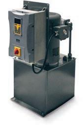
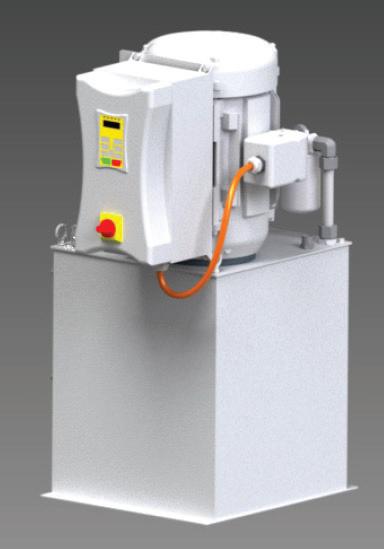
Parker’s DCP PAK (Drive Controlled PAK) is our H Pak power unit with SSD’s AC10 inverter. The AC10 is mounted, wired, configured and factory tested. Simply connect power per local safety regulations, fill the unit with oil and you’re ready to run. The AC10 has a lockable disconnect mounted on the front of the unit and has an IP66 rating.
Parker’s DCP Pak (Drive Controlled Pak) is our H Pak power unit with SSD’s AC10 inverter. The AC10 is mounted, wired, confgured and factory tested. Simply connect power per local safety regulations, fll the unit with oil and you’re ready to run. The AC10 has a lockable disconnect mounted on the front of the unit and has an IP66 rating.
Reliability & Energy Savings
Reliability & Energy Savings
1. Parker’s DCP Pak saves energy and improves reliability compared to units that use normal motor starters.
Parker’s DCP PAK saves energy and improves reliability compared to units that use normal motor starters.
2. If rush current is eliminated, the unit reduces power consumption and wear on the motor and couplings.
1. In rush current is eliminated, reducing power consumption and wear on the motor and couplings.
3. The unit’s operation can be set to match the system demand, resulting in less power consumption.
2. The unit can be set to run only as much as is needed to match the system demand, less power consumption.
4. Less heat generation improves component and oil life.
3. Less heat generation, improving component and oil life.
5. Most applications run at least part time below 1800 RPM, resulting in quieter operation.
4. Quieter operation since most applications will run at least part time below 1800RPM.
6. Less running time at max RPM improves component life, especially for the pump and motor.
5. Less running time at max RPM improves component life, especially the pump and motor.
7. A constant 95% power factor results in more effcient use of the electric motor, especially on larger motors that are only partially loaded and aren’t controlled by an inverter.
6. Constant 95% power factor. This results in more efficient use of the electric motor, especially on larger motors that are only partially loaded and aren’t controlled by an inverter.
7. Ability to start and stop the motor as often as neces sary without damaging the motor. Less wear and tear on the pump/motor coupling and reduced power consumption due to reduced in -rush current.
8. The unit has the ability to start and stop the motor as often as necessary without damaging the motor. This results in less wear and tear on the pump/motor coupling and reduced power consumption due to reduced in-rush current.
Dual Rated CE Motors: While using a dual rated motor is not necessary when using an inverter, customers often request motors with a “CE” certifcation. If you require a motor with the “CE” mark, select the “D” prefx in the motor horsepower section of the H Pak model code. For example, “DL” will select a dual rated CE marked 5Hp (L) motor
Dual Rated CE Motors: While using a dual rated motor is not necessary when using an inverter, customers often request motors with a “CE” certification. If you require a motor with the “CE” mark, select the “D” prefix in the motor horsepower section of the H PAK model code. For example, “DL” will select a dual rated CE marked 5Hp (L) motor.
32
Parker Hannifin Corporation Hydraulic Pump and Power Systems Division Marysville, Ohio USA
Introduction
HY28-2661-CD/US
HY28-2661-CD/US
Introduction
Hydraulic Power Units H-Pak with DCP
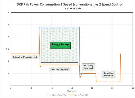
Sample Power Comparison When Used on a Transfer, Clamp and Transfer Application.
Sample power comparison when used on a transfer, clamp and transfer application.
The blue line represents the power consumed using a single speed pump. The orange line shows the power consumption using a Parker DCP in 2 speed mode.
The blue line represents the power consumed using a single speed pump. The orange line shows the power consumption using a Parker DCP in 2 speed mode.
Cumulative Power Usage:
Cumulative Power Usage: 0 0.2 0.4 0.6 0.8 1 1.2 1.4 1.6 1.8
Parker Hannifin Corporation
Hydraulic Pump and Power Systems Division Marysville, Ohio USA
KWHrsAccum
2‐spd KWHrs1‐spd
KWHrs KWH
HY28-2661-CD/US Safety & Technical Information
Available Confgurations:
Hydraulic Power
H-Pak with DCP
Units
PARKER’S DCP Pak is available in 5 factory set options. The software and settings that are required for the selected option will be downloaded and tested before the unit is shipped. The 5 options are described in the following section. Once the unit is received, it can be installed and used without any programming from the customer. If desired, some variables can be adjusted via the unit’s keypad, or additional edits can be performed by using a laptop computer. For detailed information regarding the drive, please refer to the drive’s product manual HA502703U001, available at www.parker.com or contact Parker’s SSD Division.
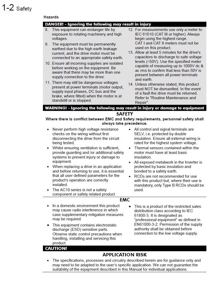
It is the customer’s responsibility to install this equipment to meet all required safety standards. Proper electrical isolation for maintenance and arc fash control must be provided.
WARNING: Branch circuit protection with a maximum rating of 5KA current limiting must be supplied per local electrical codes. WA

34
Parker Hannifin Corporation Hydraulic Pump and Power Systems Division Marysville, Ohio USA
Safety & Technical Information
While ensuring ventilation is suffcient, provide guarding and/or additional safety systems to provide injusry or damage to equipment.
Hydraulic Power Units H-Pak with DCP
HY28-2661-CD/US ! !
Parker Hannifin Corporation Hydraulic Pump and Power Systems Division Marysville, Ohio USA
m
HY28-2661-CD/US
Safety & Technical Information
Control Options
Control Options
Hydraulic Power Units H-Pak with DCP
Analog speed control: You can provide either a 4-20mA (option I) or 0-10VDC (option V) command signal to control RPM. The unit will be pre-configured based on your model code selection and is scaled to operate between 500 RPM at minimum signal and 2000 RPM at maximum signal. One digital signal (contact closure or 24VDC source) is required to enable the drive and another is required to start and stop the drive. The min and max values can be changed (ref to the AC10 operating manual) but it is not recommended that the minimum setting be set any lower and that the maximum setting not be set any higher. Pump efficiency drops dramatically below 500RPM and pump and or motor damage may result with speeds above 2200RPM.
Analog Speed Control: You can provide either a 4-20mA (option I) or 0-10VDC (option V) command signal to control RPM. The unit will be pre-confgured based on your model code selection and is scaled to operate between 500 RPM at minimum signal and 2000 RPM at maximum signal. One digital signal (contact closure or 24VDC source) is required to enable the drive and another is required to start and stop the drive. The min and max values can be changed (ref to the AC10 operating manual) but it is not recommended that the minimum setting be set any lower and that the maximum setting not be set any higher. Pump effciency drops dramatically below 500RPM and pump and or motor damage may result with speeds above 2200RPM.
CAUTION: Disabling the drive DOES NOT remove power from the motor. High voltage can be present at the motor leads even when the motor is not running. To ensure the motor is safe to wire, make sure the disconnect is locked in the OFF position, incoming power is removed and the AC10’s display and LED’s are off, indicating the capacitors are discharged.
CAUTION: Disabling the drive DOES NOT remove power from the motor. High voltage can be present at the motor leads even when the motor is not running. To ensure the motor is safe to wire, make sure the disconnect is locked in the OFF position, incoming power is removed and the AC10’s display and LED’s are off, indicating the capacitors are discharged.
* The default switch setting when ordering voltage control (option V) will be 0-10VDC. If 0-5VDC is required the customer must change the switch settings for 0-5VDC.
* The default switch setting when ordering voltage control (option V) will be 0-10VDC. If 0-5VDC is required the customer must change the switch settings for 0-5VDC.
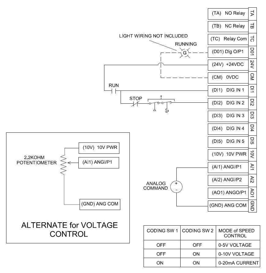
If DI2 is not used, install a jumper between DI1 and DI2.
If DI2 is not used install a jumper between DI1 and DI2.
Parker Hannifin Corporation Hydraulic Pump and Power Systems Division Marysville, Ohio USA
36
*
HY28-2661-CD/US
Safety & Technical Information
Hydraulic Power Units H-Pak with DCP
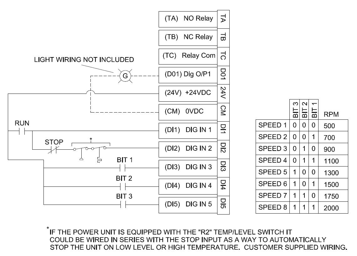
Discrete Speed Control: If option “D” is selected the unit will be confgured to operate at 8 different speeds based on the combination of making 3 inputs active. There are also two discrete inputs that need to be wired by the customer to enable the drive. DI1 and DI2 need to be “ON” (held at 24VDC) to start the drive. If either input goes low the unit will stop. See the wiring example below. The unit will be factory set to operate at the speeds shown in the diagram. These speeds can be changed by the customer using the keypad or computer interface (ref to the AC10 operating manual).
Discrete speed control: If option “D” is selected the unit will be configured to operate at 8 different speeds based on the combination of making 3 inputs active. There are also two discrete inputs that need to be wired by the customer to enable the drive. DI1 and DI2 need to be “ON” (held at 24VDC) to start the drive. If either input goes low the unit will stop. See the wiring example below. The unit will be factory set to operate at the speeds shown in the diagram. These speeds can be changed by the customer using the keypad or computer interface (ref to the AC10 operating manual).
CAUTION: Disabling the drive DOES NOT remove power from the motor. High voltage can be present at the motor leads even when the motor is not running. To ensure the motor is safe to wire, make sure the disconnect is locked in the OFF position, incoming power is removed and the AC10’s display and LED’s are off, indicating the capacitors are discharged.
CAUTION: Disabling the drive DOES NOT remove power from the motor. High voltage can be present at the motor lea ds even when the motor is not running. To ensure the motor is safe to wire, make sure the disconnect is locked in the OFF position, incoming power is removed and the AC10’s display and LED’s are off, indicating the capacitors are discharged.
If DI2 is not used, install a jumper between DI1 and DI2.
If DI2 is not used install a jumper between DI1 and DI2.
37
USA
Parker Hannifin Corporation Hydraulic Pump and Power Systems Division Marysville, Ohio
Safety & Technical Information
Hydraulic Power Units H-Pak
with DCP
Auto 2 Speed based on motor current: This configuration (option “Q”) will run at full rated speed (1800RPM) and then automatically drop to minimum speed (600RPM) when the motor current exceeds a certain value. This speed change is not internally triggered, it is accomplished using an output wired to an input. The unit will have a jumper wire that connects relay output TA to DI3. When the max current level is exceeded TA turns on, bringing DI3 high. When DI3 is high the unit runs at minimum speed. This configuration works well in clamping circuits where initial cylinder movement is rapid with low resistance followed by stalling at clamping pressure and very little flow. If the jumper between TA and DI3 is removed or controlled externally additional possibilities can be realized based on how the customer manipulates DI3. For example, a pressure switch or PLC could be used alone or with DI3 to reduce speed. There are also two discrete inputs that need to be wired by the customer to enable the drive. DI1 and DI2 need to be “ON” (held at 24VDC) to start the drive. If either input goes low the unit will stop.
Auto 2 Speed Based on Motor Current: This confguration (option “Q”) will run at full rated speed (1800RPM) and then automatically drop to minimum speed (600RPM) when the motor current exceeds a certain value. This speed change is not internally triggered. It is accomplished using an output wired to an input. The unit will have a jumper wire that connects relay output TA to DI3. When the max current level is exceeded TA turns on, bringing DI3 high. When DI3 is high the unit runs at minimum speed. This confguration works well in clamping circuits where initial cylinder movement is rapid with low resistance followed by stalling at clamping pressure and very little fow. If the jumper between TA and DI3 is removed or controlled externally additional possibilities can be realized based on how the customer manipulates DI3. For example, a pressure switch or PLC could be used alone or with DI3 to reduce speed. There are also two discrete inputs that need to be wired by the customer to enable the drive. DI1 and DI2 need to be “ON” (held at 24VDC) to start the drive. If either input goes low the unit will stop.
Factory settings for option Q: When motor current > 95% FLA, DO1 turns on. See F310 in AC10 manual. When motor current < 75% FLA, DO1 turns off. See F311 in AC10 manual.
Factory settings for option Q: When motor current > 95% FLA, DO1 turns on. See F310 in AC10 manual.
F310 is an absolute number, ie 19 amps.
When motor current < 75% FLA, DO1 turns off. See F311 in AC10 manual.
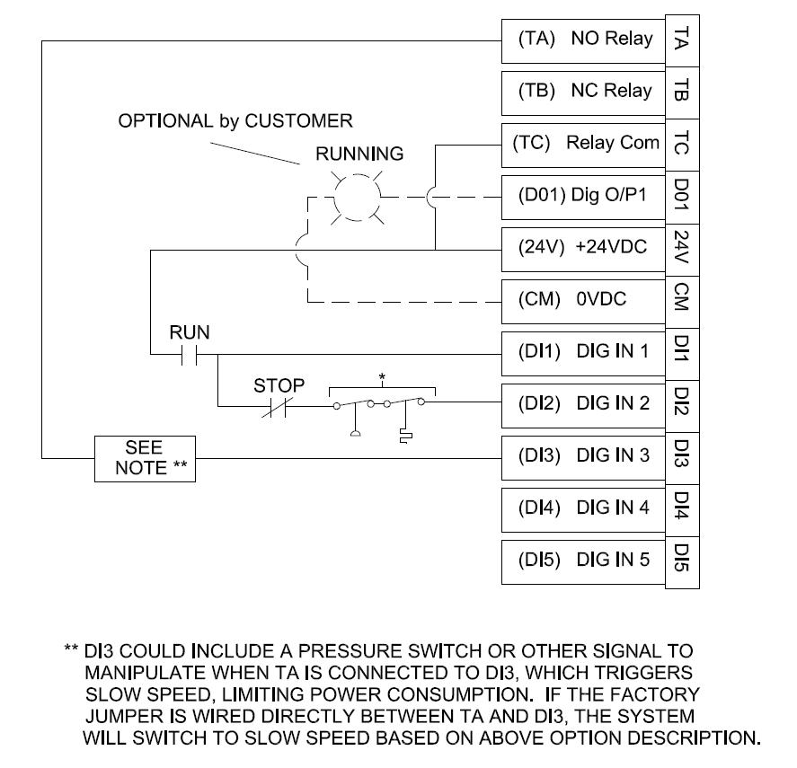
F310 is an absolute number, ie 19 amps.
F311 is a percentage, ie 15%. DO1 turns on when the motor current exceeds 19 amps and turns off when the motor current is less than (19-19x15%) or 16.15 amps.
F311 is a percentage, ie 15%. DO1 turns on when the motor current exceeds 19 amps and turns off when the motor current is less than (19-19x15%) or 16.15 amps.
These values can be changed by the customer using the keypad or computer interface (ref to the AC10 operating manual).
These values can be changed by the customer using the keypad or computer interface (ref to the AC10 operating manual).
NOTE: If your application requires a lot of force during pre-travel or consumes flow during clamping, the system may hunt as the motor current crosses the MIN and MAX current levels. Option D (speed determined by inputs, not current) may be a better option in these cases.
NOTE: If your application requires a lot of force during pre-travel or consumes fow during clamping, the system may hunt as the motor current crosses the MIN and MAX current levels. Option D (speed determined by inputs, not current) may be a better option in these cases.
CAUTION: Disabling the drive DOES NOT remove power from the motor. High voltage can be present at the motor leads even when the motor is not running. To ensure the motor is safe to wire, make sure the disconnect is locked in the OFF position, incoming power is removed and the AC10’s display and LED’s are off, indicating the capacitors are discharged.
CAUTION: Disabling the drive DOES NOT remove power from the motor. High voltage can be present at the motor leads even when the motor is not running. To ensure the motor is safe to wire, make sure the disconnect is locked in the OFF position, incoming power is removed and the AC10’s display and LED’s are off, indicating the capacitors are discharged.
If DI2 is not used install a jumper between DI1 and DI2.
If DI2 is not used install a jumper between DI1 and DI2.
38
HY28-2661-CD/US
Parker Hannifin Corporation Hydraulic Pump and Power Systems Division Marysville, Ohio USA
HY28-2661-CD/US
Safety & Technical Information
Soft Start: Option “S” is simply a soft start application. When enabled the motor will accelerate to max RPM (factory set at 1800RPM) over 2 secs. This option can help protect the couplings and pump from wear and like all the above options, inrush current is controlled to minimize motor winding stresses. It also gives the pump a better chance to properly prime before full flow is achieved.
Hydraulic Power Units H-Pak with DCP
Soft Start: Option “S” is simply a soft start application. When enabled the motor will accelerate to max RPM (factory set at 1800RPM) over 2 secs. This option can help protect the couplings and pump from wear and like all the above options, inrush current is controlled to minimize motor winding stresses. It also gives the pump a better chance to properly prime before full fow is achieved.
CAUTION: Disabling the drive DOES NOT remove power from the motor. High voltage can be present at the motor leads even when the motor is not running. To ensure the motor is safe to wire, make sure the disconnect is locked in the OFF position, incoming power is removed and the AC10’s display and LED’s are off, indicating the capacitors are discharged.
OPTIONAL BY CUSTOMER
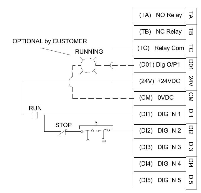
If DI2 is not used install a jumper between DI1 and DI2.
CAUTION: Disabling the drive DOES NOT remove power from the motor. High voltage can be present at the motor leads even when the motor is not running. To ensure the motor is safe to wire, make sure the disconnect is locked in the OFF position, incoming power is removed and the AC10’s display and LED’s are off, indicating the capacitors are discharged. If DI2 is not used, install a jumper between DI1 and DI2.
39
Parker Hannifin Corporation Hydraulic Pump and Power Systems Division Marysville, Ohio USA
HY28-2661-CD/US Safety & Technical Information
AC10 Part Numbers:
HPVoltage Hp/Voltage
2
Incoming Power 230VAC 3 Phase
AC 10 Part Numbers
16G-31-0070-BF-DT
Hydraulic Power Units H-Pak with DCP
2
4
Incoming Power 460VAC 3 Phase
16G-41-0040-BF-DT 3 2
Incoming Power 230VAC 3 Phase
16G-31-0100-BF-DT 4
Incoming Power 460VAC 3 Phase
16G-41-0065-BF-DT 54
Incoming Power 460VAC 3 Phase
16G-41-0090-BF-DT 7.54
Incoming Power 460VAC 3 Phase
16G-42-0120-BF-DT 104
Incoming Power 460VAC 3 Phase 16G-42-0170-BF-DT 154
Incoming Power 460VAC 3 Phase
Incoming Power 460VAC 3 Phase 16G-43-0320-BF-DT
16G-43-0230-BF-DT 204
AC10 Power Ratings:
3Ph 230V
16G-31-0025-BF0.44.32.58.2 95 16G-31-0045-BF0.757.64.511.5 95 16G-31-0070-BF1.512.0718.2 96 16G-31-0100-BF2.214.31021.5 96
3Ph 400V
16G-41-0020-BF0.754.126.5 95 16G-41-0040-BF1.56.9411.0 96 16G-41-0065-BF2.29.66.515.0 96 16G-41-0080-BF3.711.6818.0 96 16G-41-0090-BF4.013.6921.0 96 16G-42-0120-BF5.518.81229.0 96 16G-42-0170-BF7.522.11734.0 96 16G-43-0230-BF1130.92346.5 97 16G-43-0320-BF15523280.0 97
40
Parker Hannifin Corporation Hydraulic Pump and Power Systems Division Marysville, Ohio USA
SupplyPart NumberkW Input Current (A) Output Current (A) Input Protection Current Esitmated Efficiency Inductance of Output Choke (mH)
HY28-2661-CD/US Notes
Hydraulic Power Units H-Pak with DCP
41
Parker Hannifin Corporation Hydraulic Pump and Power Systems Division Marysville, Ohio USA
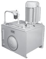
42 Parker Hannifin Corporation Hydraulic Pump and Power Systems Division Marysville, Ohio USA HY28-2661-CD/US Introduction Hydraulic Power Units V-Pak Low Profile Series Catalog HY13-1552-002/US,EU Volume Control Low Profile Power Units Series V-Paks Parker Hannifin Corporation Hydraulic Pump
Marysville, Ohio USA 2 Introduction Low ProfileTank Size Pump Flow Electrical MotorsMaximum V-PakLiters (Gallon)LPM (GPM) @ 1800 RPM KW (HP) BAR (PSI) V8 302.8 (80) 136.7 (36.1) 5.6 - 30 (7 1/2 - 40) 207 (3000) Quick Reference Data Chart PUMP COMPENSATOR CONTROL SINGLE REMOVABLE TOPPLATE GLYCERINE FILLED PRESSURE GUAGE WITH SHUT-OFF VALVE PUMP CASE PREFILL PORT PRESSURE PORT RETURN PORT SAE-12 RESERVOIR DRAIN SAFETY RELIEF VALVE Standard Features •Vertical Design •Submerged Pump •Precision Pump Mounting Adapters •Suction Strainer •Glycerine Filled Pressure Gage with Shut Off •Oil Level Gage with Thermometer •Remote Compensator and Safety Relief •Breather and Fill Cap •1800 RPM Motor •Drain Plug •Clean Out Cover •Single Removable Topplate •Extra SAE-20 Return Port •All Hydraulic Connections SAE Straight Thread Benefits •Saves Floor Space •Positive Pump Inlet •Longer Pump Life •Protects Pump from Contamination •Improved Diagnostics •Helps
Trouble-Free Perfor mance •Protects
System Shock •Easy to Fill Tank, Control
of Airborne Contaminants •More Flow at Less Cost •Allows Drainage of Fluid •Easy Access to Inside of Reservoir •Easy Servicability of Internal Components •Allows Flexibility for Customer Return Plumbing •No Leaks FILLER/BREATHER OIL LEVEL GUAGE WITH THERMOMETER 406mm (16") CLEANOUT COVER
REMOVABLE TOP PLATE
Division
to Maintain
Against
Ingression
SINGLE
HY28-2661-CD/US Hydraulic Power Units
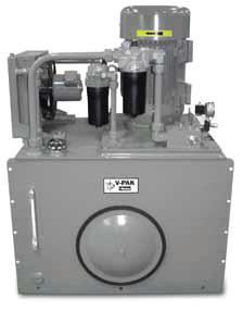
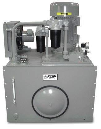
HY28-2661-CD/US
V-Pak Low Profile Series Introduction
Introduction
Performance Data
Standard Features
•Ver tical Design
• Submerged Pump
•Precision Pump Mounting Adapters
• Suction Strainer
•Glycerine Filled Pressure Gage with Shut Off
•Oil Level Gage with Thermometer
•Relief Valve
•External Pump Compensator Control
•Breather and Fill Cap
•1800 RPM TEFC Motor
• Cleanout Cover
•Pressure and Return Port Block with Safety Relief
•Remote Pump Compensator Control Valve
Options
•D05 (D02) Single Station Manifold with Safety Relief
• D05 (D02), D08 (D06) Multi-Station Manifold with Safety Relief
• Pressure & Return Filters (10 Micron)
• Variety of Manapak Sandwich Valves
• Heat Exchangers (Air/Oil)
• Combination Temp/Float Switch - Temp Fixed
• Single Pressure Remote Compensator
• Single Pressure Remote Compensator with Low Pressure Standby
• Bi-Pressure Remote Compensator
• Bi-Pressure Remote Compensator with Low Pressure Standby
• Load Sensing (Flow Control)-Consult Factory
• Horsepower Limiting-Consult Factory
• Rated 50/60Hz Motors
Specifications
Parker “V-Pak” Hydraulic Power Units are vertical design, 303 liter (80 gallon) reservoirs utilizing Parker Variable Volume Piston Pumps.
Warranty
Schematic Symbol (Basic Unit)
Installation Data: See page 19 of this catalog or Parker Installation/ Maintenance Manual for specific recommendations pertaining to start-up, system cleanliness, fluids, temperatures and other important factors relative to proper installation and use of these power units.
Parker Hannifin Corporation
Parker Hannifin Cor poration
Hydraulic Pump and Power Systems Division Marysville, Ohio USA
Hydraulic Pump Division Marysville, Ohio USA
43
Hyd
cPum
n Ma
3 SAE-20 SPARE RETURN SAE -12 M X “O” OPTION MANIFOLD “OMIT” OPTION COMP CONTROL V-PAK BASIC UNIT NO OPTIONS OR ACCESSORIES “OMIT” OPTION PUMP COMPENSATOR “O” OPTION MANIFOLD P T SUPPLY PORT SAE-16 RETURN PORT SAE-20
Hydraulic Power Units V-Pak Low Profile Series Introduction Catalog HY13-1552-002/US,EU Volume Control LowProfilePower Units SeriesV-Paks Parker Hannifin Corporation
rauli
p Divisio
rysville, Ohio USA
components
are warranteed for
year.
warranty may
extended
The hydraulic
on these Parker Power Units
one
This
be
to three years by using and properly maintaining Parker filters
Pump Tank Size Pump Flow Electrical MotorsMaximum Model Liters (Gallon)LPM (GPM) @ 1800 RPMKW (HP) BAR (PSI)
V8 302.8 (80) 136.7 (11.0-36.1)5.6 - 30 (7 1/2 - 40)207 (3000)
Pressure Control Pump Control
Reduced Flow OR
Pump Flow
D = Dual Rated• W = No Motor••
If No Motor or Dual Rated Code
Electric Motor Manifold
Electric Motor Description
HP (KW) - RPM Frame Phase
W M 213TC (no motor)
M 7.5 (5.6) - 1725 - 213TC - 3
D M 7.5 (5.6) - 1725 - 213TC - 3 DUAL RATED
W N 215TC (no motor)
N 10 (7.5) - 1725 - 215TC - 3
D N 10 (7.5) - 1725 - 215TC - 3 DUAL RATED
W P 254TC (no motor)
P 15 (11.2) - 1725 - 254TC - 3
D P 15 (11.2) - 1725 - 254TC - 3 DUAL RATED
W S 256TC (no motor)
S 20 (14.9) - 1725 - 256TC - 3
D S 20 (14.9) - 1725 - 256TC - 3 DUAL RATED
W Q 284TC (no motor)
Q 25 (18.6) - 1725 - 284TC - 3
D Q 25 (18.6) - 1725 - 284TC - 3 DUAL RATED
Code Pump Control
Omit Std. Remote Compensator A* Load Sense Flow Control
*Unless otherwise specified, a SAE-6 37° flared port will be supplied for customer connection.
**Consult factory for horsepower and hi-lo pump control options. Lead time is four weeks.
Code Pump Flow Rate @1800 RPM Pump Used and Description
15 15.6 GPM (59 LPM)PVP33 - Std. Remote Compensator 23 23.0 GPM (87 LPM)PVP48 - Std. Remote Compensator 36 36.1 GPM (137 LPM) P2075 - Std. Remote Compensator
* Specify in GPMDestroked (Reduced) Flow
*Unless otherwise specified, units are shipped at max. flow rate (GPM) at 1800 RPM.
When reduced flow setting is required, Reduced flows from 22.5 to 8.0 GPM (85.2 to 30.3 LPM), specify in 0.5 GPM increments.
Reduced flows from 35.0 to 24.0 GPM (132.5 to 90.8 LPM), specify in 1.0 GPM (3.8 LPM) increments.
Example: V*9.5**-- = PVP33 Pump destroked to 9.5 GPM (36.0 LPM)
V*A31**-- = P2075 Load Sense Pump destroked to 31.0GPM (177.3 LPM)
•Use D prefix to specify dual rated motor. When ordering, D must be followed by the motor model code.
NOTE:
1. Manifolds are mounted vertically.
Bottom station is number 1.
2. M5-3 and 5 station available. M8-2 station available.
= Omit if not required
W R 286TC (no motor)
R 30 (22.4) - 1725 - 286TC - 3
D R 30 (22.4) - 1725 - 286TC - 3 DUAL RATED
W V324TC (no motor)
V40 (29.8) - 1725 - 324TC -3
D V40 (29.8) - 1725 - 324TC -3
Three phase electric motors are rated as follows: 208-230/460V, 3PH, TEFC - 60 Hertz 1800 RPM 1.15 SF
• Dual rated motors include the 60Hz ratings plus 190/380V 50Hz (1.0SF) 1450RPM 10:1CT/20:1VT INVERTER RATED UR/CSA/CSA EEV/CE
• Dual rated motors may have longer than standard leadtime. Options G & K3 are dual rated as standard.
Consult factory for other motor speeds (RPM) and voltages.
•• Use W prefix when no motor is required on unit. When ordering, W must be followed by motor model code equivalent to frame size of motor to be used.
DO NOT USE “W” and “D” together I.E: 213TC unit with no motor is called out “WM”.
C Station #4: B Station #5: C
44
V-Pak
Profile Ordering Information
Power Units V-Pak
V8 Reservoir Size 80 Gallons (302.8 Liters)
Pressure Control
B
BJ
C
CJ
D
DJ
F
Code Porting Block/Subplate or Manifold Type Supply/Return Port or Actuator Port Size Other Omit Pressure and Return Port Block with Safety Relief Valve P Port SAE-16 T Port SAE-20 None S5 D05 Single Station Subplate with Safety Relief Valve A & B Ports SAE-10 Str. Thr'd None M5* (2) D05 Multistation
Safety Relief and Pump Compensator Valves A & B Ports SAE-8 Str. Thr'd None M82 (3) D08 Two Parallel Circuit Manifold with Safety Relief and Pump
Valves A & B Ports SAE-16 Str.
Parker Hannifin Corporation Hydraulic Pump and Power Systems Division Marysville, Ohio USA HY28-2661-CD/US
Low
Hydraulic
Low Profile Series
Code
Omit Single Pressure Remote Compensator
Single Pressure Remote Compensator with Low Pressure Standby
Single Pressure Remote Compensator with Low Pressure Standby, 24 VDC
Bi-Pressure Remote Compensator
Bi-Pressure Remote Compensator, 24VDC
Bi-Pressure Remote Compensator with Low Pressure Standby
Bi-Pressure Remote Compensator with Low Pressure Standby, 24VDC
Provision for Customer Supplied Remote Control Relief Valve
Parallel Circuit Manifold with
Compensator
Thr'd Y Port SAE-8 Str. Thr'd *When ordering Multi-Station Manifolds, the number of stations must be specified. If valves are to be mounted, specify the valves and sequence, if the model code exceeds 25 digits, call factory. Example: V815QM53BCB1 Example: V815QM55B1B1CBC 3 Station D05 Manifold 5-Station D05 Manifold Station #1: B Station #1: B1 Station #2: C Station #2: B1 Station #3: B1 Station #3:
A* Continuous Pump Case Cooling RM-08-2-2
Air/Oil: .8Hp (.6KW) Rej Available on 7.5Hp thru 25Hp (5.6 -18.5KW) motors B* Continuous Pump Case Cooling RM-19-2-2 Air/Oil: 1.5Hp (1.1KW) Rej C#^ Filter Cooling Loop AOC-22-2-1PH 40CN205Q
E#^ Return Line Heat Exchanger EKS-708-T
F^ Water valve/ bulbwell 65253 + bulbwell + 3/4" weld coupling
H Pressure Filter30P210QM250NN1
J 2" Weld coupling for customer supplied heater
K Check
Air/Oil w/1PH Motor: Oil flow 8GPM (30LPM) 4.5Hp (3.3KW) heat rejection Includes 3/4" weld coupling for customer supplied device (Temp switch for fan)
Water/oil: 17Hp (12.7 KW)Rej @ 20GPM Oil Flow 2:1 Flow ratio Max oil Flow 60GPM Max water flow 12 GPM Includes 3/4" weld coupling for customer supplied device
If ordered without option E this option will only include the 3/4" weld coupling.
10 Micron Microglass II Dual Element, Mechanical Indicator
Ordering Information P
Valves Function
45 Parker Hannifin Corporation Hydraulic Pump and Power Systems Division Marysville, Ohio USA HY28-2661-CD/US Hydraulic Power Units V-Pak Low Profile Series V-Pak Low Profile
Code Manapak Control
Valve Model Number NFPA Mounting Pad Nominal Flow GPM (LPM) Circuit Symbol 1 FM3DDKND05D057 (26.5) 3 CPOM3DDND05D057 (26.5) *Manapak valves mounted in order of callout. First valve will be nearest DCV; last valve will be on manifold. Code Options and Accessories Function Model Number Technical Data
Code Directional Control Valve Valve Model Number NFPA Mounting Pad Nominal Flow GPM (LPM) DescriptionCircuit Symbol B
C
Double
Directional Control Valve Manapak Control Valves• Options and Accessories =
PT AB AB PT
Valve Pump Outlet 493-16-D1-2 5 PSI (0.3 bar) Cracking Pressure L Bypass CheckC2020S65 65 PSI (4.6 bar) Cracking Pressure N Return Filter40CN210Q 10 Micron Microglass II Dual Element, Mechanical Indicator** (8 PSID) R1 Combination Float/Temp. Switch N.O. Float Up 877501 Fixed Temp at 65°C (149°F) Close @ Low Level and/or 65°C (149°F) (N.O.) R2 Combination Float/Temp. Switch N.C. Float Up 877502 Fixed Temp at 65°C (149°F) Open @ Low Level and/or 65°C (149°F) (N.C.) *Heat rejection based on 72 deg F differential between the oil and the ambient temperature. #Heat rejection based on 40deg F differential between tranfer medium. ^ May require longer than standard lead time. DO NOT select more than one offline loop, A or B or C. C & E cannot be selected together.
D3W1CNYCCFD0520 Double (Spr. Ctr)
D3W4CNYCCFD0515
(Spr. Ctr)
Omit if not required
HY28-2661-CD/US Hydraulic Power Units
HY28-2661-CD/US CatalogHY13-1552-002/US,EU
Hydraulic Power Units V-Pak Low Profile Series Installation Information
TechnicalInformation
Dimensions – Basic V-Pak Low Profile
Shown with “Omit” Option Manifold
Volume Control LowProfilePowerUnits SeriesV-Paks
Inch equivalents for millimeters dimensions are shown in (**). Installation information is for reference only, consult factory or visit Parker's Econfigurator for detailed information.
FILTER BREATHER (STANDARD)
"B" 273.1 (10.75)
231.7 (9.12)
819.2 (32.25)
Dimension
M 7.5 (5.6) - 1725 - 213TC - 3 N/A
458(18)
N 10 (7.5) - 1725 - 215TC - 3 N/A 473 (18.6)
P 15 (11.2) - 1725 - 254TC - 3 48 (1.88) 522 (20.5)
S 20 (14.9) - 1725 - 256TC - 3 48 (1.88) 522 (20.5)
Q 25 (18.6) - 1725 - 284TC - 3 51 (2.0) 611 (24)
R 30 (22.4) - 1725 - 286TC - 3 51 (2.0) 611 (24)
72.9 (2.87) 736.6 (29.0) 838.2 (33.0) 914.4 (36.0)
SAE-20 SPARE RETURN PORT (AVAILABLE WITHOUT RETURN FILTER ONLY)
SAFETY RELIEF VALVE
MAINTAIN 31 BAR (450 PSI) ABOVE PUMP COMPENSATOR CONTROL SETTING
TOPPLATE LIFTING EYE TYP.-3 PLCS.
CLEAN-OUT COVER FULL MARK
V-PAK
SAE-12 TANK DRAIN 952.5 (37.5) 990.6 (39.0)
T P
SUPPLY PORT
SAE-16 ORB
RETURN PORT SAE-20 ORB "O" OPTION MANIFOLD
V 40 (29.8) - 1725 - 324TC -3 144 (5.69) 789 (31)
REMOTE PUMP COMPENSATOR CONTROL ADJUSTMENT
PUMP CASE FILL PORT PRESSURE GUAGE WITH SHUT-OFF VALVE
* Reference dimension consult factory if critical to application.
SAE-20 SPARE RETURN PORT 725 (28.56) 432 (17.0)
Ø15.9 (.625) TYP. -4 PLCS. 63.5 (2.50) 720.3 (28.36) 769.5 (31.36) 878.6 (34.59)
HydraulicPump Division Marysville,OhioUSA 6
68.6 (2.70)
"A"*
ParkerHannifinCorporation
V-Pak Low Profile Series Installation Information 30
46 Parker Hannifin Corporation Hydraulic Pump and Power Systems Division Marysville, Ohio USA
Parker Hannifin Cor poration Hydraulic Pump Division Marysville, Ohio USA
"A" Code MotorMotor Description H(WK)P-RPM-Frame-Type "B"
HY28-2661-CD/US Technical Information
Hydraulic Power Units
V-Pak Low Profile Series Catalog HY13-1552-002/US,EU
Technical Information
V-Pak Low Profile S5 Manifold Options
Volume Control Low Profile Power Units Series V-Paks
S5 SUBPLATE OPTION FOR USE WITH D3W VALVE (NFPA D05)
T P
Parker Hannifin Corporation Hydraulic Pump and Power Systems Division Marysville, Ohio USA
71.4 (2.81) 38.1 (1.50) 54.1 (2.13) T
26.9 (1.06)
RETURN PORT SAE-12 RETURN PORT SAE-12 RETURN PORT SAE-12
X T P X X B A
"A" PORT SAE-10 "B" PORT SAE-10 PUMP SUPPLY
D05 MNTG SURFACE
Hydraulic Pump Division Marysville, Ohio USA 7
47
Parker Hannifin Corporation
A-D05 B-D03 B-D05 A-D03
Inch equivalents for millimeters dimensions are shown in (**)
X P
SUPPLY PORT SAE-12
Technical
Parker Hannifin Corporation Hydraulic Pump Division Marysville, Ohio USA
Parker Hannifin Corporation Hydraulic Pump and Power Systems Division Marysville, Ohio USA
48
HY28-2661-CD/US Hydraulic Power Units V-Pak Low Profile Series Technical Information Catalog HY13-1552-002/US,EU Volume Control Low Profile Power Units Series V-Paks
T P A A B B Y G
AB X
AB T T P Y "Y"
G
P "A"&"B"PORTS RETURN M82 2 STATION MANIFOLD OPTION FOR USE WITH NFPA D08 VALVES SAE-8 "Y" PORT, NO "X" PORT 3
5
PER
1.25 SAE-6 "G" G B A T P G B B A A T P X 3 AND 5 STATIONS SAE-8 "A"&"B"PORTS SURFACE MNTG D05 SAE-12 PORT RETURN B A SUPPLY PUMP M53 AND M55 3 AND 5 STATION MANIFOLD OPTIONS FOR USE WITH NFPA D05 VALVES
8
266.7 (10.50) 46.0 (1.81) 26.9 (1.06) 66.8 (2.63) 50.8 (2.00) 133.4 (5.25) -16 SAE (2 STATIONS)
PORT SAE-16
SAE-8
"G" -6 SAE
AND
STATION AVAIL. 83.0 (3.25)
STATION 165.0 (6.5) 83.0 (3.25) 40.0 (1.56) 54.0 (2.12) 17.5 (0.69)
equivalents formillimeters
Option"
Information V-Pak Low Profile M53/M55 & M82 Manifold Options Inch
dimensions are shown in (**). "M53/M55 Option" "M82
HY28-2661-CD/US
9 Technical Information
Parker Hannifin Corporation
Hydraulic
Hydraulic Pump Division Marysville, Ohio USA
49
Hydraulic Pump and Power Systems Division Marysville, Ohio USA Power Units
V-Pak Low Profile Series Technical Information Catalog HY13-1552-002/US,EU Volume Control Low Profile Power Units Series V-Paks
Parker Hannifin Corporation
equivalents for millimeters dimensions are shown in (**) PRE-FILL PORT PUMP CASE PRE-FILL PORT PUMP CASE HI PRE-FILL PORT PUMP CASE SOL LO SOL HI PRE-FILL PORT PUMP CASE PRE-FILL PORT PUMP CASE AUX.VENT PORT (SAE-6) -6 SAE P P AND MANUAL OVERRIDE WITH DIN.43650 CONNECTOR SOLENOIDS ARE LOW WATT SOL HIGH PSI HIGH STANDBY LOW SOL T P PSI LOW SOL HIGH PSI HIGH T P PSI LOW AND MANUAL OVERRIDE WITH DIN.43650 CONNECTOR SOLENOID IS LOW WATT SUPPLIED REMOTE COMPENSATOR ATTACH POINTS FOR CUSTOMER SAE-6 37˚ FLARE "P" & "T" PORTS TANK (RETURN) PORT PUMP COMPENSATOR PRESSURE (INLET) PORT PUMP COMPENSATOR 37˚ FLARE SAE-6 PT T P AND MANUAL OVERRIDE WITH DIN.43650 CONNECTOR SOLENOID IS LOW WATT T P REMOTE COMPENSATOR CUSTOMER SUPPLIED PROVISION FOR "E" OPTION SOL HIGH PSI HIGH STANDBY LOW SOL T PSI LOW W/LOW PRESS STANDBY REMOTE COMPENSATOR BI-PRESSURE "D" OPTION REMOTE COMPENSATOR BI-PRESSURE "C" OPTION ENERGIZE FOR LOW PRESSURE LOW PRESS. STANDBY (N.O.) HIGH PRESS. CONTROL PUMP COMPENSATOR LOW PRESS. CONTROL PUMP COMPENSATOR ENERGIZE FOR HIGH PRESSURE HIGH PRESS. SOLENOID (N.O.) SOL LO SOL HI HI LOW PRESS.CONTROL PUMP COMPENSATOR ENERGIZE FOR HIGH PRESSURE HIGH PRESS.SOLENOID (N.O.) HIGH PRESS.CONTROL PUMP COMPENSATOR ENERGIZE TO BUILD PRESSURE LOW PRESS.STANDBY(N.O.) CONTROL ADJUSTMENT PUMP COMPENSATOR CONTROL ADJUSTMENT PUMP COMPENSATOR W/LOW PRESS STANDBY REMOTE COMPENSATOR SINGLE PRESSURE "B" OPTION REMOTE COMPENSATOR SINGLE PRESSURE "OMIT" OPTION LO HI LO HI T P
V-Pak Low Profile – Compensator Options Inch
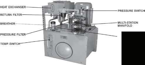
50 Parker Hannifin Corporation Hydraulic Pump and Power Systems Division Marysville, Ohio USA HY28-2661-CD/US Hydraulic Power Units V-Pak Low Profile Series Technical Information Accessory Options V-Pak LOW PROFILE TEMP/LEVEL SWITCH SEE MANIFOLD 4.5 GPM @ 1.750 RPM 4.5 GPM @ 1.750 RPM OPTIONS SEE COMPENSATOR OPTIONS EXAMPLE OF VARIOUS ACCESSORIES INSTALLED FOR REFERENCE ONLY TEMP/LEVEL SWITCH MULTI-STATION MANIFOLD PRESSURE SWITCH BREATHER RETURN FILTER TEMP. SWITCH PRESSURE FILTER HEAT EXCHANGER OPTION OPTION OPTION OPTION OPTION OPTION A B C E F A P T B PUMP CASE COOLING (7.5HP-25HP ONLY) PUMP CASE COOLING SYSTEM COOLING/FILTER LOOP RETURN LINE WATER/OIL HEAT EXCHANGER WATER TEMPERATURE MODULATING VALVE SCHEMATIC - BASIC UNIT WITH ACCESSORIES HYDRAULIC SCHEMATIC PRESSURE FILTER 2" COUPLING FOR C/S HEATER PUMP OUTLET CHECK VALVE BYPASS CHECK-RETURN HT. EX. ONLY RETURN FILTER-DUAL ELEMENT COMBINATION LEVEL/TEMPERATURE SWITCH H J K L N R* OPTION OPTION OPTION OPTION OPTION OPTION OPTION C H K M E N L F J M M M M
HY28-2661-CD/US Hydraulic Power Units
HY28-2661-CD/US Hydraulic Power Units
TechnicalInformation
VolumeControl LowProfilePowerUnits SeriesV-Paks
V-Pak Low Profile Series Catalog HY13-1552-002/US,EU
V-Pak Low Profile Series
Dimensions – Accessories V8 Reservoir with "Omit" Manifold Shown Inch equivalents for millimeters dimensions are shown in (**). Installation information is for reference only. Consult factory or visit Parker's Econfigurator for detailed information.
HEAT REMOVAL HEAT REMOVAL
OPTION A.6 KW (.80 HP*) 1.1 KW (1.5 HP*) OPTION B
*Performance data are based on 100SSU oil leaving the cooler 4°C (40°F) higher than the ambient air temperature used for cooling.
Technical Information 35
Parker Hannifin Corporation Hydraulic Pump and Power Systems Division Marysville, Ohio USA
Parker Hannifin Cor poration Hydraulic Pump Division Marysville, Ohio USA
Parker Hannifin Corporation HydraulicPumpDivision Marysville, Ohio USA 11
51
Option "A" Cooling Loop 5.6 KW - 18.6 KW (7.5 HP - 25 HP) ONLY Option "B" Cooling Loop
V-PAK T P
V-PAK T P
(3.38) 85.9 (5.11) 129.8
HY28-2661-CD/US
Technical Information
Technical Information
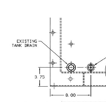
Dimensions – Accessories
V8 Reservoir with "Omit" Manifold Shown
Hydraulic Power Units
Hydraulic Power Units Profile Technical Information Catalog HY13-1552-002/US,EU Volume Control Low Profile Power Units Series V-Paks
V-Pak Low Profile Series
Inch equivalents for millimeters dimensions are shown in (**) Order ing Note: Units with PVP76 pumps and requiring options "A", "B" or "C" can only be ordered with V8 (302.8 L/80 Gal.) reservoir.
HEAT REMOVAL OPTION C 3.4 KW (4.5 HP*)
*Perfor mance data are based on 100SSU oil leaving the cooler 4°C (40°F) higher than the ambient air temperature used for cooling.
(16.35) 415.3
Option "C" System Cooling/Filter Loop
Parker Hannifin Corporation Hydraulic Pump Division Marysville, Ohio USA
Parker Hannifin Corporation Hydraulic Pump and Power Systems Division Marysville, Ohio USA
Parker Hannifin Cor poration Hydraulic Pump Division Marysville, Ohio USA
52
38
12
V-PAK PUMP PRIME
T
3/4"
INCLUDING WITH
HALF COUPLING
OPTION “C”
HY28-2661-CD/US
Hydraulic Power Units
HY28-2661-CD/US Hydraulic Power Units
V-Pak Low Profile Series Technical Information Catalog HY13-1552-002/US,EU
TechnicalInformation Dimensions–
Volume Control LowProfilePower Units SeriesV-Paks
V-Pak Low Profile Series Technical Information
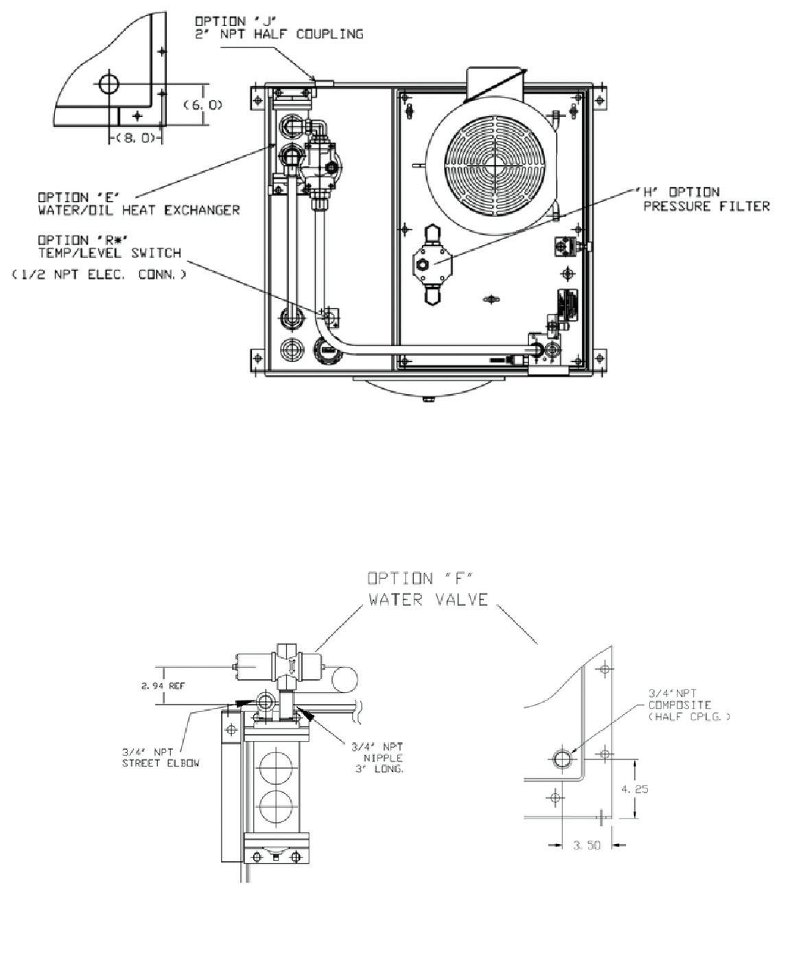
Parker Hannifin Corporation Hydraulic Pump and Power Systems Division Marysville, Ohio USA
Parker Hannifin Cor poration Hydraulic Pump Division Marysville, Ohio USA
53
37
13
Parker Hannifin Corporation HydraulicPump Division Marysville, Ohio USA
Accessories
Reservoir with E, F, H, J, N & R Options
equivalents for millimeters dimensions are shown
OPTION “E” 13.4KW (18HP) HEAT REMOVAL @ GPM OPTION “N” RETURN FILTER OPTION “F” WATER VALVE
V8
Shown Inch
in (**).
Dimensions Accessories
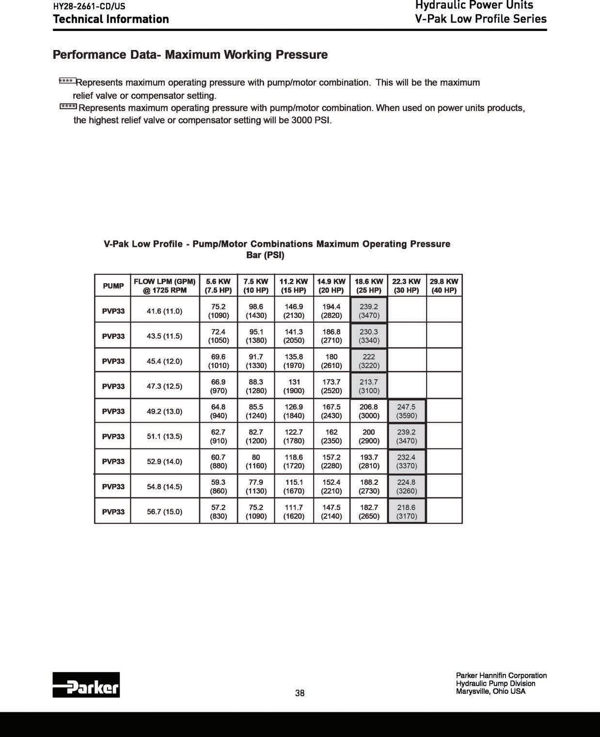
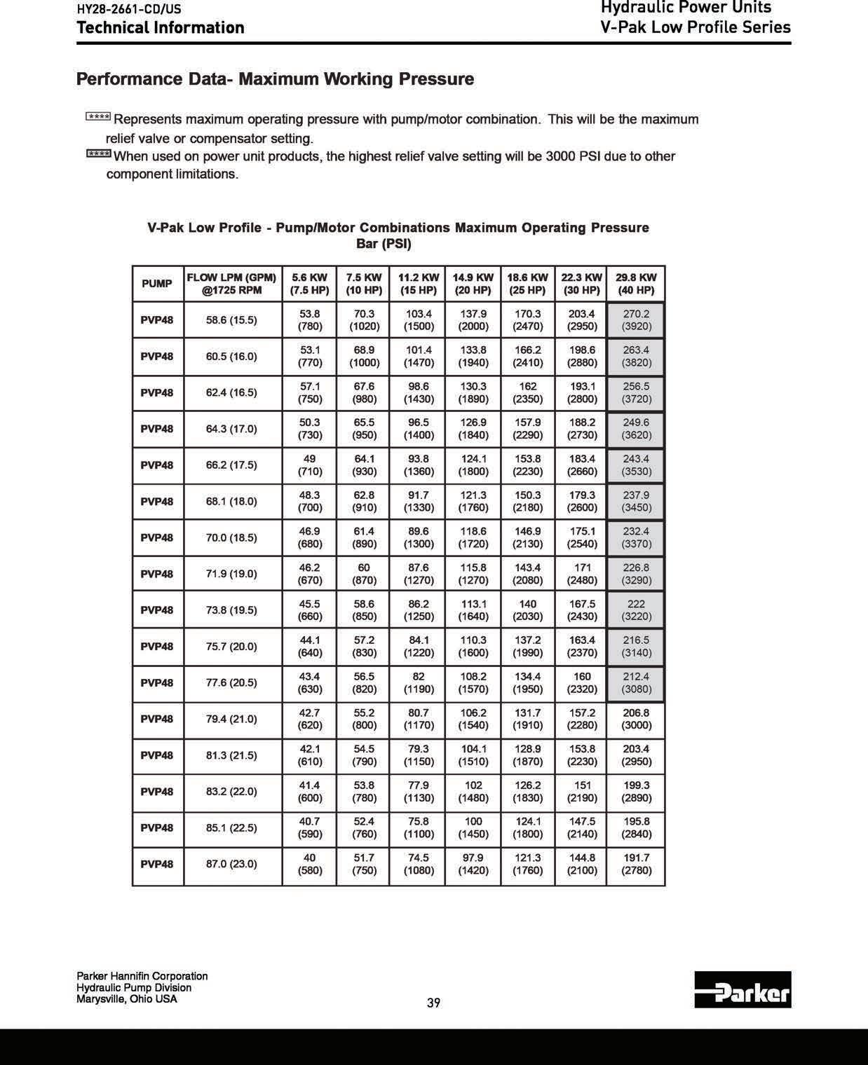
Perfomance Data — Maxiumum Working Pressure
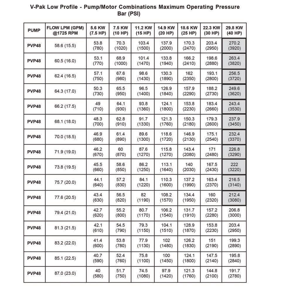
HY28-2661-CD/US Hydraulic Power Units
V-Pak Low Profile Series Technical Information
Performance Data- Maximum Working Pressure
Performance Data – Maximum Working Pressure
**** Represents maximum operating pressure with pump/motor combination. This will be the maximum relief valve or compensator setting.
**** Represents maximum operating pressure with pump/motor combination. When used on power unit products this will represent a 207 bar (3000 psi) relief valve or compensator setting.
V-Pak Low Profile - Pump/Motor Combinations Maximum Operating Pressure Bar (PSI)
PMUP )MPG(MPLWOLF MPR5271@ WK6.5 )PH5.7( WK5.7 )PH01( WK2.11 )PH51( WK9.41 )PH02( WK6.81 )PH52( WK3.22 )PH03( WK8.92 )PH04(
67PVP )0.42(8.09 7.02 )003( 7.13 )064( 2.55 )008( 6.87 )0411( 001 )0541( 3.121 )0671( 2.761 )5242(
67PVP )0.52(6.49 )092( )054( 4.35 )577( 8.57 )0011( 5.69 )0041( 2.711 )0071( 3.061 )5232(
67PVP )0.62(4.89 6.81 )072( 6.92 )034( 4.25 )067( 8.37 )0701( 5.49 )0731( 8.311 )0561( 8.551 )0622(
67PVP )0.72(2.201 9.71 )062( 3.92 )524( 3.05 )037( ) 0301( 4.19 )5231( 8.311 )0561( 8.551 )0622(
67PVP )0.82(0.601 6.71 )552( 6.72 )004( 3.84 )007( 3.86 )099( 3.88 )0821( 5.601 )5451( 1.441 )0902(
67PVP )0.92(8.901 2.71 )052( 9.62 )093( 5.64 )576( 5.56 )059( 9.68 )0621( 5.401 )5151( 7.041 )0402(
67PVP )0.03(6.3119.62 )093( 5.54 )066( 8.36 )529( 4.38 )0121( 4.301 )0051( 9.731 )0002(
67PVP )0.13(3.7119.52 )573( 8.34 )536( 4.16 )098( 7.08 )0711( 9.79 )0241( 4.231 )0291(
67PVP )0.23(1.1218.42 )063( 7.24 )026( 3.06 )578( 6.87 )0411( 1.59 )0831( 6.821 )5681(
67PVP )0.33(9.4214.32 )043( 4.14 )006( 9.75 )048( 8.57 )0011( 4.29 )0431( 8.421 )0481(
67PVP )0.43(7.8214.22 )523( 6.93 )575( 9.65 )528( 1.47 )5701( 3.09 )0131( 7.121 )5671(
67PVP )0.53(5.2314.12 )013( 5.63 )035( 2.55 )008( 7.07 )5201( 9.78 )5721( 9.811 )5271(
67PVP )0.63(7.6317.02 )003( 2.53 )015( 1.35 )077( 9.86 )0001( 8.48 )0321( 111 )0161(
56
Parker Hannifin Corporation Hydraulic Pump and Power Systems Division Marysville, Ohio USA
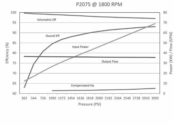
57
V-Pak Low Profle Performance Data Hydraulic Power Units V-Pak Low Profile Series Technical Information 41
Parker Hannifin Corporation Hydraulic Pump and Power Systems Division Marysville, Ohio USA HY28-2661-CD/US
Power V-Pak Profile Technical Information Catalog
VolumeControl LowProfilePowerUnits SeriesV-Paks
17 TechnicalInformation PerformanceData NOTE: [ ] 1714 WHERE: Q PSI CHp NOTE: Fluid Standard Hydraulics Oil 100 SSU @ 49°C (120°F) Flow, Horsepower and Efficiency Charts 8 10 12 14 16 18 20 100 90 80 70 60 50 Flow Efficiency% Power PVP33 @ 1800 RPM 0 4 2 6 30.3 37.9 45.4 53.0 60.6 68.2 75.7 0 15.1 7.6 22.7 0 0 Bar PSI 69 1000 138 2000 207 3000 275 4000 Pressure GPM LPM 0 6.0 11.9 17.9 23.9 29.8 0 8.0 16.0 24.0 32.0 40.0 HPKW Volumetric Efficiency Overall Efficiency Flow InputPoweratFullFlow Compensated Power 12 16 18 21 24 100 90 80 70 60 50 Flow Efficiency% Power PVP48 @ 1800 RPM 0 6 3 9 45.4 60.6 68.1 79.5 90.9 0 22.7 11.4 34.1 0 0 Bar PSI 69 1000 138 2000 207 3000 275 4000 Pressure GPMLPM 0 11.2 22.4 0 15.0 30.0 33.6 44.8 45.0 60.0 HPKW Flow Efficiency Compensated Power FullFlowPower
Low Profile Performance Data
Parker Hannifin Corporation Hydraulic Pump Division Marysville, Ohio USA
HY13-1552-002/US,EU
Parker Hannifin Corporation HydraulicPumpDivision Marysville, Ohio USA
V-Pak
HY28-2661-CD/US
Technical Information
V-Pak Low Profle Performance Data — Heat Exchangers

Hydraulic Power Units
V-Pak Low Profile Series
KW (HP) REMOVAL
RESERVOIR SIZE LITERS (GALLONS)
303 (80)
.89 (1.2)
Heat removal is based on static ambient air of 29°C (85°F) and max. oil temperature of 57°C (135°F).
Parker Hannifin Corporation Hydraulic Pump and Power Systems Division Marysville, Ohio USA
58
Additional Installation Information
HY28-2661-CD/US Catalog HY28-2661-CD/US
Operating Notes
Jog the electric motor once and verify that the electric motor is rotating in the same direction as the arrow on the electric motor housing. If direction is inco rrect, reverse two of the th ree leads on a 3-phase electric motor.
D & H-Pak power units are tested and relief valve is set at maximum pressure of the pump/ motor combination.
V-Pak power units are tested and pressure control valves are factory preset. If adjustments are needed, follow the procedure below: Begin adjusting relief valve and pump compensator cont rol valve to increase pressure gradually. (NOTE: Always set relief valve 250 PSI higher than pump compensato r pressure control valve or severe overheating will occur.)
If pump fails to prime, vent pump discharge to atmosphere to establish fluid flow.
Reservoir temperature should not exceed 66°C (150°F). System reliability and component service life will be r educed when system is operated at highe r temperature.
Clean fluid = improved system reliability and longer component service life, change filter element s whenever filter indicators indicate a dirty element condition
Volume Control Vertical Power Units
Hydraulic Power Units Series D, H, V-Packs
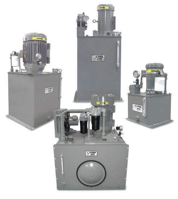
It is recommended that every 4,000 operating hours or once a year, whichever occurs first, the filler/ breather cap and suction strainer should be replaced
Fluid Recommendations
Premium quality hydraulic oil with a viscosity range between 150-250 SSU (30-50 cst.) at 100°F (38°C) Normal operating viscosity range between 80-1000 SSU (17-180 cst.). Maximum start-up viscosity is 4000 SSU (1000 cst.)
NOTE: Consult Parker when exceeding 160°F (71°C) ope r atio n. Oil should have maxim um an ti-wea r properties, rust and oxidation treatment
Filtration
For maximum pump and system component life, the system should be protected from contamination at a level not to exceed 125 particles greater than 10 microns per milliliter of fluid. (SAE Class 4 / ISO 16/13.) Due to the nature of variable displacement pumps, variations in pump inlet conditions, fluid acceleration losses, system aeration, and duty cycle must be carefully considered before specifying suction line filtration Contact your Parker representative for assistance
NOTE: For additional information refer to latest edition of Bulletin No. HY13-2600-550-xxx.
59
Parker Hannifin Corporation Hydraulic Pump and Power Systems Division Marysville, Ohio USA
28
Parker Hannifin Corporation Hydraulic Pump Division Mar yville, Ohio USA
Installation Information Series D, H, V-Paks
HY28-2661-CD/US Catalog HY28-2661-CD/US
Additional Technical Information
Technical Information
The totally enclosed pump mounting bracket offers precision shaft alignment and safety from the rotating shafts and coupling. The bracket is designed to mount on the motor face with the motor coupling half secure to the shaft. Then the pump, with its coupling half secure on the pump shaft, is mounted and the coupling halves are engaged. This will require proper spacing of the coupling prior to installation and a coupling with an outside diameter less than “P” dimension. If the coupling selected cannot be assembled this way, both coupling halves must be installed on the motor shaft. Next, mount the adapter on the motor. Then the pump can be mounted and the coupling secured to the pump by using the access slot to tighten the pump shaft coupling set screw.
Volume Control Vertical Power Units
Pump Mounting Adapters
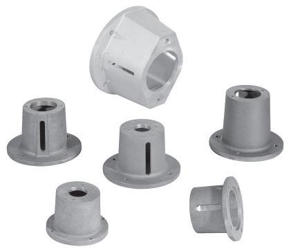
Hydraulic Power Units Pump Mounting Adapters
876631 SAE AA56C6.75.0 5.88N/A4.503.501.633/8-160.442.00YESYES13 lb. 876632 SAE AA 182TC/256TC9.05.3 7.25N/A8.505.001.633/8-160.562.00YESYES14 lb. 876633 SAE A56C6.75.0 5.88N/A4.504.252.103/8-160.443.25YESYES14 lb. 876634 SAE A 182TC/256TC9.05.3 7.25N/A8.505.002.103/8-160.563.25YESYES14 lb. 876635 SAE A 182TC/256TC9.05.3 7.25N/A8.505.882.103/8-160.563.25YESYES15 lb. 875343 SAE B 182TC/256TC 11.49.07.2510.258.505.752.881/2-130.534.00YESNO27 lb. 875344 SAE B 182TC/256TC 11.49.07.2510.258.506.812.881/2-130.534.00YESNO28 lb. 876683 SAE B 182TC/256TC9.08.8 7.25N/A8.506.382.881/2-130.534.00NOYES17 lb. 876684SAE C182TC/256TC9.09.37.25N/A8.506.693.565/8-110.535.00NOYES120 lb. * All dimensions are in inches.
NOTE: It is the responsibility of the user to check the listed dimensions to ensure suitability of mounting adapter with pump/coupling/motor combination.
Parker Hannifin Corporation Hydraulic Pump Division Maryville, Ohio USA
Parker Hannifin Corporation Hydraulic Pump and Power Systems Division Marysville, Ohio USA
60
29
ModelPumpMotor ABC1C2D Face to GHMP VerticalHorizontal StyleWeight NumberMounting Mounting Face MountingMounting
Dimensions* Pump Mounting Adapter M DIA THRU EQUALLY SPACED ON C1 DIA. B.C. (4 PLACES) H THREAD 2 PLACES ACCESS SLOT STYLE 1 ADAPTER (SEE CHART FOR MOUNTING ORIENTATION) STYLE 2 ADAPTER (VERTICAL MOUNT ONLY) 45 D DIA. A DIA. P DIA. G G M DIA THRU EQUALLY SPACED ON C2 DIA. B.C. (4 PLACES) M DIA THRU EQUALLY SPACED ON C1 DIA. B.C. (4 PLACES) H THREAD 2 PLACES 45 G G FACE TO FACE B DIA. FACE TO FACE (56C FRAME) ACCESS SLOT D DIA. A DIA. P DIA. FACE TO FACE B DIA.
HY28-2661-CD/US Catalog HY28-2661-CD/US
Conversion Equations
Application Formulas
•1 GPM at 1500 PSI = 1 HP (General Rule)
•1 Gallon = 231 Cubic Inches (3.7854 Liters)
•1 Gallon Oil = 7.08 Lbs.
•1 bar = 14.5 PSI
•25.4mm = 1 Inch
HP = GPM x PSI 1714 x Pump Efficiency
PSI = 1714 x Pump Efficiency x HP GPM
Volume Control Vertical Power Units
Conversion Equations
•1 HP = 42.4 BTU/Min.
•1 Gallon = 3.7854 Liters
Hydraulic Power Units D, H and V-Pak Series
GPM = 1714 x Pump Efficiency x HP PSI
HP = Torque (in.-lbs.) x RPM 63025
Torque = HP x 63025 RPM
RPM = HP x 63025 Torque
Motor Information
At 440V — 3-Phase Motor Draws 1.25 AMP/HP
At 220V — 3-Phase Motor Draws 2.5 AMP/HP
At 110V — Single Phase Motor Draws 10 AMP/HP
Parker Hannifin Corporation
Hydraulic Pump and Power Systems Division Marysville, Ohio USA
Parker Hannifin Corporation Hydraulic Pump Division Maryville, Ohio USA
61
30
HY28-2661-CD/US Notes Hydraulic Power Units
Parker Hannifin Corporation Hydraulic Pump and Power Systems Division Marysville, Ohio USA
62
HY28-2661-CD/US
Offer of Sale
The items described in this document and other documents and descriptions provided by Parker Hannifin Corporation, Hydraulics Group, and its authorized distributors (“Seller”) are hereby offered for sale at prices to be established by Seller. This offer and its acceptance by any customer (“Buyer”) shall be governed by all of the following Terms and Conditions. Buyer’s order for any item described in its document, when communicated to Seller verbally, or in writing, shall constitute acceptance of this offer. All goods or work described will be referred to as “Products”.
1. Terms and Conditions. Seller’s willingness to offer Products, or accept an order for Products, to or from Buyer is expressly conditioned on Buyer’s assent to these Terms and Conditions and to the terms and conditions found on-line at www.parker.com/ saleterms/. Seller objects to any contrary or additional term or condition of Buyer’s order or any other document issued by Buyer.
2. Price Adjustments; Payments. Prices stated on the reverse side or preceding pages of this document are valid for 30 days. After 30 days, Seller may change prices to reflect any increase in its costs resulting from state, federal or local legislation, price increases from its suppliers, or any change in the rate, charge, or classification of any carrier. The prices stated on the reverse or preceding pages of this document do not include any sales, use, or other taxes unless so stated specifically. Unless otherwise specified by Seller, all prices are F.O.B. Seller’s facility, and payment is due 30 days from the date of invoice. After 30 days, Buyer shall pay interest on any unpaid invoices at the rate of 1.5% per month or the maximum allowable rate under applicable law.
3. Delivery Dates; Title and Risk; Shipment. All delivery dates are approximate and Seller shall not be responsible for any damages resulting from any delay. Regardless of the manner of shipment, title to any products and risk of loss or damage shall pass to Buyer upon tender to the carrier at Seller’s facility (i.e., when it’s on the truck, it’s yours). Unless otherwise stated, Seller may exercise its judgment in choosing the carrier and means of delivery. No deferment of shipment at Buyers’ request beyond the respective dates indicated will be made except on terms that will indemnify, defend and hold Seller harmless against all loss and additional expense. Buyer shall be responsible for any additional shipping charges incurred by Seller due to Buyer’s changes in shipping, product specifications or in accordance with Section 13, herein.
4. Warranty. Seller warrants that the Products sold hereunder shall be free from defects in material or workmanship for a period of eighteen months from the date of delivery to Buyer. The prices charged for Seller’s products are based upon the exclusive limited warranty stated above, and upon the following disclaimer: DISCLAIMER OF WARRANTY: THIS WARRANTY COMPRISES THE SOLE AND ENTIRE WARRANTY PERTAINING TO PRODUCTS PROVIDED HEREUNDER. SELLER DISCLAIMS ALL OTHER WARRANTIES, EXPRESS AND IMPLIED, INCLUDING MERCHANTABILITY AND FITNESS FOR A PARTICULAR PURPOSE.
5. Claims; Commencement of Actions. Buyer shall promptly inspect all Products upon delivery. No claims for shortages will be allowed unless reported to the Seller within 10 days of delivery. No other claims against Seller will be allowed unless asserted in writing within 60 days after delivery or, in the case of an alleged breach of warranty, within 30 days after the date within the warranty period on which the defect is or should have been discovered by Buyer. Any action based upon breach of this agreement or upon any other claim arising out of this sale (other than an action by Seller for any amount due to Seller from Buyer) must be commenced within thirteen months from the date of tender of delivery by Seller or, for a cause of action based upon an alleged breach of warranty, within thirteen months from the date within the warranty period on which the defect is or should have been discovered by Buyer.
6. LIMITATION OF LIABILITY. UPON NOTIFICATION, SELLER WILL, AT ITS OPTION, REPAIR OR REPLACE A DEFECTIVE PRODUCT, OR REFUND THE PURCHASE PRICE. IN NO EVENT SHALL SELLER BE LIABLE TO BUYER FOR ANY SPECIAL, INDIRECT, INCIDENTAL OR CONSEQUENTIAL DAMAGES ARISING OUT OF, OR AS THE RESULT OF, THE SALE, DELIVERY, NON-DELIVERY, SERVICING, USE OR LOSS OF USE OF THE PRODUCTS OR ANY PART THEREOF, OR FOR ANY CHARGES OR EXPENSES OF ANY NATURE INCURRED WITHOUT SELLER’S WRITTEN CONSENT, EVEN IF SELLER HAS BEEN NEGLIGENT, WHETHER IN CONTRACT, TORT OR OTHER LEGAL THEORY. IN NO EVENT SHALL SELLER’S LIABILITY UNDER ANY CLAIM MADE BY BUYER EXCEED THE PURCHASE PRICE OF THE PRODUCTS.
7. Contingencies. Seller shall not be liable for any default or delay in performance if caused by circumstances beyond the reasonable control of Seller.
8. User Responsibility. The user, through its own analysis and testing, is solely responsible for making the final selection of the system and Product and assuring that all performance, endurance, maintenance, safety and warning requirements of the application are met. The user must analyze all aspects of the application and follow applicable industry standards and Product information. If Seller provides Product or system options, the user is responsible for determining that such data and specifications are suitable and sufficient for all applications and reasonably foreseeable uses of the Products or systems.
9. Loss to Buyer’s Property. Any designs, tools, patterns, materials, drawings, confidential information or equipment furnished by Buyer or any other items which become Buyer’s property, may be considered obsolete and may be destroyed by Seller after two consecutive years have elapsed without Buyer placing an order for the items which are manufactured using such property. Seller shall not be responsible for any loss or damage to such property while it is in Seller’s possession or control.
10. Special Tooling. A tooling charge may be imposed for any special tooling, including without limitation, dies, fixtures, molds and patterns, acquired to manufacture Products. Such special tooling shall be and remain Seller’s property notwithstanding payment of any charges by Buyer. In no event will Buyer acquire any interest in apparatus belonging to Seller which is utilized in the manufacture of the Products, even if such apparatus has been specially converted or adapted for such manufacture and notwithstanding any charges paid by Buyer. Unless otherwise agreed, Seller shall have the right to alter, discard or otherwise dispose of any special tooling or other property in its sole discretion at any time.
Parker Hannifin Corporation Hydraulic Pump and Power Systems Division Marysville, Ohio USA
63
11. Buyer’s Obligation; Rights of Seller. To secure payment of all sums due or otherwise, Seller shall retain a security interest in the goods delivered and this agreement shall be deemed a Security Agreement under the Uniform Commercial Code. Buyer authorizes Seller as its attorney to execute and file on Buyer’s behalf all documents Seller deems necessary to perfect its security interest. Seller shall have a security interest in, and lien upon, any property of Buyer in Seller’s possession as security for the payment of any amounts owed to Seller by Buyer.
12. Improper Use and Indemnity. Buyer shall indemnify, defend, and hold Seller harmless from any claim, liability, damages, lawsuits, and costs (including attorney fees), whether for personal injury, property damage, patent, trademark or copyright infringement or any other claim, brought by or incurred by Buyer, Buyer’s employees, or any other person, arising out of: (a) improper selection, improper application or other misuse of Products purchased by Buyer from Seller; (b) any act or omission, negligent or otherwise, of Buyer; (c) Seller’s use of patterns, plans, drawings, or specifications furnished by Buyer to manufacture Product; or (d) Buyer’s failure to comply with these terms and conditions. Seller shall not indemnify Buyer under any circumstance except as otherwise provided.
13. Cancellations and Changes. Orders shall not be subject to cancellation or change by Buyer for any reason, except with Seller’s written consent and upon terms that will indemnify, defend and hold Seller harmless against all direct, incidental and consequential loss or damage. Seller may change product features, specifications, designs and availability with notice to Buyer.
14. Limitation on Assignment. Buyer may not assign its rights or obligations under this agreement without the prior written consent of Seller.
15. Entire Agreement. This agreement contains the entire agreement between the Buyer and Seller and constitutes the final, complete and exclusive expression of the terms of the agreement. All prior or contemporaneous written or oral agreements or negotiations with respect to the subject matter are herein merged.
16. Waiver and Severability. Failure to enforce any provision of this agreement will not waive that provision nor will any such failure prejudice Seller’s right to enforce that provision in the future. Invalidation of any provision of this agreement by legislation or other rule of law shall not invalidate any other provision herein. The remaining provisions of this agreement will remain in full force and effect.
17. Termination. This agreement may be terminated by Seller for any reason and at any time by giving Buyer thirty (30) days written notice of termination. In addition, Seller may by written notice immediately terminate this agreement for the following: (a) Buyer commits a breach of any provision of this agreement (b) the appointment of a trustee, receiver or custodian for all or any part of Buyer’s property (c) the filing of a petition for relief in bankruptcy of the other Party on its own behalf, or by a third party (d) an assignment for the benefit of creditors, or (e) the dissolution or liquidation of the Buyer. 18. Governing Law. This agreement and the sale and delivery of all Products hereunder shall be deemed to have taken place in and shall be governed and construed in accordance with the laws of the State of Ohio, as applicable to contracts executed and wholly performed therein and without regard to conflicts of laws principles. Buyer irrevocably agrees and consents to the exclusive jurisdiction and venue of the courts of Cuyahoga County, Ohio with respect to any dispute, controversy or claim arising out of or relating to this agreement. Disputes between the parties shall not be settled by arbitration unless, after a dispute has arisen, both parties expressly agree in writing to arbitrate the dispute.
19. Indemnity for Infringement of Intellectual Property Rights. Seller shall have no liability for infringement of any patents, trademarks, copyrights, trade dress, trade secrets or similar rights except as provided in this Section. Seller will defend and indemnify Buyer against allegations of infringement of U.S. patents, U.S. trademarks, copyrights, trade dress and trade secrets (“Intellectual Property Rights”). Seller will defend at its expense and will pay the cost of any settlement or damages awarded in an action brought against Buyer based on an allegation that a Product sold pursuant to this Agreement infringes the Intellectual Property Rights of a third party. Seller’s obligation to defend and indemnify Buyer is contingent on Buyer notifying Seller within ten (10) days after Buyer becomes aware of such allegations of infringement, and Seller having sole control over the defense of any allegations or actions including all negotiations for settlement or compromise. If a Product is subject to a claim that it infringes the Intellectual Property Rights of a third party, Seller may, at its sole expense and option, procure for Buyer the right to continue using the Product, replace or modify the Product so as to make it noninfringing, or offer to accept return of the Product and return the purchase price less a reasonable allowance for depreciation. Notwithstanding the foregoing, Seller shall have no liability for claims of infringement based on information provided by Buyer, or directed to Products delivered hereunder for which the designs are specified in whole or part by Buyer, or infringements resulting from the modification, combination or use in a system of any Product sold hereunder. The foregoing provisions of this Section shall constitute Seller’s sole and exclusive liability and Buyer’s sole and exclusive remedy for infringement of Intellectual Property Rights.
20. Taxes. Unless otherwise indicated, all prices and charges are exclusive of excise, sales, use, property, occupational or like taxes which may be imposed by any taxing authority upon the manufacture, sale or delivery of Products.
21. Equal Opportunity Clause. For the performance of government contracts and where dollar value of the Products exceed $10,000, the equal employment opportunity clauses in Executive Order 11246, VEVRAA, and 41 C.F.R. §§ 60-1.4(a), 60-741.5(a), and 60-250.4, are hereby incorporated.
North America
Industrial USA Chicago Region Naperville, IL Tel: (630) 964 0796
Great Lakes Region Fairlawn, OH Tel: (330) 670 2680
Northeast Region Lebanon, NJ Tel: (908) 236 4121
Pacific Region Buena Park, CA Tel: (714) 228 2509 Southern Region Alpharetta, GA Tel: (770) 619 9767
Canada Milton, Ontario Tel: (905) 693 3000 México Toluca, Edo. de México Tel: (52) 72 2275 4200
Mobile USA Global Mobile Lincolnshire, IL Tel: (847) 821 1500 Central Region Lincolnshire, IL Tel: (847) 821 1500
Eastern Region North Canton, OH Tel: (330) 284 3355
Midwest Region Hiawatha, IA Tel: (319) 393 1221 Southern Region Aledo, TX Tel: (817) 441 1794
Western Region Buena Park, CA Tel: (714) 228 2509
Canada Milton, Ontario Tel: (905) 693 3000
México Apodaca, N.L. Tel: (52) 81 8156 6000
Truck USA
Eastern Region Cleveland, OH Tel: (440) 519 1125
Western Region San Ramon, CA Tel: (925) 735 9573
Canada Milton, Ontario Tel: (905) 693 3000
México Apodaca, N.L. Tel: (52) 81 8156 6000
Europe
Austria Wiener Neustadt Tel: (43) 2622 23501 0
Belgium Nivelles Tel: (32) 67 280 900
Czech Republic and Slovakia Klecany Tel: (420) 284 083 111 Denmark Ballerup Tel: (45) 4356 0400 Finland Vantaa Tel: (358) 20 753 2500 France Contamine-sur-Arve Tel: (33) 4 50 25 80 25
Germany Kaarst Tel: (49) 2131 4016 0 Greece Athens Tel: (30) 210 933 6450
Hungary Budapest Tel: (36) 1 220 4155 Ireland County Dublin, Baldonnell Tel: (353) 1 466 6370 Italy Corsico, Milano
Tel: (39) 02 45 19 21
The Netherlands Oldenzaal Tel: (31) 541 585000 Norway Ski Tel: (47) 64 91 10 00 Poland Warsaw Tel: (48) 22 57 32400
Portugal Leca da Palmeira Tel: (351) 22 999 7360
Romania Bucharest Tel: (40) 21 252 1382
Russia Moscow Tel: (7) 495 580 9145 Slovenia Novo Mesto Tel: (386) 7 337 6650 Spain Madrid Tel: (34) 91 675 7300 Sweden Spanga Tel: (46) 8 597 95000 Ukraine Kiev Tel: (380) 44 494 2731 United Kingdom Warwick, Tel: (44) 1926 317878
Asia Pacific Australia Castle Hill Tel: (61) 2 9634 7777 China Beijing Tel: (86) 10 6561 0520 Shanghai Tel: (86) 21 5031 2525 Hong Kong Tel: (852) 2428 8008 India Mahape, Navi Mumbai
Tel: (91) 22 5613 7081
Korea Seoul Tel: (82) 2 559 0400
Malaysia Subang Jaya Tel: (60) 3 5638 1476 New Zealand Mt. Wellington Tel: (64) 9 574 1744
Japan Tokyo Tel: (81) 3 6408 3900
Singapore Jurong Town Tel: (65) 6 887 6300 Taiwan Taipei Tel: (886) 2 2298 8987 Thailand Bangkok Tel: (662) 717 8140
Middle East United Arab Emirates Abu Dhabi Tel: (971) 2 678 8587
Latin America Pan American Division Miami, FL Tel: (305) 470 8800 Argentina Buenos Aires Tel: (54) 33 2744 4129 Brazil Cachoeirinha RS Tel: (55) 51 3470 9144 Venezuela Caracas Tel: (58) 212 238 5422
Africa
South Africa Kempton Park Tel: (27) 11 961 0700
Parker Hannifn Corporation
Hydraulic Pump and Power Systems Division 14249 Industrial Parkway Marysville, OH 43040 USA phone 937 644 4435 fax 937 642 3639 www.parker.com/hps
HY28-2661-CD/US Supercedes All Previous Versions 04/2016
©
2016
Parker Hannifn Corporation, all rights reserved

