Maintenance and Installation
Bladder Accumulators EBV
Accumulateurs à vessie EBV
Blasenspeicher Serie EBV


Accumulatore a sacca EBV


Bladder Accumulators EBV
Accumulateurs à vessie EBV
Blasenspeicher Serie EBV
Accumulatore a sacca EBV
Démontage/Remontage
Vous vous apprêtez à intervenir sur un accumulateur Parker Olaer destiné à contenir des fluides sous pression. Assurez-vous que l’accumulateur est conforme à la réglementation en vigueur dans le pays d’utilisation et que vous disposez:
- des documents délivrés avec l’accumulateur
- du matériel nécessaire à la maintenance des accumulateurs. En cas de difficulté, contacter impérativement Parker Olaer. Toute action improvisée peut être la source d’un danger potentiel. Le montage et démontage ne doivent être confiés qu’à des techniciens qualifiés (s’adresser à Parker Olaer ou à son réseau agréé).
DEMONTAGE DES ACCUMULATEURS
Avant de déposer l’accumulateur du circuit hydraulique, il faut impérativement relâcher la pression hydraulique du circuit et s’assurer de l’absence de pression hydraulique résiduelle au niveau de l’accumulateur.
A. Isoler l’accumulateur et décomprimer le circuit hydraulique à l’aide du bloc de décompression et d’isolement DI Parker Olaer ou décomprimer le circuit hydraulique.
B. Déposer l’accumulateur, le fixer horizontalement dans un étau ou tout autre système de fixation en protégeant le corps afin de ne pas l’endommager. Délimiter une zone de sécurité hors de l’alignement des ouvertures (côté hydraulique et azote) : attention au risque d’éjection de pièces pouvant survenir en cas de rupture des composants.
C. Dévisser le bouchon protecteur de la valve de gonflage (photo 1).
D. Dévisser le bouchon de la valve de gonflage (photo 2)
E. Evacuer le gaz contenu dans la vessie à l’aide d’un vérificateur gonfleur équipé d’un manomètre adapté à la pression de l’accumulateur jusqu’à ce qu’il indique une pression 0 (photo 3). S’assurer que la vessie n’est plus en pression d’azote en vérifiant qu’elle n’est plus en contact avec la douille, qui doit pouvoir bouger légèrement dans son logement.
IMPORTANT !
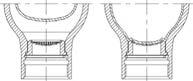
Si la vessie reste en appui sur la douille (voir schéma), cela signifie qu’il y a une pression résiduelle. Dans ce cas :
- stopper toute opération
- sécuriser la zone
- contacter immédiatement Parker Olaer
F. Retirer la valve de gonflage monobloc (photo 4) ou le mécanisme de valve intégrée ou l’obus de valve (photo 5A/photo 5B) suivant modèles.
G. Retirer l’écrou de fixation du corps de valve ainsi que la plaque firme (photo 6 et 7). En appuyant sur le corps de valve, repousser manuellement la vessie à l’intérieur du corps. Il ne doit pas y avoir de résistance.
IMPORTANT !
S’il est impossible de repousser la vessie à l’intérieur , cela signifie qu’il y a une pression résiduelle. Dans ce cas :
- stopper toute opération
- sécuriser la zone
- contacter immédiatement Parker Olaer
H. Suivant modèle, déposer la vis de purge hydraulique et son joint “vue éclatée” page 4.
I. Retirer le jonc d’arrêt (photo 8).
J. Retirer la douille perforée (photo 9).
K. Extraire la vessie par l’ouverture côté bouche en veillant à ne pas l’endommager (photo 10).
Nettoyer soigneusement toutes les pièces métalliques de l’accumulateur avec un solvant organique. Vérifier visuellement l’état des pièces montées (douille perforée, corrosion, sertissage et soudure de la grille). Vérifier qu’il n’y ait aucune trace de corrosion, ni de corps étrangers à l’intérieur
du corps de l’accumulateur. Dans le cas où le corps de l’accumulateur est protégé intérieurement, vérifier le bon état de la protection. Remplacer les pièces jugées défectueuses. Les joints, le jonc d’arrêt doivent être obligatoirement changés (voir vue éclatée page 4). Nettoyer la vessie avec un fluide compatible avec la nature du caoutchouc, (alcool isopropylique,par exemple). Vérifier que la vessie ne présente aucun défaut d’aspect. Pour toute inspection règlementaire, se référer à la réglementation en vigueur.
REMONTAGE DES ACCUMULATEURS
L. Evacuer l’air de la vessie en la comprimant (photo11).
M. Lubrifier abondamment l’intérieur du corps de l’accumulateur avec soit le fluide utilisé dans le circuit ou un produit similaire (environ 10% du volume de l’accumulateur pour capacité jusqu’à 5 litres ou 5% pour capacité supérieure) en le faisant tourner autour de son axe. Dans le cas d’un fluide à faible viscosité (inférieur à 5 CSt), consulter Parker Olaer.
N. Lubrifier la vessie puis l’introduire dans le corps de l’accumulateur (photo12). Contrôler que la vessie n’est pas pliée ou vrillée. Dans le cas d’accumulateur de grandes capacités, utiliser l’outillage approprié (tire-vessie).
O. Remonter la plaque firme et l’écrou de fixation sans bloquer ce dernier. (photo 13)
P. Introduire la douille perforée jusqu’à la mettre en butée dans le corps de l’accumulateur (photo 14).
Q. Monter impérativement un jonc neuf en veillant particulièrement à sa bonne mise en place dans la gorge prévue à cet effet (photo 15).
R. Suivant modèle, remonter précautionneusement la vis de purge avec son joint neuf, en veillant à bien l’engager.
S. Côté azote, visser l’écrou du corps de valve en maintenant celui-ci par les méplats appropriés (photo 16). Il est impératif que le corps de valve ne tourne pas.
T. Mettre en place la valve de gonflage monobloc au couple de 1.5 mdaN ou la valve intégrée au couple de 0.3 mdaN ou l’obus de valve suivant au couple de 0.03 mdaN (photo 17).
U. IMPERATIVEMENT ET POUR DES RAISONS DE SECURITE: Visser côté fluide un raccord non percé, qui doit rester présent pendant toute l’opération de gonflage.
V. Le montage d’un détendeur entre la bouteille d’azote et le vérificateur gonfleur est obligatoire
W. Avant de gonfler à l’azote l’accumulateur, faire tourner autour de son axe le corps de l’accumulateur afin d’obtenir une parfaite lubrification de toute la paroi interne de celui-ci.
Rappel : Utiliser uniquement de l’azote pur ≥ 99,8%. Il est formellement interdit de gonfler l’accumulateur avec tout autre fluide que l’azote. RISQUE D’EXPLOSION !
Immédiatement après effectuer lentement l’expansion de la vessie sous une pression d’azote de 1 à 1.5 bar (accumulateur en position horizontale : cf.tableau processus de gonflage).
Pour le gonflage de l’accumulateur et la mise en service, se conformer à la notice d’instructions.
RAPPEL : la pression de gonflage pour les accumulateurs basse pression ne doit jamais excéder 20 Bar à la température maxi d’utilisation. Pour une pression d’utilisation inférieure à 20 Bar, gonfler jusqu’à la pression indiquée sur la plaque firme.
Enfin vous assurer que les avertissements de sécurité initiaux (plaque firme, étiquette de gonflage, informations sécurité…) sont toujours lisibles. Si ce n’est pas le cas, consulter Parker Olaer pour fourniture.
Parker Hannifin Accumulator and Cooler Division EuropeWICHTIG! Sie sind im Begriff, Arbeiten an einem Parker Olaer Blasenspeicher auszuführen, der druckbeaufschlagte Fluide enthält. Vergewissern Sie sich, dass der Speicher den im Land seines Betriebs geltenden Vorschriften entspricht und dass Sie über folgendes verfügen: - die mit dem Speicher mitgelieferten schriftlichen Unterlagen, - das zur Wartung des Speichers erforderliche Material. Bei Auftreten von Problemen, kontaktieren Sie unbedingt Parker Olaer. Improvisierte Vorgehensweisen stellen eine potentielle Gefahrenquelle dar. Montage und Demontage dürfen nur von qualifiziertem Fachpersonal ausgeführt werden (wenden Sie sich an Parker Olaer oder eine unserer befugten Vertretungen).
DEMONTAGE DES SPEICHERS
Vor dem Ausbau eines Speichers aus dem Hydrauliknetz ist unbedingt der Hydraulikdruck des betroffenen Kreislaufs abzulassen und sich zu vergewissern, dass im Speicher kein Restdruck vorhanden ist.
A. Unter Einsatz eines Sicherheits- und Absperrblocks DI Parker Olaer den Speicher vom Hydraulikkreislauf trennen und den Druck aus dem Kreislauf ablassen oder das Hydrauliksystem drucklos machen.
B. Den Speicher ausbauen, ihn horizontal in einem Schraubstock oder einem anderen Halterungssystem befestigen, wobei der Speicherkörper vor Beschädigungen zu schützen ist. Grenzen Sie vor den Öffnungen einen Sicherheitsbereich ab (hydraulik- und stickstoffseitig). Achten Sie hierbei darauf, dass bei Beschädigungen von Komponenten Teile umherfliegen könnten.
C. Die Schutzkappe des Gasventils abschrauben (Foto 1).
D. Die Hutmutter des Gasventils abschrauben (Foto 2).
E. Das in der Blase befindliche Gas mit Hilfe eines Prüf- und Füllgeräts ablassen, das mit einem dem Fülldruck des Speichers angemessenen Manometer ausgestattet ist, bis dieses einen Druck von 0 anzeigt (Foto 3). Sich vergewissern, dass der Stickstoff in der Speicherblase keinen Überdruck mehr aufweist, indem überprüft wird, dass die Blase nicht mehr mit dem Speicherkörper in Kontakt ist, sie muss sich etwas im Speicherkörper bewegen können.
WICHTIG!
Wenn die Blase gegen die Speicherkörperwand gedrückt bleibt (siehe Schema), bedeutet dies, dass noch Überdruck vorhanden ist.
In diesem Falle:
- die Arbeiten stoppen
- den Arbeitsbereich sichern
- sofort Parker Olaer kontaktieren
F. Je nach Modell das Monoblock-Gasventil (Foto 4) oder den integrierten Ventilmechanismus oder den Ventileinsatz (Foto 5A/Foto 5B) abnehmen.
G. Die Haltemutter des Ventilkörpers sowie das Firmenschild abnehmen (Fotos 6 und 7). Die Speicherblase per Hand nach innen in den Speicherkörper schieben, wobei auf den Ventilkörper gedrückt wird. Es darf kein Widerstand zu spüren sein
WICHTIG!
Wenn es nicht möglich ist, die Speicherblase nach innen zu schieben bedeutet dies, dass noch Überdruck vorliegt. In diesem Fall:
- die Arbeiten stoppen
- den Arbeitsbereich sichern
- sofort Parker Olaer kontaktieren
H. Je nach Modell die Flüssigkeits-Ablassschraube und ihre Dichtung abnehmen, siehe Detaildarstellung Seite 4.
I. Den Spannring abnehmen (Foto 8).
J. Den Siebeinsatz herausnehmen (Foto 9).
K. Die Speicherblase vorsichtig durch die Flüssigkeitsöffnung herausziehen, dabei darauf achten, dass sie nicht beschädigt wird (Foto 10).
REINIGUNG UND INSPEKTION
Alle Metallteile des Blasenspeichers mit einem organischen Lösungsmittel sorgfältig reinigen. Den Zustand der montierten Bauelemente sichtprüfen (Siebeinsatz, Korrosion, Pressverbindungen und Schweißnähte des Siebeinsatzes). Sicherstellen ,dass keinerlei Rost oder Verschmutzungen im Inneren des Speicherkörpers auffindbar sind. Wenn der Speicherkörper einen
Innenschutz aufweist, diesen auf seinen guten Zustand überprüfen. Als defekt erkannte Teile austauschen. Die Dichtungen und der Spannring sind in jedem Fall zu wechseln (siehe Detaildarstellung Seite 4). Die Speicherblase mit einer für die Gummiart geeigneten Flüssigkeit reinigen (z. B. Isopropylalkohol). Sich vergewissern, dass die Speicherblase keinerlei Oberflächenfehler aufweist. Bei vorschriftsmäßigen Inspektionen sind die jeweils geltenden Vorschriften zu beachten.
MONTAGE DES SPEICHERS
L. Die Luft aus der Speicherblase entfernen, indem sie zusammengedrückt wird (Foto 11).
M. Das Innere des Speicherkörpers mit der im Kreislauf verwendeten Flüssigkeit oder einem ähnlichen Medium reichlich schmieren, indem er um seine eigene Achse gedreht wird (ca. 10% des Speichervolumens bei Kapazitäten von bis zu 5 Litern und 5% des Speichervolumens bei darüberliegenden Kapazitäten).
Bei Flüssigkeiten mit geringer Viskosität (weniger als 5 cSt) mit Parker Olaer Kontakt aufnehmen.
N. Die Speicherblase schmieren und in den Speicherkörper einführen (Foto 12). Darauf achten, dass die Speicherblase weder Falten noch Verdrehungen bildet. Bei Blasenspeichern mit großen Kapazitäten sind geeignete Hilfsmittel zu verwenden (Blasenzieher).
O. Das Firmenschild und die Haltemutter wieder anbringen, ohne letztere festzuziehen (Foto 13).
P. Den Siebeinsatz bis zum Anschlag in die Speicherkörperöffnung einführen (Foto 14).
Q. Unbedingt einen neuen Spannring einsetzen und seinen ordnungsgemäßen Sitz in der dafür vorgesehenen Nut prüfen (Foto 15).
R. Je nach Modell vorsichtig die Ablassschraube mit ihrer neuen Dichtung wieder anbringen, wobei darauf zu achten ist, dass sie ordnungsgemäß positioniert wird.
S. Stickstoffseitig die Mutter des Ventilkörpers aufschrauben, wobei letzterer an den dafür vorgesehenen Abflachungen gehalten wird (Foto 16). Der Ventilkörper darf sich nicht drehen.
T. Das Monoblock-Gasfüllventil anbringen mit einem Anzugsmoment von 1.5 mdaN oder integrierte Gasfüllventil von 0.3 mdaN oder den Ventileinsatz anbringen und mit einem Anzugsmoment von 0.03 mdaN (Foto 17).
U. AUS SICHERHEITSGRÜNDEN UNBEDINGT NOTWENDIG: Flüssigkeitsseitig ist eine Blindkupplung anzuschrauben, die während dem gesamten Vorfüllvorgang dort verbleiben muss.
V. Zwischen der Stickstoffflasche und dem Prüf- und Füllgerät ist unbedingt ein Druckminderer anzubringen.
W. Vor dem Vorfüllen des Speichers mit Stickstoff ist der Speicherkörper um seine eigene Achse zu drehen, um eine perfekte Schmierung der gesamten Innenflächen zu erreichen.
Hinweis: Es ist nur Stickstoff in einer Reinheit von mindestens ≥99,8. Es ist strengstens untersagt, die Speicherblase mit einem anderen Gas als Stickstoff zu befüllen. EXPLOSIONSGEFAHR!
Sofort nach der Ausführung dieser Maßnahme ist die Speicherblase langsam mit einem Stickstoffdruck von 1 bis 1,5 bar vorzufüllen (Speicher in horizontaler Lage: siehe Füll-Tabelle).
Zum Vorfüllen des Speichers und zur Inbetriebnahme die Gebrauchsanweisung heranziehen.
HINWEIS: Der Vorfülldruck für Niederdruck-Blasenspeicher darf in keinem Fall 20 bar bei maximaler Betriebstemperatur überschreiten. Bei Betriebsüberdrücken von unter 20 bar bis zum auf dem Firmenschild angegebenen Druck befüllen.
Sich davon vergewissern, dass die ursprünglichen Warnhinweise (Firmenschild, Fülletikett, Sicherheitshinweise usw.) weiterhin lesbar sind. Wenn dies nicht der Fall ist, bitte mit Parker Olaer Kontakt aufnehmen, um Ersatz zu erhalten.
Parker Hannifin
Accumulator and Cooler Division Europe
Smontaggio/Rimontaggio
State per intervenire su un accumulatore destinato a contenere dei fluidi sotto pressione. Accertatevi che l’accumulatore sia conforme alla regolamentazione in vigore nel paese d’utilizzo e e di avere a disposizione:
• i documenti consegnati con l’accumulatore.
• il materiale necessario alla manutenzione degli accumulatori. In caso di problemi, contattare tassativamente Parker Olaer. Ogni azione improvvisata può essere fonte di un potenziale pericolo. Il montaggio e lo smontaggio devono essere affidati esclusivamente a tecnici qualificati (rivolgersi a Parker Olaer o alla sua rete di distribuzione autorizzata).
SMONTAGGIO DEGLI ACCUMULATORI
Prima di staccare l’accumulatore dal circuito idraulico bisogna tassativamente scaricare la pressione idraulica del circuito e assicurarsi che non vi sia pressione idraulica residua a livello dell’accumulatore.
A. Isolare l’accumulatore e decomprimere il circuito idraulico utilizzando il blocco di decompressione e isolamento DI Parker Olaer o decomprimere in altro modo il circuito idraulico.
B. Staccare l’accumulatore, fissarlo orizzontalmente in una morsa o con un qualsiasi altro sistema di fissaggio, proteggendo il corpo dell’accumulatore per non danneggiarlo. Delimitare una zona di sicurezza al di fuori dall’area di allineamento delle aperture (lato impianto idraulico e azoto): fare attenzione al rischio di espulsione di pezzi che può sopraggiungere in caso di rottura di componenti.
C. Svitare il tappo di protezione della valvola di gonfiaggio (foto 1).
D. Svitare il tappo della valvola di gonfiaggio (foto 2).
E. Evacuare il gas contenuto nella sacca con l’ausilio del verificatore gonfiatore, dotato di un manometro adatto alla pressione dell’accumulatore, fintanto che il manometro non indichi una pressione pari a 0 (foto 3). Accertarsi che la sacca non sia più sotto pressione di azoto verificando che non sia più a contatto con la succhieruola, deve muoversi all’interno del sua sede.
IMPORTANTE !
Se la sacca resta appoggiata sulla succhieruola (vedere lo schema), questo significa che esiste una pressione residua. In questo caso:
- arrestare qualsiasi operazione
- mettere in sicurezza la zona
- contattare immediatamente Parker Olaer
F. Rimuovere la valvola di gonfiaggio monoblocco (foto 4) o la valvola integrata o l’anima della valvola (foto 5), in base ai modelli.
G. Rimuovere il dado di fissaggio dal corpo della valvola e la targhetta aziendale (foto 6 e 7).
Premendo sul corpo della valvola spingere manualmente la sacca all’interno del corpo. Non si deve incontrare resistenza.
IMPORTANTE !
Se non è possibile spingere la sacca all’interno, questo significa che esiste una pressione residua. In questo caso,
- arrestare qualsiasi operazione
- mettere in sicurezza la zona
- contattare immediatamente Parker Olaer
H. In base al modello, staccare la vite di spurgo idraulico e il suo giunto (vedere vista esplosa).
I. Rimuovere l’anello a scatto elastico (foto 8).
J. Rimuovere la boccola perforata (foto 9).
K. Estrarre la sacca attraverso l’apertura lato bocca, prestando attenzione a non danneggiarla (foto 10).
PULIZIA E ISPEZIONE
Pulire accuratamente tutti i pezzi metallici dell’accumulatore con un solvente organico. Verificare a vista lo stato dei pezzi (succhieruola, corrosione, aggraffatura e saldatura della griglia).
Pulire la sacca con un fluido compatibile con la natura della gomma (ad esempio alcol isopropilico).
Verificare che la sacca non presenti .alcuna anomalia come aspetto. Verificare che non ci sia alcun segno di corrosione e che non vi siano corpi estranei all’interno del corpo dell’accumulatore.
Nel caso in cui il corpo dell’accumulatore sia protetto interiormente, verificare le buone condizioni della protezione. Per tutte le ispezioni regolamentari, fare riferimento alla normativa in vigore. Sostituire i pezzi giudicati difettosi. I giunti e l’anello a scatto elastico devono essere obbligatoriamente sostituiti (vedere vista esplosa).
RIMONTAGGIO DEGLI ACCUMULATORI
L. Evacuare l’aria dalla sacca comprimendola (foto11).
M. Lubrificare abbondantemente l’interno del corpo dell’accumulatore o con il fluido utilizzato nel circuito o con un prodotto simile (circa il 10% del volume dell’accumulatore per una capacità fino a 5 litri o il 5% per una capacità superiore), facendolo girare attorno al proprio asse. Nel caso di un fluido a bassa viscosità (inferiore a 5 CSt - centiStoke), consultare Parker Olaer.
N. Lubrificare la sacca e poi introdurla nel corpo dell’accumulatore (foto 12). Controllare che la sacca non sia piegata o attorcigliata. Nel caso di un accumulatore di grande capacità, utilizzare l’utensile idoneo (tira-sacca).
O. Rimontare la targhetta aziendale e il dado di fissaggio senza bloccare quest’ultimo (foto 13).
P. Introdurre la boccola perforata fino all’arresto nel corpo dell’accumulatore (foto 14).
Q. Montare tassativamente un anello a scatto elastico nuovo prestando particolare attenzione al corretto posizionamento nella gola prevista allo scopo (foto 15).
R. In base al modello, rimontare con cautela la vite di spurgo e il suo giunto nuovo, prestando attenzione a inserirla correttamente.
S. Sul lato azoto, avvitare il dado del corpo della valvola mantenendolo mediante le apposite superfici piane e poi serrarlo (foto 16). Il corpo della valvola non deve assolutamente girare.
T. Installare la valvola di gonfiaggio monoblocco con una coppia di 1.5 mdaN (metri decaNewton), la valvola integrata con una coppia di 0.3 mdaN o l’anima della valvola con la coppia di 0,03 mdaN (foto 17).
U. Tassativamente e per ragioni di sicurezza: Avvitare lato fluido un raccordo o una flangia che deve rimanere presente per tutta l’operazione di gonfiaggio.
V. Sul lato azoto, è obbligatorio il montaggio di un riduttore di pressione tra la bombola e il verificatore gonfiatore.
W. Prima di gonfiare con azoto l’accumulatore, fare girare attorno al proprio asse il corpo dell’accumulatore per ottenere una perfetta lubrificazione di tutta la parete interna dello stesso.
Promemoria : Utilizzare unicamente azoto puro ≥ 99,8%. È formalmente vietato gonfiare l’accumulatore con qualsiasi altro fluido che non sia l’azoto. RISCHIO DI ESPLOSIONE !
Immediatamente dopo, effettuare lentamente l’espansione della sacca applicando una pressione dell’azoto da 1 a 1,5 bar (accumulatore in posizione orizzontale, vedi specchietto del processo di gonfiaggio).
Per il gonfiaggio dell’accumulatore e la messa in servizio, attenersi al manuale di istruzioni.
PROMEMORIA : La pressione di gonfiaggio per gli accumulatori a bassa pressione non deve mai superare 20 bar alla temperatura massima di utilizzo !
Infine accertarsi che le avvertenze di sicurezza iniziali (targhetta aziendale, etichetta di gonfiaggio, informazioni di sicurezza...) siano sempre leggibili. Se così non fosse contattare Parker Olaer per farsele consegnare.
Parker Hannifin Accumulator and Cooler Division Europe


Catalogue HY10-4015-INST/EU Installation
Spare parts Pièces de Recharge Ersatzteile Pezzi di ricambio
1 Spare part kit Kit de rechange Ersatzteilesatz Kit di ricambio
2* Bladder assembly Vessie Complète Komplette Speicherblase Sacca completa
3* Gas valve Valve de Gonflage Gasfüllventil Valvola di gonfiaggio
4* Valve cap Bouchon de Valve Hutmutter Tappo della valvola
5* Snap ring Jonc Spannring Anello a scatto elastico
6* Sealing ring Joint d’étanchéité O-Ring Guarnizione di tenuta
7* Bushing assembly Douille perforée Siebeinsatz Boccola perforata
* These parts are supplied as a kit with instructions.
* Ces pièces sont livrées sous forme de kit de rechange avec notice explicative.
* Diese Teile werden in Form von Ersatzteilsätzen mit Anleitung geliefert.
* Questi pezzi sono consegnati sotto forma di kit di ricambio con istruzioni esplicative.
Charging Process / Processus de gonflage / Befüllungsvorgang /Processo di gonfiare

Pre-charging time 0 to 1.5 bar in seconds
Temps de précharge de 0 à 1.5 bar en secondes Vorfüllzeit von 0 bis 1,5 bar in Sekunden
Tempo di precarica da 0 a 1.5 bar in secondi
When above 1.5 bar, continue charging to the required pressure.
Au-dessus de la valeur 1.5 bar, continuer le gonflage à la valeur choisie.
Bei Überschreiten des Wertes von 1,5 bar das Vorfüllen bis zum gewünschten Wert fortsetzen.
Al di sotto del valore di 1.5 bar, continuare il gonfiaggio al valore scelto.
Parker Hannifin Accumulator and Cooler Division Europe
Please note that this Parker Olaer accumulator is designed to contain fluids under pressure. Make sure that the accumulator is compliant with the rules existing in the country of use and that you have the following:
- documents delivered with the accumulator
- equipment necessary for the maintenance of accumulators. In case of difficulty, immediately contact Parker Olaer. Any improvised action can be the source of a potential danger. The dismantling and Reassembly must only be commissioned by qualified technicians (contact Parker Olaer or its approved network).
DISMANTLING OF ACCUMULATORS
Before removing from the hydraulic system, the hydraulic pressure must be completely released from the system. Make sure that there is no residual hydraulic pressure in the accumulator.
A. Isolate the accumulator and depressurize the hydraulic system using the Parker Olaer DI depressurizing or isolating block or depressurize the hydraulic system.
B. Remove the accumulator and fix it horizontally in a vice or another securing device. Protect the shell so as not to damage it. Define a safety area outside the alignment with the openings (hydraulic and nitrogen side):beware of the risk of part ejections, which can occur in case of component breakage.
C. Unscrew the guard cap from the charging valve (photo 1).
D. Unscrew the charging valve cap (photo 2)
E. Discharge the gas contained in the bladder using a charging and gauge assembly until 0 is shown in the manometer(photo 3). Make sure that the bladder is not charged with nitrogen by checking that it is no longer in contact with the grid, it must be able to move slightly in its housing.
IMPORTANT!
If the bladder remains in contact with the grid (see diagram), it means that there is residual pressure. In this case:
- stop all operation
- secure the area
- contact Parker Olaer immediately
F. Remove the single piece charging valve (photo 4) or the integrated valve mechanism or the valve core (photo 5A/photo 5B) according to the models.
G. Remove the lock nut from the valve body and the name plate (photo 6 and 7). By pressing on the valve body, manually push back the bladder inside the body. There must be no resistance.
IMPORTANT!
If it is not possible to push back the bladder inside, it means that there is residual pressure. In this case:
- stop all operation
- secure the area
- contact Parker Olaer immediately
H. According to the model, remove the hydraulic vent screw and its seal (see exploded view page 4 )
I. Remove the snap ring (photo 8).
J. Remove the bushing assembly (photo 9).
K. Remove the bladder through the fluid port opening, taking care not to damage it (photo 10).
Carefully clean all the metallic parts of the accumulator with an organic solvent. Visually check the condition of the components installed. Clean the bladder with a fluid compatible with the type of rubber, (for example, isopropyl alcohol). Check that the surface of the bladder is not damaged. Check that there is no corrosion, or foreign bodies inside the accumulator shell. If the inside of the accumulator shell is protected, check
the condition of the protection. For any statutory inspection, refer to the existing regulations. Replace all parts considered to be defective. The seals and the snap ring must be replaced mandatory (see exploded view photo).
L. Squeeze the bladder to discharge the air from it (photo 11).
M. Lubricate the inside of the shell copiously by turning it around its axis. Use either the medium used in the circuit or a similar liquid compatible with the rubber of the bladder (approximately 10% of the accumulator volume for capacities up to 5 litres or 5% for higher capacities). If the liquid is low in viscosity (lower than 5 cSt), consult Parker Olaer.
N. Lubricate the bladder and insert it into the accumulator shell (photo12). Check that the bladder is not folded or twisted. For large capacity accumulators, use appropriate tools (bladder extractor).
O. Reinstall the name plate and the lock nut. Do not tighten the lock nut.(photo 13)
P. Insert the bushing assembly into the accumulator shell until it reaches its stop. (photo 14).
Q. It is mandatory to install a new snap ring, taking care to position it correctly in its groove. (photo 15).
R. According to the model, carefully reinstall the venting screw and its new gasket, taking care to install it properly.
S. Nitrogen side, screw the valve shell nut in position using the correct horizontal bars and tighten it.(photo 16). The valve shell must not turn.
T. Install the single-piece gas valve, tightening it to a torque of 1.5 mdaN or the integrated valve, tightening it to a torque of 0.3 mdaN or the valve body tightening it to a torque of 0.03 mdaN (photo 17).
U. FOR REASONS OF SAFETY, IT IS MANDATORY: to screw the blind reducing bush on the liquid side, which must remain present during the entire charging operation.
V. It is mandatory to install a reducing valve between the bottle and the charging and gauge assembly.
W. Before charging the accumulator with nitrogen, turn the accumulator shell to lubricate its inner walls evenly.
REMINDER! Use only nitrogen ≥ 99.8% pure. It is strictly forbidden to use any other gas except nitrogen to inflate the accumulator. EXPLOSION HAZARD!
Immediately after this operation, charge the bladder with nitrogen to a pressure of 1 to 1.5 bar (with the accumulator in horizontal position: see charging process table).
For the charging of the accumulator and its putting into service, refer to the instructions manual.
REMINDER: the charging pressure for low pressure accumulators must never exceed 20 Bar at the maximum operating temperature. For an operating pressure below 20 bar, inflate to the pressure indicated on the name plate.
Finally, make sure that the initial safety warnings (name plate, charging sticker, safety information…) are always legible. If this is not the case consult Parker Olaer for supply.
Europe, Middle East, Africa
AE – United Arab Emirates, Dubai
Tel: +971 4 8127100 parker.me@parker.com
AT – Austria, Wiener Neustadt
Tel: +43 (0)2622 23501-0 parker.austria@parker.com
AT – Eastern Europe, Wiener Neustadt
Tel: +43 (0)2622 23501 900 parker.easteurope@parker.com
AZ – Azerbaijan, Baku Tel: +994 50 22 33 458 parker.azerbaijan@parker.com
BE/LU – Belgium, Nivelles Tel: +32 (0)67 280 900 parker.belgium@parker.com
BG – Bulgaria, Sofia Tel: +359 2 980 1344 parker.bulgaria@parker.com
BY – Belarus, Minsk Tel: +375 17 209 9399 parker.belarus@parker.com
CH – Switzerland, Etoy
Tel: +41 (0)21 821 87 00 parker.switzerland@parker.com
CZ – Czech Republic, Klecany Tel: +420 284 083 111 parker.czechrepublic@parker.com
DE – Germany, Kaarst
Tel: +49 (0)2131 4016 0 parker.germany@parker.com
DK – Denmark, Ballerup
Tel: +45 43 56 04 00 parker.denmark@parker.com
ES – Spain, Madrid
Tel: +34 902 330 001 parker.spain@parker.com
FI – Finland, Vantaa
Tel: +358 (0)20 753 2500 parker.finland@parker.com
FR – France, Contamine s/Arve Tel: +33 (0)4 50 25 80 25 parker.france@parker.com
GR – Greece, Athens
Tel: +30 210 933 6450 parker.greece@parker.com
HU – Hungary, Budaoers
Tel: +36 23 885 470 parker.hungary@parker.com
IE – Ireland, Dublin
Tel: +353 (0)1 466 6370 parker.ireland@parker.com
IT – Italy, Corsico (MI) Tel: +39 02 45 19 21 parker.italy@parker.com
KZ – Kazakhstan, Almaty
Tel: +7 7273 561 000 parker.easteurope@parker.com
NL – The Netherlands, Oldenzaal Tel: +31 (0)541 585 000 parker.nl@parker.com
NO – Norway, Asker
Tel: +47 66 75 34 00 parker.norway@parker.com
PL – Poland, Warsaw
Tel: +48 (0)22 573 24 00 parker.poland@parker.com
PT – Portugal, Leca da Palmeira Tel: +351 22 999 7360 parker.portugal@parker.com
RO – Romania, Bucharest
Tel: +40 21 252 1382 parker.romania@parker.com
RU – Russia, Moscow
Tel: +7 495 645-2156 parker.russia@parker.com
SE – Sweden, Spånga
Tel: +46 (0)8 59 79 50 00 parker.sweden@parker.com
SK – Slovakia, Banská Bystrica
Tel: +421 484 162 252 parker.slovakia@parker.com
SL – Slovenia, Novo Mesto
Tel: +386 7 337 6650 parker.slovenia@parker.com
TR – Turkey, Istanbul
Tel: +90 216 4997081 parker.turkey@parker.com
UA – Ukraine, Kiev
Tel +380 44 494 2731 parker.ukraine@parker.com
UK – United Kingdom, Warwick
Tel: +44 (0)1926 317 878 parker.uk@parker.com
ZA – South Africa, Kempton Park
Tel: +27 (0)11 961 0700 parker.southafrica@parker.com
North America
CA – Canada, Milton, Ontario
Tel: +1 905 693 3000
US – USA, Cleveland (industrial)
Tel: +1 216 896 3000
US – USA, Elk Grove Village (mobile)
Tel: +1 847 258 6200
Asia Pacific
AU – Australia, Castle Hill
Tel: +61 (0)2-9634 7777
CN – China, Shanghai
Tel: +86 21 2899 5000
HK – Hong Kong
Tel: +852 2428 8008
IN – India, Mumbai
Tel: +91 22 6513 7081-85
JP – Japan, Fujisawa
Tel: +81 (0)4 6635 3050
KR – South Korea, Seoul
Tel: +82 2 559 0400
MY – Malaysia, Shah Alam
Tel: +60 3 7849 0800
NZ – New Zealand, Mt Wellington
Tel: +64 9 574 1744
SG – Singapore
Tel: +65 6887 6300
TH – Thailand, Bangkok
Tel: +662 717 8140
TW – Taiwan, Taipei
Tel: +886 2 2298 8987
South America
AR – Argentina, Buenos Aires
Tel: +54 3327 44 4129
BR – Brazil, Cachoeirinha RS
Tel: +55 51 3470 9144
CL – Chile, Santiago
Tel: +56 2 623 1216
MX – Mexico, Apodaca
Tel: +52 81 8156 6000
EMEA Product Information Centre
Free phone: 00 800 27 27 5374 (from AT, BE, CH, CZ, DE, DK, EE, ES, FI, FR, IE, IL, IS, IT, LU, MT, NL, NO, PL, PT, RU, SE, SK, UK, ZA)
US Product Information Centre Toll-free number: 1-800-27 27 537 www.parker.com
