500/600 Series II
Mass Flow Meters and Controllers

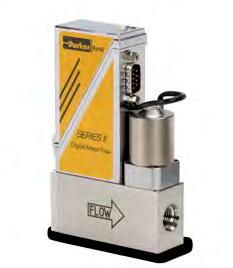
Mass Flow Meters and Controllers
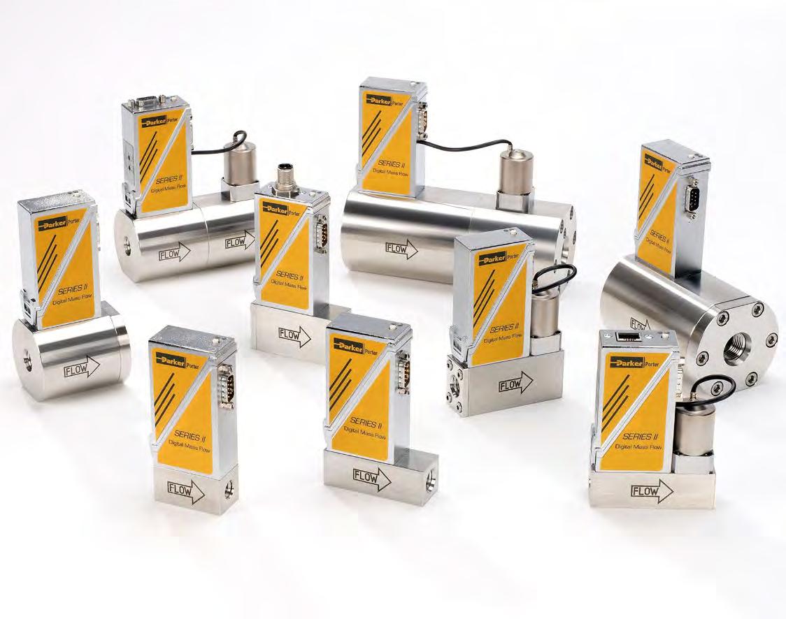
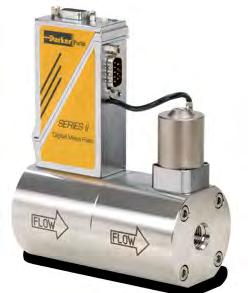
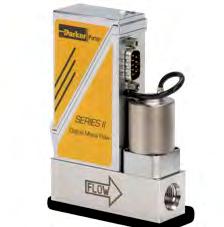
The original 500/600 Series Digital Mass Flow Products introduced the Porter standard of versatility and cost effectiveness to digital MFC’s. The new 500/600 SERIES II instruments take those concepts to a higher level. The instruments in the new SERIES II product line feature expanded flow ranges; from 0.014 - 0.7 cc/min up to 33 - 1670 l/min and are available with maximum operating pressures up to 5800 PSIA. SERIES II Mass Flow Products can be factory configured to include up to 8 gas type and flow range combinations with an effective turn down ratio of 150:1. In addition they can be configured with Porter’s Flow Parameter Adjust (FPA) feature. FPA offers increased flexibilty by providing user selection of both flow ranges and gas types while maintaining high accuracy and up to 150:1 effective turndown ranges for measurement and control.
A newly developed software tool and available connection hardware allows communication with the MFC through a Laptop USB port. With this package, the selection of different gas types and flow ranges is simple and intuitive. As a result, Original Equipment Manufacturers are able to significantly reduce the variety of spare instruments they keep in stock, thereby reducing the cost of ownership. Users of MFC’s in pilot plants or laboratories can rescale their instruments on site, saving time and cost.
Note: The flow ranges listed are the minimum and maximum nitrogen (N2) flow ranges available for each given model. Intermediate flow ranges are available. For correct sizing when operating parameters are questionable, please consult the factory. All flow ranges are at standard conditions of 14.7 PSIA and 70°F (21.1°C)
• Gas flow ranges from 0 - 0.7 ml/min up to 0 - 1670 l/min
• Operating pressures up to 5800 PSIA
• High accuracy and repeatability
• Storage of max. 8 calibration curves
• User configurable control characteristics
• Flow Parameter Adjust functionality up to 150 PSIA
• Effective rangeability <150:1
• Analog or digital: RS-232, DeviceNet™, Profibus-DP®, Modbus-RTU™
Measurement / Control System
Accuracy (incl. linearity) (based on actual calibration)
Turndown
Repeatability
Settling Time (Controller)
Control Stability
Standard: ±0.5% Reading plus ±0.1% Full Scale (±1% Full Scale for ranges 3-5 ml/min; ±2% Full Scale for ranges < 3 ml/min)
1 : 50 (in digital mode up to 1 : 187.5)
<0.2% Reading
Standard: 1-2 seconds
<±0.1% Full Scale (typical for 1 l/min N2)
Operating Temperature -10°C to +70°C
Temperature Sensitivity
Pressure Sensitivity
Zero: <0.05% Full Scale/°C; span: <0.05% Reading/°C
0.1%/ATM typical N2; 0.01%/ATM typical H2
Leak Integrity, outboard Tested < 2 x 10⁻⁹ mbar l/s He
Attitude Sensitivity
Warm-Up Time
Mechanical Parts
Max. error at 90° off horizontal 0.2% at 1 ATM, typical N2
30 min. for optimum accuracy
2 min. for accuracy ±2% Full Scale
Material (wetted parts) Stainless steel 316L or comparable
Surface Quality (wetted parts) Ra= 0.8µm typical
Process Connections Compression or face seal fittings
Seals
Standard: Viton® (FKM)
Options: EPDM, Kalrez® (FFKM)
Ingress Protection (housing) IP40
Electrical Properties
Power Supply
Power Consumption
Analog Output/Command
Digital Communication
Electrical Connection
Analog/RS-232
Profibus-DP®
DeviceNet™
+15-24 Vdc
Meter: 70 mA; Controller: max. 320 mA; Add 50 mA for Profibus®, if applicable
0-5 (10) Vdc or 0 (4)-20 mA – specify – (Sourcing output)
Standard: RS-232
Options: Profibus-DP®, DeviceNet™, Modbus™
9-pin D-connector (male)
Bus: 9-pin D-connector (female)
Power: 9-pin D-connector (male)
5-pin M12-connector (male)
Modbus-RTU™/FLOW-BUS RJ45 modular jack
Technical specifications and dimensions subject to change without notice.
Kalrez® is a registered trademark of DuPont Dow Elastomers L.L.C.; Viton® is a registered trademark of DuPont Performance Elastomers L.L.C.; DeviceNet™ is a trademark of ODVA; Modbus™ is a trademark of Schneider Automation Inc.; Profibus DP® is a trademark of PROFIBUS Nutzerorganisation e.V.
Product Type 4 Valve Only
5 Meter
6 Controller Pressure Rating
0 928 PSIA
1 1450 (1.45K)PSIA
2 2900 (2.9K) PSIA
3 5800 (5.8K) PSIA
Flow Ranges (Flow Controllers)
0CV 0.7/0-9 ml/min (928, 1.5K PSIA)
1CV 0-8 ml/min /0-25 l/min (928, 1.5K PSIA)
1AV 0-20/0-100 l/min (928, 1.5K PSIA)
2AV 0-40/0-250 l/min (928, 1.5K PSIA)
3AV 0-200/0-1670 l/min (928, 1.5K PSIA)
0M 0-10/0-500 ml/min (3K, 6K PSIA)
1M 0-.5/0-10 l/min (3K, 6K PSIA)
2M 0-10/0-100 l/min (3K, 6K PSIA)
Flow Ranges (Flow Meters)
0C 0-.7/0-9 ml/min (928, 1.5K PSIA)
1B 0-8 ml/min/0-25 l/min (928, 1.5K PSIA)
1AC 0-20/0-100 l/min (928, 1.5K PSIA)
2AC 0-40/0-250 l/min (928, 1.5K PSIA)
3AC 0-200/0-1670 l/min (928, 1.5K PSIA)
0M 0-10/0-500 ml/min (3K, 6K PSIA)
1M 0-15/0-20,000 ml/min (3K, 6K PSIA)
2M 0-10/0-250 l/min (3K, 6K PSIA)
3M 0-200/0-1250 l/min (3K, 6K PSIA)
Nominal Range Factory Selected
Elastomers
V Viton®
E EPDM
K Kalrez®
Connection (in/out)
1 1/8" OD Compression
2 1/4" OD Compression
3 6 mm OD Compression
4 12 mm OD Compression
5 1/2" OD Compression
6 20 mm Compression
8 1/4" Male Face Seal
9 Other 0 None
Supply Voltage
D +15 to 24 Vdc
Analog I/O
A 0 to 5 Vdc
B 0 to 10 Vdc
F 0 to 20 mA Sourcing
G 4 to 20 mA Sourcing
Communication (I/O)
A RS-232 + Analog, N.C. Valve
B RS-232 + Analog, N.O. Valve
D RS-232 + DeviceNet™, N.C. Valve
E RS-232 + DeviceNet™, N.O. Valve
M RS-232 + Modbus™, N.C. Valve
N RS-232 + Modbus™, N.O. Valve
P RS-232 + Profibus®, N.C. Valve
Q RS-232 + Profibus®, N.O. Valve
R RS-232 + FlowBus, N.C. Valve
S RS-232 + FlowBus, N.O. Valve
N.C. = Normally Closed
N.O. = Normally Opened
(Valid for operating conditions from 12 to 150 PSIA and 0°C to 70°C)
Notes:
• Flow parameter adjust is optional on the Series II and must be requested at the point of ordering
• Extended rangeability for digital communication only; turndown 50:1 when using analog I/O options
• The selected orifice of the control valve may limit the rangeability
• Standard accuracy ( based on actual calibration): +(0.5% RD + 0.1% FS); ranges from 0 - 5 to 0 - 10 ml/min: ±1% FS; ranges ≤ 0-5 ml/min: ±2% FS
• Series II factors for gas not in the above table are available from the factory
FAILURE OR IMPROPER SELECTION OR IMPROPER USE OF THE PRODUCTS DESCRIBED HEREIN OR RELATED ITEMS CAN CAUSE DEATH, PERSONAL INJURY AND PROPERTY DAMAGE.
This document and other information from Parker-Hannifin Corporation, its subsidiaries and authorized distributors provide product or system options for further investigation by users having technical expertise.
The user, through its own analysis and testing, is solely responsible for making the final selection of the system and components and assuring that all performance, endurance, maintenance, safety and warning requirements of the application are met. The user must analyze all aspects of the application, follow applicable industry standards, and follow the information concerning the product in the current product catalog and in any other materials provided from Parker or its subsidiaries or authorized distributors.
To the extent that Parker or its subsidiaries or authorized distributors provide component or system options based upon data or specifications provided by the user, the user is responsible for determining that such data and specifications are suitable and sufficient for all applications and reasonably foreseeable uses of the components or systems.
The items described in this document are hereby offered for sale by Parker-Hannifin Corporation, its subsidiaries or its authorized distributors. This offer and its acceptance are governed by the provisions stated in the detailed “Offer of Sale” elsewhere in this document or available at www.parker.com/offerofsale
FM-1280
RevA 01/2014
Parker Hannifin Corporation
Porter Instrument Division
245 Township Line Road Hatfield, Pennsylvania
phone 215 723 4000
fax 215 723 2199
industrial@parker.com
www.parker.com/porter
© 2014 Parker Hannifin Corporation