Value

The IR6200 Series regulator offers high pressure capability with an inlet pressure up to 4,000 psig. The large convoluted Hastelloy C-22® diaphragm provides stable pressure control over the operational range of the regulator.
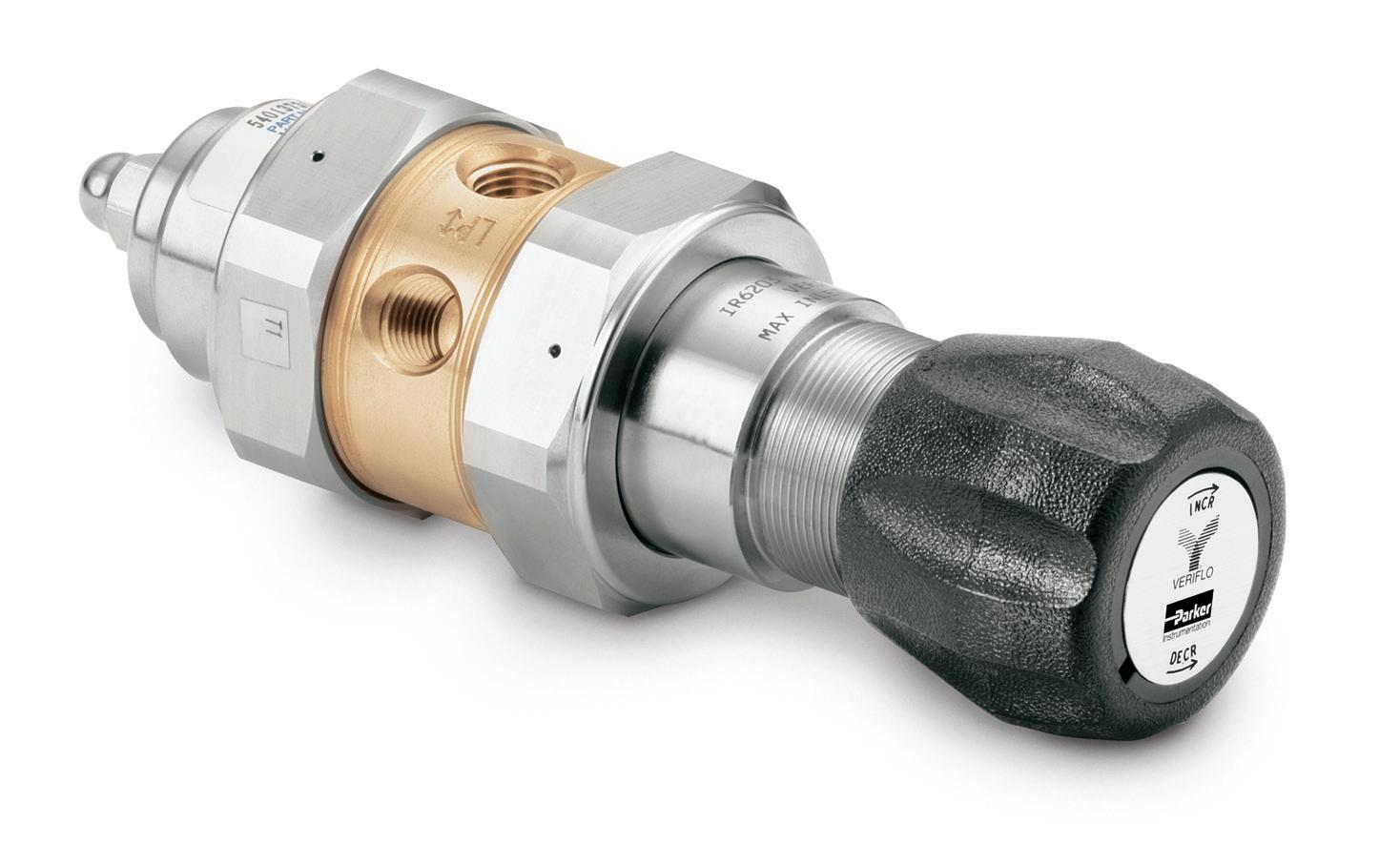
Close tolerances andtight alignment of moving components minimize hysteresis and improve cycle life. Convoluted, Hastelloy C-22® diaphragm provides high corrosion resistance and increases cycle life.
Veri flo green italic print 2 Contact Information: Veriflo Division phone 510 235 9590 fax 510 232 7396 veriflo.sales@parker.com
Proposition:
Two Stage, General Purpose Pressure Regulator Internally Threadless, Brass IR6200 Series Product Features:
Safety Guide and Installation and Operating Instructions available at www.parker.com/veriflo 50 55 60 65 70 75 80 85 90 95 100 105 0 20 40 60 80 100 120 140 160 180 200 220 240 260 280 300 IR6203 .06 Cv Inlet Pressure - 1500 PSIG N2 Flow (slpm) Outlet Pressure (psig) IR6202 .06 Cv Inlet Pressure - 1500 PSIG 15 20 25 30 35 40 45 50 55 60 65 0 20 40 60 80 100 120 140 160 180 200 220 240 N2 Flow (slpm) Outlet Pressure (psig) IR6201 .06 Cv Inlet Pressure - 1500 PSIG 0 2 4 6 8 10 12 14 16 18 20 22 24 26 28 30 32 0 20 40 60 80 100 120 140 160 180 200 220 N2 Flow (slpm) Outlet Pressure (psig) ø 1.44 [37mm] Hole Required In Panel For Mounting. Max Panel Thickness 1/4” [6.4mm] ø 2.32 [59mm] 4.33 [110mm] 1.98 [50mm] 1/8” NPT Captured Vent port 1/8” NPT Captured Vent port H IR6200 SERIES Flow Curves Dimensional Drawing RANGE TABLE Basic Model Max Inlet PSIG 0.06 Cv 0.02 Cv 0.15 Cv IR6200 4000 4000 1250 IR6201 4000 4000 1250 IR6202 4000 4000 1250 IR6203 4000 4000 1250 IR6204 4000 4000 1250 IR6215 4000 4000 1250 Additional flow curves available upon request
TABLE Basic Model H IR6200 7.22
IR6201 7.22
IR6202 7.22
IR6203 7.22
IR6204 7.81
IR6215 7.22 [183.4MM]
OVERALL HEIGHT
[183.4MM]
[183.4MM]
[183.4MM]
[183.4MM]
[198.4MM]
IR6200 SERIES
Ordering Information
Basic Series
Range Outlet Gauge
00 = 0 - 10 psig 0 - 30 psig
01 = 1 - 30 psig 0 - 60 psig
02 = 2 - 60 psig 0 - 100 psig
03 = 3 - 100 psig 0 - 200 psig
15 = 5 - 150 psig 0 - 200 psig 04 = 10 - 250 psig 0 - 400 psig
Body Material
B = Brass
Flow Capacity
= 0.06 Cv Standard
1 = 0.02 Cv
2 = 0.15 Cv
Seat Material
K = PCTFE
Porting
2P = 2 Ports No X required for gauges, inlet & outlet ports only
3P = 3 Ports One X for gauge port
4P = 4 Ports Two X’s for gauge ports
4PB = 4 Ports One X for gauge port
5P = 5 Ports Two X’s for gauge ports
6P = 6 Ports Two X’s for gauge ports
See Regulator Porting Guide for additional options and port layouts
Note: Ports may be plugged for NPT threaded product.
Outlet Gauge
Outlet Gauge
Basic Series
03 = 0 - 30 psig IR6200
OL = 0 - 60 psig IR6201
01 = 0 - 100 psig IR6202
2 = 0 - 200 psig IR6203
4 = 0 - 400 psig IR6204
X = No Gauge
Additional ranges available upon request
Inlet Gauge
X = No Gauge 30 = 3000 psig Standard 20 = 2000 psig with the 0.15 Cv option 40 = 4000 psig
Additional ranges available upon request
Port Style
2 = 1/8” NPT Female
4 = 1/4” NPT Female
6 = 3/8” NPT Female
4T = 1/4” A-LOK®
6T = 3/8” A-LOK®
All Gauge ports are 1/4” NPT Female
Port Mounting
B = Standard - No other options
Optional Features
This section can have multiple options
B = True Ported Body No plugs
G = Tamper Proof Not available with M option
M = Metal Knob Not available with G option
N = Nickel Plate
R2 = Relief Valve 4PB, 5P and 6P Only
S = Self Relieving
V = Outlet Valve NV17SB44MF
Note: Panel Mount Option: Order Panel Nut Ring p/n: 41900363 as a separate line item.
Vent Muffler Option: Order Vent Muffler p/n: 46600581 as a separate line item.
CGA#
330, 350, 510, 580
590
rated
1 2 3 4 5 6 7 8 9 10 11 1 2 3 4 5 6 7 8 9 10 11 IR62 02 B K 4P 01 30 4 B N 580 IR6202BK4P01304BN580 Sample: Finished Order: Build an IR6200 Series regulator by replacing the numbered symbols with an option from the corresponding tables below. Color Explanations:
an explanation of Ordering options
Black = Standard Lead Time Configurations Blue = Extended Lead Time Configurations Green Italic = Express Service Program (ESP)
320,
or
Do not exceed the
pressure of the CGA connection.
For
please reference literature 25000275 at www.parker.com/veriflo
IR6200 Series
Specifications
Functional Performance Design
Burst Pressure 12,000 psig (828 barg)
Proof Pressure 6,000 psig (414 barg)
Flow Capacity
Cv Options Cv 0.06 (std), Cv 0.02, Cv 0.15
Leak Rate
Internal Bubble Tight External Bubble Tight
Supply Pressure Effect
Based upon Cv Option
0.02 Cv 0.01 psig/100 psig (0.0007 barg/7 barg)
0.06 Cv 0.01 psig/100 psig (0.0007 barg/7 barg) 0.15 Cv 0.02 psig/100 psig (0.0014 barg/7 barg)
Internal Volume 8.1 cc without fittings
Approx. Weight 3.5 lbs. (1.6 kg)
Operating Conditions
Maximum Inlet Refer to Range Table for specific information
Outlet Options
0-10 psig (.7 barg), 1-30 psig (2 barg), 2-60 psig (4 barg), 3-100 psig (7 barg), 5-150 psig (10 barg),10-250 psig (17 barg)
Temperature -40°F to 150°F (-40°C to 66°C)
A-LOK®
The items described in this document are hereby offered for sale by Parker-Hannifin Corporation, its subsidiaries or its authorized distributors. This offer and its acceptance are governed by the provisions stated in the detailed “Offer of Sale” elsewhere in this document or available at www.parker.com/veriflo
!
FAILURE OR IMPROPER SELECTION OR IMPROPER USE OF THE PRODUCTS DESCRIBED HEREIN OR RELATED ITEMS CAN CAUSE DEATH, PERSONAL INJURY AND PROPERTY DAMAGE. THIS DOCUMENT IS FOR REFERENCE ONLY. PLEASE CONSULT FACTORY FOR LATEST PRODUCT DRAWINGS AND SPECIFICATIONS
This document and other information from Parker-Hannifin Corporation, its subsidiaries and authorized distributors provide product or system options for further investigation by users having technical expertise.
The user, through its own analysis and testing, is solely responsible for making the final selection of the system and components and assuring that all performance, endurance, maintenance, safety and warning requirements of the application are met. The user must analyze all aspects of the application, follow applicable industry standards, and follow the information concerning the product in the current product catalog and in any other materials provided from Parker or its subsidiaries or authorized distributors.
To the extent that Parker or its subsidiaries or authorized distributors provide component or system options based upon data or specifications provided by the user, the user is responsible for determining that such data and specifications are suitable and sufficient for all applications and reasonably foreseeable uses of the components or systems.
The products described herein, including without limitation, product features, specifications, designs, availability and pricing are subject to change by Parker Hannifin Corp and it’s subsidiaries at any time without notice.
Proposition 65 Warning: This product contains chemicals known to the state of California to cause cancer or birth defects or other reproductive harm.
Use mobile device to scan this QR Code.

Veriflo
LitPN:
Rev: H Date of Issue 03/2013 © 2007 Parker
Corporation
25000227
Hannifn
Wetted
Options Brass (std) or Nickel Plated Brass Compression Member Inconel 625®
Bronze
Seat
Screen
Filter
and
Self Relieving Seat
Non-wetted
Nickel Plated
Nut Nickel
Options ABS
or
additional information on materials of construction, functional performance and operating conditions, see
Materials of Construction
Body
Diaphragm Hastelloy C-22® Poppet Phosphor
Poppet Spring Inconel X750®
PCTFE Carrier 316L Stainless Steel Washer Back-up Phosphor Bronze O-ring Back-up FKM Inlet
/
Copper
Phosphor Bronze
PEEK™
Cap
Brass
Plated Brass Knob
(std) (ambient temp)
Aluminum For
Regulator Technical Bulletin.
is a registered trademark of Parker Hannifin Corporation Hastelloy C-22® and Hastelloy C-276® are registered trademarks of Haynes International, Inc. Inconel® is a registered trademark of Special Metals Corporation. PEEK™ is a trademark of Victrex plc.
