


Needle Valves Catalog 4110-NV December 2010

ii
Catalog 4110-NV Overview
Parker Hannifin Corporation Instrumentation Products Division Jacksonville, AL USA http://www.parker.com/ipdus
RESPONSIBILITY
1
Catalog 4110-NV Table of Contents © Copyright 2010 Parker Hannifin Corporation. All Rights Reserved. Description ........................................................................................... Page V Series Needle Valves – Integral Bonnet, 5,000 PSI Maximum* ............... 2 U Series Needle Valves – Union Bonnet, 6,000 PSI Maximum* ............... 12 VQ Series Toggle Valves – 600 PSI Maximum* 18 NP6 Series Needle Valves – Screwed Bonnet, 6,000 PSI Maximum* ....... 24 SN6 Series Needle Valves – Integral Bonnet, 6,000 PSI Maximum* 28 PV Series Needle Valves – Rising Stem Plug Valve, 6,000 PSI Maximum* 32 MPN Series Needle Valves – 20,000 PSI Maximum* ................................ 36 Sample Cylinders and Accessories ........................................................... 44 End Connections ....................................................................................... 50 Offer of Sale .............................................................................................. 51 * Actual pressure rating will be determined by the valve configuration, body material, seat material and other factors. V U VQ NP6 End Conn SN6 PV MPN Cyl & Acc Offer of Sale The items described in this document are hereby offered for sale by Parker-Hannifin Corporation, its subsidiaries or its authorized distributors. This offer and its acceptance are governed by the provisions stated in the detailed “Offer of Sale” elsewhere in this document or available at www.parker.com/ipdus.
Parker Hannifin Corporation Instrumentation Products Division Jacksonville, AL USA http://www.parker.com/ipdus
FAILURE OR IMPROPER SELECTION OR IMPROPER USE OF THE PRODUCTS DESCRIBED HEREIN OR RELATED ITEMS CAN CAUSE DEATH, PERSONAL INJURY AND PROPERTY DAMAGE. This document and other information from Parker-Hannifin Corporation, its subsidiaries and authorized distributors provide product or system options for further investigation by users having technical expertise.
user, through its own analysis and testing, is solely responsible for making the final selection of the system and components and assuring that all performance, endurance, maintenance, safety and warning requirements of the application are met. The user must analyze all aspects of the application, follow applicable industry standards, and follow the information concerning the product in the current product catalog and in any other materials provided from Parker or its subsidiaries or authorized distributors.
the extent that Parker or its subsidiaries or authorized distributors provide component or system options based upon data or specifications provided by the user, the user is responsible for determining that such data and specifications are suitable and sufficient for all applications and reasonably foreseeable uses of the components or systems.
WARNING – USER
The
To
V Series Needle Valves
Introduction
Parker V Series Needle Valves are designed for positive leak tight shut-off and regulation of fluids in process, power, and instrumentation applications. With a wide variety of port sizes and styles, temperature capabilities ranging from -65°F to 450°F (-54°C to 232°C) and pressures to 5000 psig (345 bar), V Series Needle Valves provide the user with the utmost in flexibility when designing miniaturized tubing or piping systems.
Features
Choice of three stem types: R-Stem – All metal, blunt stem tip N-Stem – All metal, tapered needle stem tip K-Stem – PCTFE stem tip
Differential hardness between the strain hardened stem and cold formed body threads provides improved cycle life
Choice of PTFE packing or elastomeric O-ring stem seals
316 Stainless Steel, Steel, Brass and Monel® Alloy 400 construction
Inline and angle patterns
Wide variety of US Customary and SI ports
Panel mountable
100% factory tested
Optional color coded handles
Specifications
Pressure Ratings:
316 Stainless Steel: 5000 psig (345 bar) CWP Brass, Steel and Monel® Alloy 400: 3000 psig (207 bar) CWP
Orifice: 0.078" to 0.312" (2.0mm to 7.9mm)
CV: 0.12 to 1.90
Port size: 1/8" to 3/4" (3mm to 12mm)
Temperature Ratings:
Stainless Steel and Monel® Alloy 400: -65°F to 450°F (-54°C to 232°C)
Brass: -65°F to 400°F (-54°C to 204°C)
Steel: -20°F to 350°F (-29°C to 177°C)
PTFE Packing: -65°F to 450°F (-54°C to 232°C)
PCTFE Stem Tip: -65°F to 350°F (-54°C to 177°C)
Nitrile Rubber Stem Seal: -30°F to 250°F (-34°C to 121°C)
Fluorocarbon Rubber Stem Seal: -15°F to 400°F (-26°C to 204°C)
Ethylene Propylene Rubber Stem Seal: -70°F to 275°F (-57°C to 135°C)
Note: When combining body, seat and seal materials, the most restrictive temperature rating becomes the limiting factor on temperature range.
Monel® Alloy 400 is the registered trademark of Special Metals Corporation.
http://www.parker.com/ipdus
2
Catalog 4110-NV
Parker Hannifin Corporation Instrumentation Products Division Jacksonville, AL USA
V
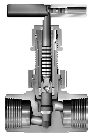
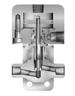
Model Shown: 4Z-V4LK-SS
Materials of Construction (with PTFE Packing) Model Shown: 4Z-V4LK-SS O-Ring Stem Seal 3 2 4 1 6 7 8 5
3 Parker Hannifin Corporation Instrumentation Products Division Jacksonville, AL USA http://www.parker.com/ipdus Catalog 4110-NV V Series Needle Valves V Item # Part Description Stainless Steel Brass Steel Monel® Alloy 400 1 Body ASTM A 182 Type F316 ASTM B 283 Alloy C37700 ASTM A 576 Grade 1214 ASTM B 564 Alloy N04400 2 Packing Nut ASTM A 479 Type 316 ASTM A 479 Type 316 ASTM A 479 Type 316 ASTM A 479 Type 316 3 Handle* Nylon 6/6 with SS insert Nylon 6/6 with SS insert Nylon 6/6 with SS insert Nylon 6/6 with SS insert 4 Lower Packing Washer ASTM A 479 Type 316 ASTM A 479 Type 316 ASTM A 479 Type 316 ASTM B 164 Alloy N04400 5 Handle Screw Stainless Steel Stainless Steel Stainless Steel Stainless Steel 6 Packing** PTFE PTFE PTFE PTFE 7 Stem ( R and N Stem) ASTM A 276 Type 316 ASTM A 276 Type 316 ASTM A 276 Type 316 ASTM B 164 Alloy N04400 7A Stem (K Stem) ASTM A 276 Type 316, with PCTFE ASTM A 276 Type 316, with PCTFE ASTM A 276 Type 316, with PCTFE ASTM B 164 with PCTFE 8 Upper Packing Washer Brass Brass Brass Brass 9 Panel Nut*** 316 Stainless Steel 316 Stainless Steel 316 Stainless Steel 316 Stainless Steel * Handles for V8 and V12 Series Valves with R and N Stems are aluminum T-bars. ** Optional O-ring elastomeric stem seals are available – See How to Order. *** Panel Nut is nickel plated brass on V2 Series Valves. Panel Nuts must be ordered separately – see page 10. Lubrication: Perfluorinated Polyether Note: To determine MPa, multiply bar by 0.1 Pressure vs. Temperature Materials of Construction (with PTFE Packing) K PCTFE tipped N Needle (2-1/2°) R Blunt (30°) Stem Types
2A-V2LN 2A-V2AN Needle 0.12 0.80 0.14 0.63
2A-V2LK 2A-V2AK PCTFE 0.13 0.83 0.14 0.63
25.7 1.01 25.7
2F-V2LR 2F-V2AR 1/8" Female NPT Blunt 0.093 2.4 0.13 0.61 0.16 0.49 0.94 23.9 0.94 23.9
2F-V2LN 2F-V2AN Needle 0.12 0.66 0.18 0.39
2F-V2LK 2F-V2AK PCTFE 0.12 0.73 0.17 0.54
2M-V2LR 2M-V2AR 1/8" Male NPT Blunt 0.093 2.4 0.13 0.61 0.16 0.49 0.75 19.1 0.75 19.1
2M-V2LN 2M-V2AN Needle 0.12 0.66 0.18 0.39
2M-V2LK 2M-V2AK PCTFE 0.12 0.73 0.17 0.54
2Z-V2LR 2Z-V2AR 1/8" Compression CPI™ Blunt 0.078 2.0 0.12 0.78 0.14 0.67 1.01 25.7 1.01 25.7
2Z-V2LN 2Z-V2AN Needle 0.12 0.80 0.14 0.63
2Z-V2LK 2Z-V2AK PCTFE 0.13 0.83 0.14 0.63
4A-V2LR 4A-V2AR 1/4" Compression A-LOK® Blunt 0.078 2.0 0.12 0.78 0.14 0.67 1.09 27.7 1.09 27.7
4A-V2LN 4A-V2AN Needle 0.12 0.80 0.14 0.63
4A-V2LK 4A-V2AK PCTFE 0.13 0.83 0.14 0.63
4Z-V2LR 4Z-V2AR 1/4" Compression CPI™ Blunt 0.078 2.0 0.12 0.78 0.14 0.67 1.09 27.7 1.09 27.7
4Z-V2LN 4Z-V2AN Needle 0.12 0.80 0.14 0.63 4Z-V2LK 4Z-V2AK PCTFE 0.13 0.83 0.14 0.63
* Tested in accordance with ISA S75.02. Gas flow will be choked when P1 - P2 / P1 = XT † For CPI™ and A-LOK®, dimensions are measured with nuts in the finger tight position.
Dimensions in inches/millimeters are for reference only, subject to change.
4
Catalog 4110-NV V Series Needle Valves V B
Max Open
Min
A .43
.41
B A 1.38 (35.1) Max Open
Min Close
.41
.43
B A .94
B .31
.94
Max Open
A
V2 Series Dimensions / Flow Data Model Shown: 4A-V4AN-BN-B Model Shown: 4M4Z-V4LK-SS ( ) Denotes dimensions in millimeters Panel Hole Diameter: 0.52 (13.2) Max Panel Thickness: 0.25 (6.4) V4 Series Model Shown: 2M-V2LN-SS Model Shown: 2F-V2AR-V-SS Panel Hole Diameter:
Max Panel Thickness:
Basic Part Number End Connections Stem Type Flow Data Dimensions Inlet (Port 1) Outlet (Port 2) Orifice Inline Angle A† B† Inline Angle Inch mm C V X T * C V X T * Inch mm Inch mm
Parker Hannifin Corporation Instrumentation Products Division Jacksonville, AL USA http://www.parker.com/ipdus
1.38 (35.1)
2.22 (56.4)
Close 2.02 (51.3)
(10.9)
(10.4)
2.22 (56.4)
2.02 (51.3)
(10.4)
(10.9)
(23.9) Max Open 2.25 (57.2) Min Close 1.93 (49.0) .31 (7.9) .43 (10.9)
(7.9)
(23.9)
2.25 (57.2) Min Close 1.93 (49.0)
.43 (10.9)
0.45 (11.4)
0.25 (6.4)
1/8" Compression A-LOK® Blunt
0.12
2A-V2LR 2A-V2AR
0.078 2.0
0.78 0.14 0.67 1.01
1.81 (46.0) *
1.81 (46.0) *
Max Open 2.58 (65.5) Min Close 2.25 (57.2) .44 (11.2) .53 (13.5)
B A
B .53 (13.5)
Max Open 2.58 (65.5) Min Close 2.25 (57.2)
.44 (11.2)
A
4F-V6LR 4F-V6AR 1/4" Female NPT Blunt 0.228 5.8 0.73 0.90 1.23 0.50 0.94 23.9 0.94 23.9
4F-V6LN 4F-V6AN Needle 0.55 0.61 0.92 0.62
4F-V6LK 4F-V6AK PCTFE 0.80 0.87 1.23 0.56
6A-V6LR 6A-V6AR 3/8" Compression A-LOK® Blunt 0.228 5.8 0.73 0.90 1.23 0.50 1.29 32.8 1.29 32.8
6A-V6LN 6A-V6AN Needle 0.55 0.61 0.92 0.62
6A-V6LK 6A-V6AK PCTFE 0.80 0.87 1.23 0.56
6M-V6LR 6M-V6AR 3/8" Male NPT Blunt 0.228 5.8 0.73 0.90 1.23 0.50 1.03 26.2 1.03 26.2
6M-V6LN 6M-V6AN Needle 0.55 0.61 0.92 0.62
6M-V6LK 6M-V6AK PCTFE 0.80 0.87 1.23 0.56
6Z-V6LR 6Z-V6AR
6Z-V6LN 6Z-V6AN Needle 0.55 0.61 0.92 0.62
3/8" Compression CPI™ Blunt 0.228 5.8 0.73 0.90 1.23 0.50 1.29 32.8 1.29 32.8
6Z-V6LK 6Z-V6AK PCTFE 0.80 0.87 1.23 0.56
8A-V6LR 8A-V6AR 1/2" Compression A-LOK® Blunt 0.228 5.8 0.73 0.90 1.23 0.50 1.40 35.6 1.40 35.6
8A-V6LN 8A-V6AN Needle 0.55 0.61 0.92 0.62
8A-V6LK 8A-V6AK PCTFE 0.80 0.87 1.23 0.56
8Z-V6LR 8Z-V6AR 1/2" Compression CPI™ Blunt 0.228 5.8 0.73 0.90 1.23 0.50 1.40 35.6 1.40 35.6
8Z-V6LN 8Z-V6AN Needle 0.55 0.61 0.92 0.62
8Z-V6LK 8Z-V6AK PCTFE 0.80 0.87 1.23 0.56
M10A-V6LR M10A-V6AR
M10A-V6LN M10A-V6AN Needle 0.55 0.61 0.92 0.62 M10A-V6LK M10A-V6AK PCTFE 0.80 0.87 1.23 0.56 M10Z-V6LR M10Z-V6AR
10mm Compression A-LOK® Blunt 0.228 5.8 0.73 0.90 1.23 0.50 1.30 33.0 1.30 33.0
10mm Compression CPI™ Blunt 0.228 5.8 0.73 0.90 1.23 0.50 1.30 33.0 1.30 33.0
M10Z-V6LN M10Z-V6AN
PCTFE 0.80 0.87 1.23 0.56
Needle 0.55 0.61 0.92 0.62 M10Z-V6LK M10Z-V6AK
* Tested in accordance with ISA S75.02. Gas flow will be choked when P1 - P2 / P1 = XT † For CPI™ and A-LOK®, dimensions are measured with nuts in the finger tight position.
Dimensions in inches/millimeters are for reference only, subject to change.
6
Products
Catalog 4110-NV V Series Needle Valves V V6 Series Dimensions / Flow Data
* Note: Handle diameter for K Stem V6 Series Valves is 1.38 (35.4) ( ) Denotes dimensions in millimeters Basic Part Number End Connections Stem Type Flow Data Dimensions Inlet (Port 1) Outlet (Port 2) Orifice Inline Angle A† B† Inline Angle Inch mm C V X T * C V X T * Inch mm Inch mm
Parker Hannifin Corporation Instrumentation
Division Jacksonville, AL USA http://www.parker.com/ipdus
Model Shown: 6M4F-V6LR-V-SS Model Shown: 4F6Z-V6AK-SS Panel Hole Diameter: 0.45 (11.4) Max Panel Thickness: 0.25 (6.4)
6F-V8LR 6F-V8AR
*
2.75 (69.9) .59 (15.0)
* B
6F-V8LN 6F-V8AN Needle 1.05 0.83 1.28 0.80
6F-V8LK 6F-V8AK PCTFE 1.29 0.91 1.90 0.76
Max Open 3.01 (76.5) Min Close 2.23 (56.6) A
.58 (14.7)
3/8" Female NPT Blunt 0.312 7.9 1.23 0.87 1.66 0.72 1.34 34.0 1.34 34.0
8A-V8LR 8A-V8AR 1/2" Compression A-LOK® Blunt 0.312 7.9 1.23 0.87 1.66 0.72 1.53 38.9 1.53 38.9
8A-V8LN 8A-V8AN Needle 1.05 0.83 1.28 0.80
8A-V8LK 8A-V8AK PCTFE 1.29 0.91 1.90 0.76
8M-V8LR 8M-V8AR 1/2" Male NPT Blunt 0.312 7.9 1.23 0.87 1.66 0.72 1.34 34.0 1.34 34.0 8M-V8LN 8M-V8AN Needle 1.05 0.83 1.28 0.80 8M-V8LK 8M-V8AK PCTFE 1.29 0.91 1.90 0.76 8Z-V8LR 8Z-V8AR 1/2" Compression CPI™ Blunt 0.312 7.9 1.23 0.87 1.66 0.72 1.53 38.9 1.53 38.9 8Z-V8LN 8Z-V8AN Needle 1.05 0.83 1.28 0.80 8Z-V8LK 8Z-V8AK PCTFE 1.29 0.91 1.90 0.76
M10A-V8LR M10A-V8AR
10mm Compression A-LOK® Blunt 0.281 7.1 1.13 0.79 1.52 0.66 1.42 36.1 1.42 36.1 M10A-V8LN M10A-V8AN Needle 0.97 0.78 1.18 0.75 M10A-V8LK M10A-V8AK PCTFE 1.18 0.80 1.69 0.66 M10Z-V8LR M10Z-V8AR
10mm Compression CPI™ Blunt 0.281 7.1 1.13 0.79 1.52 0.66 1.42 36.1 1.42 36.1
M10Z-V8LN M10Z-V8AN Needle 0.97 0.78 1.18 0.75 M10Z-V8LK M10Z-V8AK PCTFE 1.18 0.80 1.69 0.66 M12A-V8LR M12A-V8AR
M12A-V8LN M12A-V8AN Needle 0.97 0.78 1.18 0.75 M12A-V8LK M12A-V8AK PCTFE 1.18 0.80 1.69 0.66
M12Z-V8LR M12Z-V8AR
M12Z-V8LN M12Z-V8AN
12mm Compression A-LOK® Blunt 0.281 7.1 1.13 0.79 1.52 0.66 1.51 38.4 1.51 38.4
12mm Compression CPI™ Blunt 0.281 7.1 1.13 0.79 1.52 0.66 1.51 38.4 1.51 38.4
Needle 0.97 0.78 1.18 0.75
PCTFE 1.18 0.80 1.69 0.66 * Tested in accordance with ISA S75.02. Gas flow will be choked when P1 - P2 / P1 = XT † For CPI™ and A-LOK®, dimensions are measured with nuts in the finger tight position.
M12Z-V8LK M12Z-V8AK
Dimensions in inches/millimeters are for reference only, subject to change.
7
Products Division
Catalog 4110-NV V Series Needle Valves V
V8 Series Dimensions / Flow Data * Note: Handles for N or R Stem V8 Series Valves are a T-bar ( ) Denotes dimensions in millimeters Basic Part Number End Connections Stem Type Flow Data Dimensions Inlet (Port 1) Outlet (Port 2) Orifice Inline Angle A† B† Inline Angle Inch mm C V X T * C V X T * Inch mm Inch mm
Parker Hannifin Corporation Instrumentation
Jacksonville, AL USA http://www.parker.com/ipdus
Model Shown: 8M-V8AN-EPR-SS Model Shown: 8Z6F-V8LK-SS Panel Hole Diameter: 0.77 (19.6) Max Panel Thickness: 0.40 (10.2)
2.75 (69.9) *
B A
.64 (16.3)
Max Open 3.01 (76.5) Min Close 2.23 (56.6) .61 (15.5)
Panel Hole Diameter: 0.77 (19.6) Max Panel Thickness: 0.40 (10.2)
*
1.81 (46.0) .61 (15.5)
B
.64 (16.3)
Max Open 3.01 (76.5) Min Close 2.23 (56.6) A
Model Shown: 8M8F-V12AK-BN-SS
8F-V12LR 8F-V12AR 1/2" Female NPT Blunt 0.312 7.9 1.23 0.87 1.66 0.72 1.38 35.1 1.38 35.1 8F-V12LN 8F-V12AN Needle 1.05 0.83 1.28 0.80
8F-V12LK 8F-V12AK PCTFE 1.29 0.91 1.90 0.76 8W-V12LR 8W-V12AR 1/2" Tube Socket Weld Blunt 0.312 7.9 1.23 0.87 1.66 0.72 1.12 28.4 1.12 28.4 8W-V12LN 8W-V12AN Needle 1.05 0.83 1.28 0.80 8W-V12LK 8W-V12AK PCTFE 1.29 0.91 1.90 0.76 10A-V12LR 10A-V12AR 5/8" Compression A-LOK® Blunt 0.312 7.9 1.23 0.87 1.66 0.72 1.52 38.6 1.52 38.6 10A-V12LN 10A-V12AN Needle 1.05 0.83 1.28 0.80 10A-V12LK 10A-V12AK PCTFE 1.29 0.91 1.90 0.76 10Z-V12LR 10Z-V12AR
5/8" Compression CPI™ Blunt 0.312 7.9 1.23 0.87 1.66 0.72 1.52 38.6 1.52 38.6 10Z-V12LN 10Z-V12AN Needle 1.05 0.83 1.28 0.80 10Z-V12LK 10Z-V12AK PCTFE 1.29 0.91 1.90 0.76 12A-V12LR 12A-V12AR
3/4" Compression A-LOK® Blunt 0.312 7.9 1.23 0.87 1.66 0.72 1.52 38.6 1.52 38.6 12A-V12LN 12A-V12AN Needle 1.05 0.83 1.28 0.80 12A-V12LK 12A-V12AK PCTFE 1.29 0.91 1.90 0.76 12Z-V12LR 12Z-V12AR 3/4" Compression CPI™ Blunt 0.312 7.9 1.23 0.87 1.66 0.72 1.52 38.6 1.52 38.6 12Z-V12LN 12Z-V12AN Needle 1.05 0.83 1.28 0.80 12Z-V12LK 12Z-V12AK PCTFE 1.29 0.91 1.90 0.76
* Tested in accordance with ISA S75.02. Gas flow will be choked when P1 - P2 / P1 = XT † For CPI™ and A-LOK®, dimensions are measured with nuts in the finger tight position.
Dimensions in inches/millimeters are for reference only, subject to change.
8
Catalog 4110-NV V Series Needle Valves V V12 Series Dimensions / Flow Data
Parker Hannifin Corporation Instrumentation Products Division Jacksonville, AL USA http://www.parker.com/ipdus
Model Shown: 10Z-V12LN-B
* Note: Handles for N or R Stem V12 Series Valves are a T-bar ( ) Denotes dimensions in millimeters
Basic Part Number End Connections Stem Type Flow Data Dimensions Inlet (Port 1) Outlet (Port 2) Orifice Inline Angle A† B† Inline Angle Inch mm C V X T * C V X T * Inch mm Inch mm
Catalog 4110-NV
How to Order
Dimensions in inches/millimeters are for reference only, subject to change.
V Series Needle Valves
The correct part number is easily derived from the following example and ordering chart. The six product characteristics required are coded as shown in the chart.
Example 1, below, describes an angle pattern V4 Series needle valve equipped with 1/4" CPI™ compression inlet and outlet ports, a PCTFE tipped stem, Nitrile seals, and stainless steel construction.
Example 2, below, describes an inline pattern V6 Series needle valve equipped with 1/4" male NPT inlet port, 1/4" female NPT outlet port, a needle stem type, PTFE stem seal, brass construction.
Example 1: 4Z-V4AK-BN-SS (shown in the part number blocks below)
Example 2: 4M4F-V6LN-B
4Z
Outlet Port* Inlet Port*
Inlet
– – –
V4
AK Valve Series
Stem Type
Stem Seal
BN SS Body Material
2A 2M 4A
2F 2Z 4Z V2 R Blunt (30°) N Needle (2-1/2°)
2A 4A 6A M6A
2F 4M 6Z M6Z
2M 4W M3A M8A
2Z 4Z M3Z M8Z
4A 6A 8A M10A
4F 6M 8Z M10Z
4M 6W M8A M12A
4Z 6Z M8Z M12Z
4F 6Z 8Z M12A
6A 8A M10A M12Z
6F 8M M10Z
V4
V6
K PCTFE
Blank PTFE BN Nitrile Rubber EPR Ethylene Propylene Rubber V Fluorocarbon Rubber
SS Stainless Steel S Steel M Monel® Alloy 400 B Brass
V8
8W 10Z 12Z V12
8F 10A 12A
*If the inlet and outlet ports are the same, eliminate the outlet port designator.
How to Order Options
Colored Round Handles – Add the designator corresponding to the correct handle color as a suffix to the part number. Black is standard, W - white, B - blue, G - green, R - red, Y - yellow. Example: M10A-V6LK-SS-G
Oxygen Cleaning – Add the suffix -C3 to the end of the part number to receive valves cleaned and assembled for oxygen service in accordance with Parker Specification ES8003. Example: 4A-V4AN-EPR-SS-C3
Parker Hannifin Corporation Instrumentation Products Division Jacksonville, AL USA http://www.parker.com/ipdus
9
V
Port* Outlet Port* Valve Series Stem Type
Stem Seal Body Material
V
V Series Needle Valves
How to Order Components
Colored Round Nylon Handles with Handle Screw – Valve Series-Handle-Color. Example: V4-HANDLE-BLUE Stainless Steel T-Bar Handles with Handle Screw – Examples: V2: V2-BAR-HANDLE-SS; V4: V4-BAR-HANDLE-SS; V6: V6-BAR-HANDLE-SS; V8: U12-BAR-HANDLE-SS; V12: U12-BAR-HANDLE-SS
Aluminum T-Bar Handles with Handle Screw – Examples: V2: Not available; V4: V4-BAR-HANDLE-AL; V6: V4-BAR-HANDLE-AL; V8: U12-BAR-HANDLE-AL; V12: U12-BAR-HANDLE-AL
Panel Mounting Nuts – Examples: V2: 2-Panel-Nut-SS; V4: 4-Panel-Nut-SS; V6: 6-Panel-Nut-SS; V8: 8-Panel-Nut-SS
How to Order Maintenance Kits
PTFE Packing Stem Kits – Consists of One Stem; One PTFE Packing; One Upper Packing Washer; One Lower Packing Washer; One Packing Nut; Maintenance Instructions. Kit-Valve Series and StemType-Body Material. Examples: KIT-V4K-SS; KIT-V6N-B
Fluorocarbon Rubber Packing Stem Kits – Consists of One Stem; One Fluorocarbon Rubber O-ring Seal; One O-ring Back-up Gland; One O-ring Gland; One Lower Packing Washer; One Packing Nut; Maintenance Instructions.
Kit-Valve Series and Stem Type-V-Body Material. Examples: KIT-V2R-V-B; KIT-V4K-V-SS
Nitrile Rubber Packing Stem Kits – Consists of One Stem; One Nitrile Rubber O-ring Seal; One O-ring Back-up Gland; One O-ring Gland; One Lower Packing Washer; One Packing Nut; Maintenance Instructions.
Kit-Valve Series and Stem Type-BN-Body Material. Examples: KIT-V2R-BN-B; KIT-V4K-BN-SS
Ethylene Propylene Rubber Packing Stem Kits – Consists of One Stem; One Ethylene Propylene Rubber O-ring Seal; One O-ring Back-up Gland; One O-ring Gland; One Lower Packing Washer; One Packing Nut; Maintenance Instructions.
Kit-Valve Series and Stem Type-EPR-Body Material. Examples: KIT-V2R-EPR-B; KIT-V4K-EPR-SS
Parker Hannifin Corporation Instrumentation Products Division Jacksonville, AL USA http://www.parker.com/ipdus
10
Catalog 4110-NV
11
Catalog 4110-NV V Notes
Parker Hannifin Corporation Instrumentation Products Division Jacksonville, AL USA http://www.parker.com/ipdus
U
U Series Needle Valves
Introduction
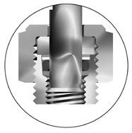
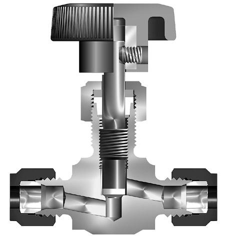
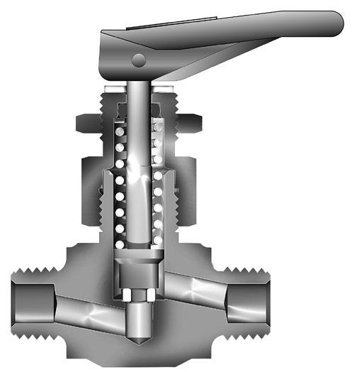
Parker U Series Union Bonnet Valves have been engineered for use at pressures up to 6,000 (414 bar) and temperatures as high as 1,200°F (649°C). A non-rotating lower stem helps to extend packing life by removing rotation from the packing area. Stem packing below the threads isolates the thread lubricant from the flow, ensuring adequate lubrication regardless of the media.
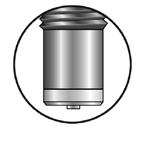
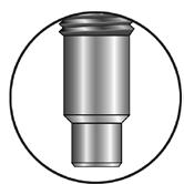
Features Union bonnet design ensures high integrity seal under severe service applications Packing below the power threads protects thread lubricants from media and isolates the lubricants from the media Dust seal in the packing nut protects stem threads from external contamination Stem swivel above the packing eliminates entrapment area and increases packing life Choice of Grafoil® or PTFE packing Choice of Regulating or Blunt stem types. Blunt stem type helps combat wire draw which may occur when two phase flow is present (i.e. steam service)
316 stainless steel construction
Wide variety of US Customary and SI ports Panel mountable 100% factory tested
Specifications
Pressure Rating: 6000 psig (414 bar) CWP
Temperature Rating: PTFE packing: -65°F to 450°F (-54°C to 232°C) Grafoil® packing: -65°F to 700°F (-54°C to 371°C) Grafoil® packing with HT option: -65°F to 1200°F (-54°C to 649°C)
Orifice: .177" to .437" (4.5mm to 11.1mm)
CV: .53 to 3.55
Pressure Rating and Tubing Selection:
For working pressures of A-LOK® and CPI™ tube connections, please see the Instrument Tubing Selection Guide (Bulletin 4200-TS), found in the Technical Section of the Parker Instrumentation Products Master Binder, or the Parker Instrument Tube Fitting Installation Manual (Bulletin 4200-B4). For working pressures of valves with external or internal pipe threads, please see Catalog 4260, Instrumentation Pipe Fittings.
Parker Hannifin Corporation Instrumentation Products Division Jacksonville, AL USA http://www.parker.com/ipdus
12
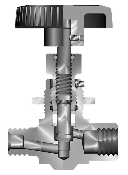
Catalog 4110-NV
Model Shown: 16F-U16LR-G-SS Materials of Construction Item # Description Material *1 Body ASTM A 182, Type F316 2 Bonnet Nut ASTM A 479, Type 316 *3 Bonnet ASTM A 479, Type 316 *4 Lower Stem* ASTM A 564, Type 630 5 Upper Stem ASTM A 564, Type 630 6 Stem Guide ASTM A 581, Type 416 7 Ball 440-C Stainless Steel *8 Bonnet Seal** Nickel-Chromium-Iron Alloy 9 Packing Nut ASTM A 479, Type 316 *10 Packing*** Grafoil® *11 Packing Washer 316 Stainless Steel 12 Handle**** Aluminum 13 Handle Screw 316 Stainless Steel 14 Dust Seal***** Nylon 6/6 15 Locking Nut Stainless Steel * Wetted parts * Lower Stem material is ASTM A 276 Type 316 with HT option ** Not required on U6 and U12 Series which have metal-to-metal seals *** Optional PTFE Packing is available **** Handle
is a registered trademark GrafTech
material is stainless steel with HT option ***** Dust Seal not available with HT option Lubrication: Molybdenum disulfide with soft metallic fillers Grafoil®
International Holdings, Inc.
Pressure vs. Temperature
Flow Characteristics
U6 Series Dimensions / Flow Data
2.00 (50.8) 2.00 (50.8)
Panel Hole Diameter: 0.65 (16.5)
Max Panel Thickness: 0.42 (10.7)
Model Shown: 4Z-U6LB-T-SS
Max Open 3.98 (101.1) Min Close 3.43 (87.1)
1.34 (34.0)
.59 (15.0)
Model Shown: 4F-U6AR-T-SS
A
B
( ) Denotes dimensions in millimeters
B .59 (15.0)
Max Open 3.98 (101.1) Min Close 3.43 (87.1) A
1.34 (34.0)
2F-U6LR 2F-U6AR 1/8" Female NPT Regulating 0.188 4.8 0.58 0.83 0.77 0.70 1.00 25.4 1.00 25.4
2F-U6LB 2F-U6AB Blunt 0.69 0.50 0.91 0.42
4A-U6LR 4A-U6AR 1/4" Compression A-LOK® Regulating 0.177 4.5 0.53 0.80 0.70 0.67 1.38 35.1 1.38 35.1
4A-U6LB 4A-U6AB Blunt 0.65 0.48 0.86 0.40
4F-U6LR 4F-U6AR 1/4" Female NPT Regulating 0.228 5.8 0.78 0.95 1.04 0.80 1.03 26.2 1.03 26.2
4F-U6LB 4F-U6AB Blunt 0.82 0.59 1.09 0.50
4M-U6LR 4M-U6AR 1/4" Male NPT Regulating 0.177 4.5 0.53 0.80 0.70 0.67 1.09 27.7 1.09 27.7
4M-U6LB 4M-U6AB Blunt 0.65 0.48 0.86 0.40
4W-U6LR 4W-U6AR 1/4" Socket Weld Regulating 0.177 4.5 0.53 0.80 0.70 0.67 .91 23.1 .91 23.1
4W-U6LB 4W-U6AB Blunt 0.65 0.48 0.86 0.40
4Z-U6LR 4Z-U6AR 1/4" Compression CPI™ Regulating 0.177 4.5 0.53 0.80 0.70 0.67 1.38 35.1 1.38 35.1
4Z-U6LB 4Z-U6AB Blunt 0.65 0.48 0.86 0.40
M6A-U6LR M6A-U6AR 6mm Compression A-LOK® Regulating 0.177 4.5 0.53 0.80 0.70 0.67 1.38 35.1 1.38 35.1
M6A-U6LB M6A-U6AB Blunt 0.65 0.48 0.86 0.40
M6Z-U6LR M6Z-U6AR 6mm Compression CPI™ Regulating 0.177 4.5 0.53 0.80 0.70 0.67 1.38 35.1 1.38 35.1
M6Z-U6LB M6Z-U6AB Blunt 0.65 0.48 0.86 0.40
M8A-U6LR M8A-U6AR 8mm Compression A-LOK® Regulating 0.177 4.5 0.53 0.80 0.70 0.67 1.38 35.1 1.38 35.1
M8A-U6LB M8A-U6AB Blunt 0.65 0.48 0.86 0.40
M8Z-U6LR M8Z-U6AR 8mm Compression CPI™ Regulating 0.177 4.5 0.53 0.80 0.70 0.67 1.38 35.1 1.38 35.1
M8Z-U6LB M8Z-U6AB Blunt 0.65 0.48 0.86 0.40
* Tested in accordance with ISA S75.02. Gas flow will be choked when P1 - P2 / P1 = XT † For CPI™ and A-LOK®, dimensions are measured with nuts in the finger tight position.
Dimensions in inches/millimeters are for reference only, subject to change.
13
U Series Needle Valves U
Data
A† B†
C V X T * C V X T *
mm
Parker Hannifin Corporation Instrumentation Products Division Jacksonville, AL USA http://www.parker.com/ipdus Catalog 4110-NV
Basic Part Number End Connections Stem Type Flow
Dimensions Inlet (Port 1) Outlet (Port 2) Orifice Inline Angle
Inline Angle Inch mm
Inch
Inch mm
U12 Series Dimensions / Flow Data
2.75 (69.9)
Model Shown: 6F-U12LB-G-SS-HT
Max Open 4.24 (107.7) Min Close 3.90 (99.0)
1.50 (38.1)
A B
( ) Denotes dimensions in millimeters
.61 (15.5)
Panel Hole Diameter: 0.83 (21.1)
Max Panel Thickness: 0.61 (15.5)
Model Shown: 8A-U12AB-T-SS
2.75 (69.9) .61 (15.5)
B
Max Open 4.24 (107.7) Min Close 3.90 (99.0) A
1.50 (38.1)
4A-U12LR 4A-U12AR 1/4" Compression A-LOK® Regulating 0.125 3.2 0.44 0.57 0.60 0.49 1.39 35.3 1.39 35.3
4A-U12LB 4A-U12AB Blunt 0.51 0.40 0.68 0.33
4F-U12LR 4F-U12AR 1/4" Female NPT Regulating 0.250 6.4 0.94 0.65 1.25 0.55 1.13 28.7 1.13 28.7
4F-U12LB 4F-U12AB Blunt 1.03 0.60 1.37 0.51
4Z-U12LR 4Z-U12AR 1/4" Compression CPI™ Regulating 0.125 3.2 0.44 0.57 0.60 0.49 1.39 35.3 1.39 35.3
4Z-U12LB 4Z-U12AB Blunt 0.51 0.40 0.68 0.33
6A-U12LR 6A-U12AR 3/8" Compression A-LOK® Regulating 0.187 4.7 0.69 0.61 0.92 0.52 1.60 40.6 1.60 40.6
6A-U12LB 6A-U12AB Blunt 0.77 0.50 1.02 0.42
6F-U12LR 6F-U12AR 3/8" Female NPT Regulating 0.312 7.9 1.19 0.78 1.58 0.66 1.30 33.0 1.30 33.0
6F-U12LB 6F-U12AB Blunt 1.31 0.80 1.74 0.68
6W-U12LR 6W-U12AR 3/8" Tube Socket Weld Regulating 0.228 5.8 0.85 0.64 1.13 0.54 1.13 28.7 1.13 28.7
6W-U12LB 6W-U12AB Blunt 0.94 0.57 1.25 0.48
6Z-U12LR 6Z-U12AR 3/8" Compression CPI™ Regulating 0.187 4.7 0.69 0.61 0.92 0.52 1.60 40.6 1.60 40.6
6Z-U12LB 6Z-U12AB Blunt 0.77 0.50 1.02 0.42
8A-U12LR 8A-U12AR 1/2" Compression A-LOK® Regulating 0.250 6.4 0.94 0.65 1.25 0.55 1.49 37.8 1.49 37.8 8A-U12LB 8A-U12AB Blunt 1.03 0.60 1.37 0.51
8F-U12LR 8F-U12AR 1/2" Female NPT Regulating 0.312 7.9 1.19 0.78 1.58 0.66 1.50 38.1 1.50 38.1 8F-U12LB 8F-U12AB Blunt 1.31 0.80 1.74 0.68
8W-U12LR 8W-U12AR 1/2" Tube Socket Weld Regulating 0.312 7.9 1.19 0.78 1.58 0.66 1.25 31.8 1.25 31.8 8W-U12LB 8W-U12AB Blunt 1.31 0.80 1.74 0.68 8Z-U12LR 8Z-U12AR 1/2" Compression CPI™ Regulating 0.250 6.4 0.94 0.65 1.25 0.55 1.49 37.8 1.49 37.8 8Z-U12LB 8Z-U12AB Blunt 1.03 0.60 1.37 0.51
M10A-U12LR M10A-U12AR
10mm Compression A-LOK® Regulating 0.250 6.4 0.94 0.65 1.25 0.55 1.53 38.9 1.53 38.9 M10A-U12LB M10A-U12AB Blunt 1.03 0.60 1.37 0.51 M10Z-U12LR M10Z-U12AR
10mm Compression CPI™ Regulating 0.250 6.4 0.94 0.65 1.25 0.55 1.53 38.9 1.53 38.9 M10Z-U12LB M10Z-U12AB Blunt 1.03 0.60 1.37 0.51 M12A-U12LR M12A-U12AR 12mm Compression A-LOK® Regulating 0.312 7.9 1.19 0.78 1.58 0.66 1.70 43.2 1.70 43.2 M12A-U12LB M12A-U12AB Blunt 1.31 0.80 1.74 0.68
M12Z-U12LR M12Z-U12AR
M12Z-U12LB M12Z-U12AB Blunt 1.31 0.80 1.74 0.68
12mm Compression CPI™ Regulating 0.312 7.9 1.19 0.78 1.58 0.66 1.70 43.2 1.70 43.2
14mm Compression A-LOK® Regulating 0.312 7.9 1.19 0.78 1.58 0.66 1.70 43.2 1.70 43.2 M14A-U12LB M14A-U12AB Blunt 1.31 0.80 1.74 0.68
M14A-U12LR M14A-U12AR
M14Z-U12LR M14Z-U12AR
14mm Compression CPI™ Regulating 0.312 7.9 1.19 0.78 1.58 0.66 1.70 43.2 1.70 43.2 M14Z-U12LB M14Z-U12AB Blunt 1.31 0.80 1.74 0.68
* Tested in accordance with ISA S75.02. Gas flow will be choked when P1 - P2 / P1 = XT † For CPI™ and A-LOK®, dimensions are measured with nuts in the finger tight position.
Dimensions in inches/millimeters are for reference only, subject to change.
14
Catalog 4110-NV
U Basic Part Number End Connections Stem Type Flow Data Dimensions Inlet (Port 1) Outlet (Port 2) Orifice Inline Angle A† B† Inline Angle Inch mm C V X T * C V X T * Inch mm Inch mm
Parker Hannifin Corporation Instrumentation Products Division Jacksonville, AL USA http://www.parker.com/ipdus
U Series Needle Valves
3.50 (88.9) A
Max Open 5.00 (127.0) Min Close 4.70 (119.4)
16M-U16LR-G-SS Model
1.86 (47.2)
B
.85 (21.6)
A 3.50 (88.9) .85 (21.6) Model
Max Open 5.00 (127.0) Min Close 4.70 (119.4)
8A-U16LB 8A-U16AB Blunt 1.90 0.95 2.53 0.81
8F-U16LR 8F-U16AR 1/2" Female NPT Regulating 0.437 11.1 1.82 0.72 2.42 0.61 1.56 39.6 1.56 39.6
8F-U16LB 8F-U16AB Blunt 2.67 0.80 3.55 0.68
8M-U16LR 8M-U16AR 1/2" Male NPT Regulating 0.437 11.1 1.82 0.72 2.42 0.61 1.92 48.8 1.92 48.8
8M-U16LB 8M-U16AB Blunt 2.67 0.80 3.55 0.68
8PSW-U16LR 8PSW-U16AR 1/2" Pipe Socket Weld Regulating 0.437 11.1 1.82 0.72 2.42 0.61 1.56 39.6 1.56 39.6
8PSW-U16LB 8PSW-U16AB Blunt 2.67 0.80 3.55 0.68
8W-U16LR 8W-U16AR
1/2" Tube Socket Weld Regulating 0.394 10.0 1.59 0.73 2.11 0.62 1.69 42.9 1.69 42.9 8W-U16LB 8W-U16AB Blunt 1.90 0.95 2.53 0.81 8Z-U16LR 8Z-U16AR 1/2" Compression CPI™ Regulating 0.394 10.0 1.59 0.73 2.11 0.62 1.97 50.0 1.97 50.0 8Z-U16LB 8Z-U16AB Blunt 1.90 0.95 2.53 0.81
12A-U16LR 12A-U16AR 3/4" Compression A-LOK ® Regulating 0.437 11.1 1.82 0.72 2.42 0.61 1.97 50.0 1.97 50.0 12A-U16LB 12A-U16AB Blunt 2.67 0.80 3.55 0.68 12F-U16LR 12F-U16AR 3/4" Female NPT Regulating 0.437 11.1 1.82 0.72 2.42 0.61 1.63 41.4 1.63 41.4 12F-U16LB 12F-U16AB Blunt 2.67 0.80 3.55 0.68 12M-U16LR 12M-U16AR 3/4" Male NPT Regulating 0.437 11.1 1.82 0.72 2.42 0.61 1.63 41.4 1.63 41.4 12M-U16LB 12M-U16AB Blunt 2.67 0.80 3.55 0.68 12PSW-U16LR 12PSW-U16AR 3/4" Pipe Socket Weld Regulating 0.437 11.1 1.82 0.72 2.42 0.61 1.56 39.6 1.56 39.6 12PSW-U16LB 12PSW-U16AB Blunt 2.67 0.80 3.55 0.68
12W-U16LR 12W-U16AR 3/4" Tube Socket Weld Regulating 0.437 11.1 1.82 0.72 2.42 0.61 1.56 39.6 1.56 39.6 12W-U16LB 12W-U16AB Blunt 2.67 0.80 3.55 0.68
12Z-U16LR 12Z-U16AR 3/4" Compression CPI™ Regulating 0.437 11.1 1.82 0.72 2.42 0.61 1.97 50.0 1.97 50.0
12Z-U16LB 12Z-U16AB Blunt 2.67 0.80 3.55 0.68
16A-U16LR 16A-U16AR
16A-U16LB 16A-U16AB Blunt 2.67 0.80 3.55 0.68
16F-U16LR 16F-U16AR
1" Compression A-LOK ® Regulating 0.437 11.1 1.82 0.72 2.42 0.61 1.97 50.0 1.97 50.0
1" Female NPT Regulating 0.437 11.1 1.82 0.72 2.42 0.61 1.81 46.0 1.81 46.0
16F-U16LB 16F-U16AB Blunt 2.67 0.80 3.55 0.68
16M-U16LR 16M-U16AR
1" Male NPT Regulating 0.437 11.1 1.82 0.72 2.42 0.61 1.81 46.0 1.81 46.0
16M-U16LB 16M-U16AB Blunt 2.67 0.80 3.55 0.68
16Z-U16LR 16Z-U16AR
16Z-U16LB 16Z-U16AB Blunt 2.67 0.80 3.55 0.68
1" Compression CPI™ Regulating 0.437 11.1 1.82 0.72 2.42 0.61 1.97 50.0 1.97 50.0
12mm Compression A-LOK® Regulating 0.394 10.0 1.59 0.73 2.11 0.62 1.97 50.0 1.97 50.0 M12A-U16LB M12A-U16AB Blunt 1.90 0.95 2.53 0.81 M12Z-U16LR M12Z-U16AR
M12A-U16LR M12A-U16AR
12mm Compression CPI™ Regulating 0.394 10.0 1.59 0.73 2.11 0.62 1.97 50.0 1.97 50.0 M12Z-U16LB M12Z-U16AB Blunt 1.90 0.95 2.53 0.81
M20A-U16LR M20A-U16AR 20mm Compression A-LOK® Regulating 0.437 11.1 1.82 0.72 2.42 0.61 1.97 50.0 1.97 50.0
M20A-U16LB M20A-U16AB Blunt 2.67 0.80 3.55 0.68
M20Z-U16LR M20Z-U16AR 20mm Compression CPI™ Regulating 0.437 11.1 1.82 0.72 2.42 0.61 1.97 50.0 1.97 50.0
M20Z-U16LB M20Z-U16AB Blunt 2.67 0.80 3.55 0.68
M25A-U16LR M25A-U16AR 25mm Compression A-LOK® Regulating 0.437 11.1 1.82 0.72 2.42 0.61 1.97 50.0 1.97 50.0
M25A-U16LB M25A-U16AB Blunt 2.67 0.80 3.55 0.68
M25Z-U16LR M25Z-U16AR 25mm Compression CPI™ Regulating 0.437 11.1 1.82 0.72 2.42 0.61 1.97 50.0 1.97 50.0
M25Z-U16LB M25Z-U16AB Blunt 2.67 0.80 3.55 0.68
* Tested in accordance with ISA S75.02. Gas flow will be choked when P1 - P2 / P1 = XT † For CPI™ and A-LOK®, dimensions are measured with nuts in the finger tight position.
Dimensions in inches/millimeters are for reference only, subject to change.
15
U Series Needle Valves
Parker Hannifin Corporation Instrumentation Products Division Jacksonville, AL USA http://www.parker.com/ipdus Catalog 4110-NV Shown:
U Shown:
B
1.86 (47.2)
16M16F-U16AB-T-SS
( ) Denotes dimensions in millimeters U16 Series Dimensions / Flow Data Basic Part Number End Connections Stem Type Flow Data Dimensions Inlet (Port 1) Outlet (Port 2) Orifice Inline Angle A† B† Inline Angle Inch mm C V X T * C V X T * Inch mm Inch mm
Panel Hole Diameter: 1.02 (25.9) Max Panel Thickness: 0.62 (15.7)
8A-U16LR 8A-U16AR 1/2" Compression A-LOK® Regulating 0.394 10.0 1.59 0.73 2.11 0.62 1.97 50.0 1.97 50.0
U
U Series Needle Valves
How to Order
Dimensions in inches/millimeters are for reference only, subject to change.
The correct part number is easily derived from the following example and ordering chart. The six product characteristics required are coded as shown in the chart.
The example below describes an angle pattern U6 Series needle valve equipped with 1/4" CPI™ compression inlet and outlet ports, a regulating stem type, Grafoil® packing, stainless steel construction.
Example 1: 4Z-U6AR-G-SS
– – –
Outlet Port* Inlet Port*
Inlet Port*
4Z Packing
U6A
R Valve Series
Stem Type
G SS Body Material
Outlet Port* Valve Series Stem Type Packing Body Material
2F 4F 4W M6A M8
4A 4M 4Z M6Z M8Z U6A U6L B Blunt R Regulating T PTFE G Grafoil® SS Stainless Steel
4A 6W 8W 12A M12A
4F 6Z 8Z 12Z M12Z
4Z 8A 10A M10A M14A
6A 8F 10Z M10Z M14Z
6F
8A 8W 12PSW 16M M20Z
8F 8Z 12W 16Z M25A
8M 12F 12Z M12Z M25Z
8PSW 12M 16F M20A
U12A U12L
U16A U16L
*If the inlet and outlet ports are the same, eliminate the outlet port designator.
How to Order Options
High Temperature – Add the suffix -HT to the end of the part number to receive valves with a 316 stainless steel lower stem and stainless steel handle. Example: 4M-U6LB-G-SS-HT
Oxygen Cleaning – Add the suffix -C3 to the end of the part number to receive valves cleaned and assembled for oxygen service in accordance with Parker Specification ES8003. Example: 8A-U12LR-T-SS-C3
Stainless Steel Bar Handle – To obtain valves with stainless steel bar handle, add the suffix -ST to the end of the part number. Example: 12Z-U16AB-T-SS-ST
ASME B31.1 Compliant Valves – Add the suffix -QC311. Example: 8F-U12LR-G-SS-QC311
How to Order Maintenance Kits
Stainless Steel T-Bar Handles with Handle Screw – Examples: U6: V4-BAR-HANDLE-SS; U12:U12-BAR-HANDLE-SS; U16: U16-BAR-HANDLE-SS
Aluminum T-Bar Handles with Handle Screw – Examples: U6: V4-BAR-HANDLE-AL; U12:U12-BAR-HANDLE-AL; U16: U16-BAR-HANDLE-AL
Panel Mounting Nuts – Examples: U6: U6-LOCKNUT; U12: U12-LOCKNUT; U16: U16-LOCKNUT
PTFE Packing Kits – Consists of One PTFE Packing; One Dust Seal; Maintenance Instructions. Kit-Valve Series-T. Example: KIT-U12-T
Grafoil® Packing Kits – Consists of One Grafoil® Packing; One Dust Seal; Maintenance Instructions. Kit-Valve Series-G. Example: KIT-U16-G
Grafoil® is a registered trademark GrafTech International Holdings, Inc.
Parker Hannifin Corporation Instrumentation Products Division Jacksonville, AL USA http://www.parker.com/ipdus
16
Catalog 4110-NV
17
Catalog 4110-NV U Notes
Parker Hannifin Corporation Instrumentation Products Division Jacksonville, AL USA http://www.parker.com/ipdus
VQ
18
Catalog 4110-NV
Series Toggle Valves
Parker Hannifin Corporation Instrumentation Products Division Jacksonville, AL USA http://www.parker.com/ipdus
VQ
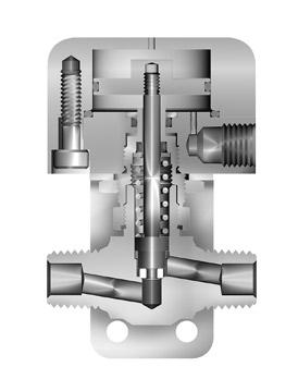
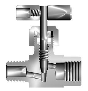
Model Shown:
Materials of Construction Manual Toggle Valve Item # Description Stainless Steel Brass 1 Body ASTM A 182 Type F316 ASTM B 283 Alloy
2 Cap ASTM A 479 Type 316 ASTM B 453 Alloy
3 Spring Stainless Steel Stainless Steel 4 Stem Seal* Fluorocarbon Rubber Fluorocarbon Rubber 5 Stem ASTM A 276 Type 316 ASTM A 276 Type 316 6 Stem Washer Stainless Steel Stainless Steel 7 Handle Nylon 6/6 Nylon 6/6 8 Handle Pin Stainless Steel Stainless Steel 9 Handle Washer Acetal Acetal 10 Panel Nut 316 Stainless Steel 316 Stainless Steel * Optional stem seal materials available - See How to Order Lubrication: Perfluorinated polyether 5 7 8 4 6 2 10 3 9 1
Toggle Valve Features Quick acting Inline and angle patterns Available with CPI™, A-LOK®, male and female NPT end connections Panel mountable Color-coded handles 316 stainless steel and brass body construction Stem seal materials –Fluorocarbon Rubber Nitrile Rubber Ethylene Propylene Rubber Highly Fluorinated Fluorocarbon Rubber Optional handle positioners and anti-lock handles 100% factory tested Manual Toggle Valve Specifications
Rating
CWP
Ratings:
PCTFE
Introduction Parker VQ Series Toggle Valves are the right combination of performance and value for manual or pneumatic on-off control in moderate pressure and temperature applications. The manual version employs a toggle handle for quick action at pressures up to 300 psig (21 bar). Compact double acting, normally closed, and normally open pneumatically actuated versions of this valve are ideal for automatic control at pressures up to 600 psig (41 bar).
4M-V4LQ-SSP Model Shown: 4A-V4LQ-BP
C37700
C34000
Manual
Pressure
at All Temperatures: 300 psig (21 bar)
Temperature
PTFE Stem Tip: -20°F to 200°F (-29°C to 93°C)
Stem Tip: -65°F to 200°F (-54°C to 93°C)
Actuated Valve Features
Available in normally open, normally closed, and double acting models Inline and angle patterns Available with CPI™, A-LOK®, male and female NPT end connections Mounting bracket standard 316 stainless steel and brass body construction Stem seal materialsFluorocarbon Rubber Nitrile Rubber Ethylene Propylene Rubber Highly Fluorinated Fluorocarbon Rubber 100% factory tested
Actuated Valve Specifications

Pressure Rating at All Temperatures:
Size VQ4 Normally Closed: 600 psig (41 bar) CWP
Size VQ6 Normally Closed: 500 psig (35 bar) CWP
Normally Open: 450 psig (31 bar) CWP
Double Acting: 450 psig (31 bar) CWP
Temperature Ratings:
PTFE Stem Tip: -20°F to 200°F (-29°C to 93°C)
PCTFE Stem Tip: -65°F to 200°F (-54°C to 93°C)
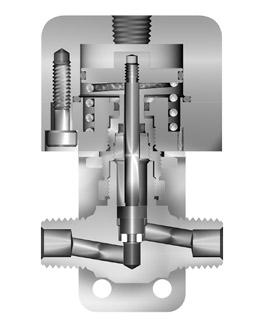
Model Shown: M6A-V4LQ-BN-11AC-SS
Materials of Construction
Description Stainless Steel Brass
Body ASTM A 182 Type F316 ASTM B 283 Alloy C37700
Cap ASTM A 479 Type 316 ASTM B 453 Alloy C34000
Spring* Stainless Steel Stainless Steel
Stem ASTM A 276 Type 316 ASTM A 276 Type 316
19
VQ
VQ 1 5 15 6 13 14 12
11 12 9 3 4 7 2 8
Parker Hannifin Corporation Instrumentation Products Division Jacksonville, AL USA http://www.parker.com/ipdus Catalog 4110-NV
Series Toggle Valves
10
#
1
2
3
4
5
6
7
8
9
10
11
12
13
14
15
*
**
***
Actuated Valve Item
Stem Seal** Fluorocarbon Rubber Fluorocarbon Rubber
Stem Washer Stainless Steel Stainless Steel
Lock Nut 316 Stainless Steel 316 Stainless Steel
Mounting Bracket Aluminum Aluminum
Actuator Base Aluminum Aluminum
Actuator Cap Aluminum Aluminum
Piston Aluminum Aluminum
Actuator Seals Fluorocarbon Rubber Fluorocarbon Rubber
Screws Stainless Steel Stainless Steel
Actuator Bushing Aluminum Aluminum
Stem Bushing*** ASTM A 479 Type 316 ASTM A 479 Type 316
Spring not used on Double Acting (11AD) models
Optional stem seal materials available - See How to Order
Stem Bushing not used on Normally Closed (11AC) models Lubrication: Perfluorinated polyether Model Shown: 4M-V4LQ-11AO-SS
Panel Hole Diameter: VQ4: 0.52 (13.2) VQ6: 0.65 (16.5)
Max. Panel Thickness: VQ4: 0.25 (6.4) VQ6: 0.35 (8.9)
VQ4 Dimensions / Flow Data
2A-V4LQ 1/8" Compression A-LOK® 0.078 2.0 0.14 0.52 1.10 27.9 1.10 27.9 0.41 10.4 0.93 23.6 2.88 73.2 1.84 46.7 1.25 31.8
2A-V4AQ 0.15 0.50
2F-V4LQ 1/8" Female NPT 0.176 4.5 0.36 0.71 0.81 20.6 0.81 20.6 0.41 10.4 0.93 23.6 2.88 73.2 1.84 46.7 1.25 31.8
2F-V4AQ 0.49 0.64
2M-V4LQ 1/8" Male NPT 0.125 3.2 0.30 0.50 0.81 20.6 0.81 20.6 0.41 10.4 0.93 23.6 2.88 73.2 1.84 46.7 1.25 31.8
2M-V4AQ 0.35 0.55
2Z-V4LQ 1/8" Compression CPI™ 0.078 2.0 0.14 0.52 1.10 27.9 1.10 27.9 0.41 10.4 0.93 23.6 2.88 73.2 1.84 46.7 1.25 31.8
2Z-V4AQ 0.15 0.50
4A-V4LQ 1/4" Compression A-LOK ® 0.176 4.5 0.36 0.71 1.15 29.2 1.15 29.2 0.41 10.4 0.93 23.6 2.88 73.2 1.84 46.7 1.25 31.8
4A-V4AQ 0.49 0.64
4M-V4LQ 1/4" Male NPT 0.176 4.5 0.36 0.71 0.94 23.9 0.94 23.9 0.41 10.4 0.93 23.6 2.88 73.2 1.84 46.7 1.25 31.8
4M-V4AQ 0.49 0.64
4Z-V4LQ 1/4" Compression CPI™ 0.176 4.5 0.36 0.71 1.15 29.2 1.15 29.2 0.41 10.4 0.93 23.6 2.88 73.2 1.84 46.7 1.25 31.8
4Z-V4AQ 0.49 0.64
6A-V4LQ 3/8" Compression A-LOK ® 0.176 4.5 0.36 0.71 1.17 29.7 1.17 29.7 0.41 10.4 0.93 23.6 2.88 73.2 1.84 46.7 1.25 31.8
6A-V4AQ 0.49 0.64
6Z-V4LQ 3/8" Compression CPI™ 0.176 4.5 0.36 0.71 1.17 29.7 1.17 29.7 0.41 10.4 0.93 23.6 2.88 73.2 1.84 46.7 1.25 31.8 6Z-V4AQ 0.49 0.64
M6A-V4LQ 6mm Compression A-LOK® 0.176 4.5 0.36 0.71 1.13 28.7 1.13 28.7 0.41 10.4 0.93 23.6 2.88 73.2 1.84 46.7 1.25 31.8
M6A-V4AQ 0.49 0.64
M6Z-V4LQ 6mm Compression CPI™ 0.176 4.5 0.36 0.71 1.13 28.7 1.13 28.7 0.41 10.4 0.93 23.6 2.88 73.2 1.84 46.7 1.25 31.8
M6Z-V4AQ 0.49 0.64
M8A-V4LQ 8mm Compression A-LOK® 0.176 4.5 0.36 0.71 1.13 28.7 1.13 28.7 0.41 10.4 0.93 23.6 2.88 73.2 1.84 46.7 1.25 31.8
M8A-V4AQ 0.49 0.64
M8Z-V4LQ 8mm Compression CPI™ 0.176 4.5 0.36 0.71 1.13 28.7 1.13 28.7 0.41 10.4 0.93 23.6 2.88 73.2 1.84 46.7 1.25 31.8
M8Z-V4AQ 0.49 0.64
* Tested in accordance with ISA S75.02. Gas flow will be choked when P1 - P2 / P1 = XT
† For CPI™ and A-LOK®, dimensions are measured with nuts in the finger tight position.
Dimensions in inches/millimeters are for reference only, subject to change.
20
Catalog 4110-NV VQ Series Toggle Valves VQ D B A G E: Open F: Closed C VQ4 Dimensions / Flow Data ( ) Denotes dimensions in millimeters
Parker Hannifin Corporation Instrumentation Products Division Jacksonville, AL USA http://www.parker.com/ipdus
Model Shown: 4M-V4AQ-EPR-SSP Model Shown: 4M-V4LQ-SSP G E: Opened F: Closed A D B C Basic Part Number End Connections Flow Data Dimensions Inlet (Port 1) Outlet (Port 2) Orifice C V X T * A† B† C D E F G Inch mm Inch mm Inch mm Inch mm Inch mm Inch mm Inch mm Inch mm
4F-V6LQ 1/4" Female NPT 0.250 6.4 0.83 0.70 1.00 25.4 1.00 25.4 0.53 13.5 1.07 27.2 3.45 87.6 2.13 54.1 1.60 40.6
4F-V6AQ 0.92 0.68
6A-V6LQ 3/8" Compression A-LOK® 0.250 6.4 0.83 0.70 1.29 32.8 1.29 32.8 0.53 13.5 1.07 27.2 3.45 87.6 2.13 54.1 1.60 40.6
6A-V6AQ 0.92 0.68
6Z-V6LQ 3/8" Compression CPI™ 0.250 6.4 0.83 0.70 1.29 32.8 1.29 32.8 0.53 13.5 1.07 27.2 3.45 87.6 2.13 54.1 1.60 40.6
6Z-V6AQ 0.92 0.68
8A-V6LQ 1/2" Compression A-LOK® 0.250 6.4 0.83 0.70 1.37 34.8 1.37 34.8 0.53 13.5 1.07 27.2 3.45 87.6 2.13 54.1 1.60 40.6
8A-V6AQ 0.92 0.68
8Z-V6LQ 1/2" Compression CPI™ 0.250 6.4 0.83 0.70 1.37 34.8 1.37 34.8 0.53 13.5 1.07 27.2 3.45 87.6 2.13 54.1 1.60 40.6
8Z-V6AQ 0.92 0.68
M10A-V6LQ 10mm Compression A-LOK® 0.250 6.4 0.83 0.70 1.30 33.0 1.30 33.0 0.53 13.5 1.07 27.2 3.45 87.6 2.13 54.1 1.60 40.6 M10A-V6AQ 0.92 0.68
M10Z-V6LQ 10mm Compression CPI™ 0.250 6.4 0.83 0.70 1.30 33.0 1.30 33.0 0.53 13.5 1.07 27.2 3.45 87.6 2.13 54.1 1.60 40.6 M10Z-V6AQ 0.92 0.68
* Tested in accordance with ISA S75.02. Gas flow will be choked when P1 - P2 / P1 = XT † For CPI™ and A-LOK®, dimensions are measured with nuts in the finger tight position.
Dimensions in inches/millimeters are for reference only, subject to change.
1.87 (47.5)
VQ4 11AC: 2.16 (54.9) VQ4 11AO/AD: 2.35 (59.7) VQ6 11AC: 2.45 (62.2) VQ6 11AO/AD: 2.64 (67.1)
21
VQ Series Toggle Valves VQ
Data
Closed
Open
Double Acting
B C
Parker Hannifin Corporation Instrumentation Products Division Jacksonville, AL USA http://www.parker.com/ipdus Catalog 4110-NV
VQ6 Dimensions / Flow
Pneumatically Actuated Valves Normally
(11AC) Normally
(11AO)
(11AD) Minimum Actuating Pressures
A Basic Part Number End Connections Flow Data Dimensions Inlet (Port 1) Outlet (Port 2) Orifice C V X T * A† B† C D E F G Inch mm Inch mm Inch mm Inch mm Inch mm Inch mm Inch mm Inch mm
1/8" Female NPT 1/8" Female NPT 1/8" Female NPT 1/8" Female NPT
Model Shown: 4F-V6AQ-11AO-B
How
The correct part number is easily derived from the following example and ordering chart. The six product characteristics required are coded as shown in the chart. The example below describes a VQ4 Series inline pattern toggle valve equipped with 1/4" CPI™ compression inlet and outlet ports, PCTFE stem tip, Nitrile rubber stem seal, and stainless steel construction with panel mounting nut.
Example 1: 4Z-V4LQK-BN-SSP
22
Catalog 4110-NV VQ Series Toggle Valves
.63 .16
Ø.20 Ø.41 .63 1.10 VQ4 Valve Mounting
Valve Mounting
Parker Hannifin Corporation Instrumentation Products Division Jacksonville, AL USA http://www.parker.com/ipdus
VQ .28 .62 .59 2.02 Ø.20 Ø.41 .62 1.37
.47 1.60
Bracket VQ6
Bracket
inches/millimeters
only,
to Order Manual Toggle Valves Dimensions in
are for reference
subject to change.
Inlet Port* Outlet Port* Valve Series Stem Tip Stem Seal Body Material 2A 4A 6A M6A 2F 4M 6Z M6Z 2M 4Z M8A 2Z M8Z V4LQ V4AQ Blank PTFE K PCTFE Blank Fluorocarbon Rubber BN Nitrile Rubber EPR Ethylene Propylene Rubber KZ Highly Fluorinated Fluorocarbon Rubber SSP Stainless Steel with Panel Nut BP Brass with Panel Nut 4F 6A 8A M10A 6Z 8Z M10Z V6LQ V6AQ *If the inlet and outlet ports are the same, eliminate the outlet port designator. Stem Tip K Valve Series V4LQ Outlet Port* Inlet Port* 4Z Stem Seal BN SSP Body Material – – –
Catalog 4110-NV
How to Order Actuated Valves
Dimensions in inches/millimeters are for reference only, subject to change.
VQ Series Toggle Valves
The correct part number is easily derived from the following example and ordering chart. The seven product characteristics required are coded as shown in the chart.
The example below describes a VQ4 Series pneumatically actuated (normally closed) angle pattern valve equipped with a 1/4" Male NPT inlet port, a 1/4" A-LOK® compression outlet port, PTFE stem tip, fluorocarbon rubber stem seal, brass construction with mounting bracket.
Example 1: 4M4A-V4AQ-11AC-B
How to Order Options
Colored Nylon Handles – Add the designator corresponding to the correct handle color as a suffix to the part number. Black is standard, W - white, B - blue, G - green, R - red, Y - yellow. Example: M10A-V6LQ-SSP-G Anti-locking Handles – Prevents the handle from locking in the open position. Add -ALH as a suffix to the part number. Example: 4M4F-V4LQ-BN-SSP-ALH
Handle Positioner – Aids in keeping the handle from rotating away from a desired position. To order, add the suffix -Q4 or -Q6 to the end of the part number. Example: 4M4F-V6LQ-EPR-SSP-Q6
Oxygen Cleaning – Add the suffix -C3 to the end of the part number to receive valves cleaned and assembled for oxygen service in accordance with Parker Specification ES8003. Example: 4A-V4AQ-EPR-SSP-C3
How to Order Maintenance Kits
Colored Nylon Handles with Handle Pin – Valve Series-Handle-Color. Example: V4Q-HANDLE-BLUE
Handle Positioners – Enables the user to position the handle in a desired location and prevents it from rotating. Examples: VQ4: VQ4-HANDLE-POSITIONER; VQ6: VQ6-HANDLE-POSITIONER
Rubber Seal and Stem Kits – Consists of one
Parker Hannifin Corporation Instrumentation Products Division Jacksonville, AL USA http://www.parker.com/ipdus
23
VQ
V4AQ Outlet Port* 4A Inlet
4M B Body
–
–Stem
Stem Tip Valve Series
Port*
Material
–
Seal Actuator Type 11AC
Inlet Port* Outlet Port* Valve Series Stem Tip Stem Seal Actuator Type Body Material 2A 4A 6A M6A 2F 4M 6Z M6Z 2M 4Z M8A 2Z M8Z V4LQ V4AQ Blank PTFE K PCTFE Blank Fluorocarbon Rubber BN
Rubber EPR
KZ
11AC
11AO
11AD
SS Stainless Steel B
4F 6A 8A M10A 6Z 8Z M10Z V6LQ V6AQ
Stem, one Rubber O-ring Stem Seal; one Packing Washer, one Handle Pin, Maintenance Instructions, Kit-Valve Series and Stem Tip-Seal Material. Examples: KIT-VQ4-BN; KIT-VQ6K-V
Nitrile
Ethylene Propylene Rubber
Highly Fluorinated Fluorocarbon Rubber
Normally Closed
Normally Opened
Double Acting
Brass
*If the inlet and outlet ports are the same, eliminate the outlet port designator.
NP6
NP6 Series Needle Valves
Introduction
Parker NP6 Needle Valves are designed with packing below the stem threads and a two-piece stem. The packing below the threads protects the flow stream from thread lubricant contamination or washout and also protects the stem threads from potential damaging effects of the media. The two-piece stem produces a non-rotating lower stem for superior, repeatable sealing and reduced packing wear.
Features
Packing below power threads protects thread lubricants from media and isolates the media from the lubricant for severe service applications
O-ring dust seal in bonnet protects stem
Specifications
Pressure Rating: 6000 psig (414 bar) CWP
Temperature Rating: PTFE Packing: -65°F to 450°F (-54°C to 232°C) PCTFE: -65°F to 350°F (-54°C to 177°C) Nitrile Rubber: -30°F to 250°F (-34°C to 121°C)
Ethylene Propylene Rubber: -70°F to 275°F (-57°C to 135°C)
Fluorocarbon Rubber: -15°F to 400°F (-26°C to 204°C) Grafoil®: -70°F to 700°F (-57°C to 371°C)
24
Catalog 4110-NV
Parker Hannifin Corporation Instrumentation Products Division Jacksonville, AL USA
http://www.parker.com/ipdus
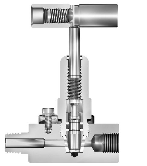
threads from external contamination Choice of two non-rotating stem types: R-Stem – All metal, blunt stem tip K-Stem – PCTFE stem tip Non rotating lower stem extends packing and valve life 316 stainless steel construction Inline and angle patterns Wide variety of US Customary and SI ports Panel mountable 100% factory tested Optional color coded handles Model Shown: 4M4F-NP6LR-SSP 8 2 1 7 5 11 9 4 10 12 6 3 Materials of Construction Item # Description Material 1 Body ASTM A 182 Type
2 Packing Nut ASTM A 479 Type 316 3 Lower Stem (R-Stem) ASTM A 276 Type 316 3 Lower Stem (K-Stem) ASTM
276 Type 316, with PCTFE 4 Upper Stem ASTM
Type 316 5 Packing Gland ASTM A 276 Type 316 6 Packing* PTFE 7 Packing Washer Stainless Steel 8 Handle** Nylon 6/6, with SS Insert 9 Handle Screw Stainless Steel 10 Packing Nut Screw Stainless Steel 11 Dust Seal Fluorocarbon Rubber 12 Panel Nut 316 Stainless Steel * Optional elastomeric stem seals and Grafoil® packing are availableSee How to Order. ** Handles for Grafoil® packed valves are aluminum T-bars. Lubrication: Perfluorinated polyether Grafoil® is a registered trademark of GrafTech International Holdings, Inc.
F316
A
A 276
*
1.38 (35.1)
A B
Max Open 2.70 (68.6) Min Close 2.56 (65.0)
.43 (10.9)
.53 (13.5)
4A-NP6LR 4A-NP6AR 1/4" Compression A-LOK® Blunt 0.177 4.5 0.60 0.50 0.67 0.39 1.20 30.5 1.20 30.5
4A-NP6LK 4A-NP6AK PCTFE 0.51 0.55 0.65 0.52 4F-NP6LR 4F-NP6AR 1/4" Female NPT Blunt 0.177 4.5 0.60 0.50 0.67 0.39 1.00 25.4 1.00 25.4
4F-NP6LK 4F-NP6AK PCTFE 0.51 0.55 0.65 0.52
4M-NP6LR 4M-NP6AR 1/4" Male NPT Blunt 0.177 4.5 0.60 0.50 0.67 0.39 1.03 26.2 1.03 26.2
4M-NP6LK 4M-NP6AK PCTFE 0.51 0.55 0.65 0.52
4Z-NP6LR 4Z-NP6AR 1/4" Compression CPI™ Blunt 0.177 4.5 0.60 0.50 0.67 0.39 1.20 30.5 1.20 30.5
4Z-NP6LK 4Z-NP6AK PCTFE 0.51 0.55 0.65 0.52
6A-NP6LR 6A-NP6AR 3/8" Compression A-LOK® Blunt 0.177 4.5 0.60 0.50 0.67 0.39 1.23 31.2 1.23 31.2
6A-NP6LK 6A-NP6AK PCTFE 0.51 0.55 0.65 0.52
6Z-NP6LK 6Z-NP6AK
6Z-NP6LR 6Z-NP6AR 3/8" Compression CPI™ Blunt 0.177 4.5 0.60 0.50 0.67 0.39 1.23 31.2 1.23 31.2
PCTFE 0.51 0.55 0.65 0.52
M6A-NP6LR M6A-NP6AR 6mm Compression A-LOK® Blunt 0.177 4.5 0.60 0.50 0.67 0.39 1.16 29.5 1.16 29.5
M6A-NP6LK M6A-NP6AK PCTFE 0.51 0.55 0.65 0.52
M6Z-NP6LK M6Z-NP6AK
M6Z-NP6LR M6Z-NP6AR 6mm Compression CPI™ Blunt 0.177 4.5 0.60 0.50 0.67 0.39 1.16 29.5 1.16 29.5
PCTFE 0.51 0.55 0.65 0.52
M8A-NP6LR M8A-NP6AR 8mm Compression A-LOK® Blunt 0.177 4.5 0.60 0.50 0.67 0.39 1.24 31.5 1.24 31.5
M8A-NP6LK M8A-NP6AK
PCTFE 0.51 0.55 0.65 0.52
M8Z-NP6LR M8Z-NP6AR 8mm Compression CPI™ Blunt 0.177 4.5 0.60 0.50 0.67 0.39 1.24 31.5 1.24 31.5
M8Z-NP6LK M8Z-NP6AK
PCTFE 0.51 0.55 0.65 0.52
* Tested in accordance with ISA S75.02. Gas flow will be choked when P1 - P2 / P1 = XT † For CPI™ and A-LOK®, dimensions are measured with nuts in the finger tight position.
Dimensions in inches/millimeters are for reference only, subject to change.
25
NP6 Series Needle Valves
/ Flow Data
( )
*
Basic Part Number End Connections Stem Type Flow Data Dimensions Inline Angle Inlet (Port 1) Outlet
Orifice Inline Angle A† B† Inch mm C V X T * C V X T * Inch mm Inch mm
Parker Hannifin Corporation Instrumentation Products Division Jacksonville, AL USA http://www.parker.com/ipdus Catalog 4110-NV
NP6 Dimensions
Panel Hole Diameter: 0.77 (19.6) Max Panel Thickness: 0.25 (6.4)
Denotes dimensions in millimeters
Note: Handle diameter for R Stem NP6 Series Valves is 1.81 (46.0) Model Shown: 4Z-NP6LK-SSP Model Shown: 4Z-NP6AR-G-SSP B 53 (13.5) 2.00 (50.8) Max Open 2.36 (59.9) Min Close 2.22 (56.4) A .43 (10.9)
(Port 2)
NP6 Series Needle Valves
How to Order
Dimensions in inches/millimeters are for reference only, subject to change.
The correct part number is easily derived from the following example and ordering chart. The six product characteristics required are coded as shown in the chart.
Example 1, below, describes an angle pattern NP6 Series needle valve equipped with 1/4" CPI™ compression inlet and outlet ports, a PCTFE tipped stem, Nitrile seals, and stainless steel construction with panel mounting nut.
Example 2, below, describes an inline pattern NP6 Series needle valve equipped with 1/4" male NPT inlet port, 1/4" female NPT outlet port, a blunt stem type, PTFE stem seal, stainless steel construction with panel mounting nut.
Example 1: 4Z-NP6AK-BN-SSP (shown in the part number blocks below)
Example 2: 4M4F-NP6LR-SSP
Parker Hannifin Corporation Instrumentation Products Division Jacksonville, AL USA http://www.parker.com/ipdus
26
Catalog 4110-NV
NP6
Inlet Port Outlet Port Valve Series Stem Type Stem Seal Body Material 4A 6A M6A 4F 6Z M6Z 4M M8A 4Z M8Z NP6L NP6A R Blunt K PCTFE Blank PTFE BN Nitrile Rubber EPR Ethylene Propylene Rubber V Fluorocarbon Rubber G Grafoil® SSP Stainless Steel with Panel Nut *If the inlet and outlet ports are the same, eliminate the outlet port designator. Stem Type K Valve Series NP6A Outlet Port* Inlet Port* 4Z Stem Seal BN SSP Body Material – – –Note: When combining seat and seal materials, the most restrictive temperature rating becomes the limiting factor on temperature range.
To determine MPa, multiply bar by 0.1
Note:
Pressure vs. Temperature Flow Characteristics
NP6 Series Needle Valves
How to Order Options
Colored Nylon Handles – Add the designator corresponding to the correct handle color as a suffix to the part number. Black is standard, W - white, B - blue, G - green, R - red, Y - yellow. Example: 4A-NP6LK-SS-G
Oxygen Cleaning – Add the suffix -C3 to the end of the part number to receive valves cleaned and assembled for oxygen service in accordance with Parker Specification ES8003. Example: M6A-NP6AK-EPR-SS-C3
Grafoil® is a registered trademark of GrafTech International Holdings, Inc.
http://www.parker.com/ipdus
27
Parker Hannifin Corporation Instrumentation Products Division Jacksonville, AL USA
Catalog 4110-NV
NP6
SN6
SN6 Series Needle Valves
Introduction
Parker compact SN6 Needle Valves provide shut-off and coarse regulation of liquids and gases utilized in process and instrumentation applications. These rugged valves are manufactured from stainless steel barstock and are integral bonnet designs with packing above the stem threads.
Specifications
Pressure Rating: R Stem: 6000 psig (414 bar) CWP K Stem: 3000 psig (207 bar) CWP
Temperature Rating:
PTFE Packing: -65°F to 450°F (-54°C to 232°C)
PCTFE Stem Tip: -65°F to 350°F (-54°C to 177°C)
Materials of Construction
Grafoil® (G) Packing: -65°F to 700°F (-54°C to 371°C)
Pressure Rating and Tubing Selection
For working pressures of A-LOK® and CPI™ tube connections, please see the Instrument Tubing Selection Guide (Bulletin 4200-TS), found in the Technical Section of the Parker Instrumentation Process Control Binder, or the Parker Instrument Tube Fitting Installation Manual (Bulletin 4200-B4).
For working pressures of valves with external or internal pipe threads, please see Catalog 4260, Instrumentation Pipe Fittings.
Parker Hannifin Corporation Instrumentation Products Division Jacksonville, AL USA http://www.parker.com/ipdus
28
Catalog 4110-NV
Features Integral bonnet design
316 stainless steel construction Choice of two stem types: R-Stem – All metal, blunt stem tip K-Stem – PCTFE stem tip Choice of PTFE or Grafoil® packing Inline and angle patterns 100% factory tested
Model Shown: 4F4M-SN6LR-SS 5 6 7 3 4 2 1 8
Item # Description Material 1 Body ASTM A 182 Type 316 2 Packing Nut ASTM A 479 Type 316 3 Packing* PTFE 4 Packing Gland ASTM A 276 Type 316 5 Packing Washer Stainless Steel 6 Stem (R-Stem) ASTM A 276 Type 316 7 Stem (K-Stem) ASTM A 276 Type 316, with PCTFE 8 Handle** Aluminum 9 Handle Screw Stainless Steel * Optional Grafoil® packing available - See How to Order. ** Handles for Grafoil® packed valves and valves with R stem types are stainless steel T-bars. Lubrication: Perfluorinated polyether. Grafoil® is a registered trademark of GrafTech International Holdings, Inc.
Shown:
Model Shown: 4M-SN6AK-SS
4A-SN6LR 4A-SN6AR 1/4" Compression A-LOK® Blunt 0.125 3.2 0.29 0.56 0.34 0.55 1.17 29.7 1.17 29.7 4A-SN6LK 4A-SN6AK PCTFE 0.23 0.63 0.27 0.58
4F-SN6LR 4F-SN6AR 1/4" Female NPT Blunt 0.125 3.2 0.29 0.56 0.34 0.55 0.94 23.9 0.94 23.9 4F-SN6LK 4F-SN6AK PCTFE 0.23 0.63 0.27 0.58
4M-SN6LR 4M-SN6AR 1/4" Male NPT Blunt 0.125 3.2 0.29 0.56 0.34 0.55 0.99 25.1 0.99 25.1 4M-SN6LK 4M-SN6AK PCTFE 0.23 0.63 0.27 0.58 4Z-SN6LR 4Z-SN6AR 1/4" Compression CPI™ Blunt 0.125 3.2 0.29 0.56 0.34 0.55 1.17 29.7 1.17 29.7 4Z-SN6LK 4Z-SN6AK PCTFE 0.23 0.63 0.27 0.58
4M4A-SN6LR 4M4A-SN6AR 1/4" Male NPT 1/4" A-LOK® Blunt 0.125 3.2 0.29 0.56 0.34 0.55 0.99 25.1 1.17 29.7 4M4A-SN6LK 4M4A-SN6AK PCTFE 0.23 0.63 0.27 0.58
4M4F-SN6LR 4M4F-SN6AR 1/4" Male NPT 1/4" Female NPT Blunt 0.125 3.2 0.29 0.56 0.34 0.55 0.99 25.1 0.94 23.9 4M4F-SN6LK 4M4F-SN6AK PCTFE 0.23 0.63 0.27 0.58 4M4Z-SN6LR 4M4Z-SN6AR 1/4" Male NPT 1/4" CPI™ Blunt 0.125 3.2 0.29 0.56 0.34 0.55 0.99 25.1 1.17 29.7 4M4Z-SN6LK 4M4Z-SN6AK PCTFE 0.23 0.63 0.27 0.58
* Tested in accordance with ISA S75.02. Gas flow will be choked when P1 - P2 / P1 = XT † For CPI™ and A-LOK®, dimensions are measured with nuts in the finger tight position.
Dimensions in inches/millimeters are for reference only, subject to change.
29
Parker Hannifin Corporation Instrumentation Products Division Jacksonville, AL USA http://www.parker.com/ipdus Catalog 4110-NV SN6 Series Needle Valves SN6 B Open 1.82 (46.2) Close 1.67 (42.4) .42 (10.7) A .40 (10.2) 1.00 ( 25.4) B A 1.38 ( 35.1) E: Open 1.98 (50.3) F: Close 1.82 (46.2) .42 (10.7) .40 (10.2)
/ Flow Data Basic Part Number End Connections Stem Type Flow Data Dimensions Inline Angle Inlet (Port 1) Outlet (Port 2) Orifice Inline Angle A† B† Inch mm C V X T * C V X T * Inch mm Inch mm
Model
4Z-SN6LR-G-SS ( ) Denotes dimensions in millimeters Dimensions
SN6
SN6 Series Needle Valves
Pressure vs. Temperature
Legend: A - Grafoil® packing with R stem B - PTFE packing with R stem C - PTFE packing with K stem.
Notes:
To determine MPa, multiply bar by 0.1 When combining seat and seal materials, the most restrictive temperature rating becomes the limiting factor on temperature range.
How to Order
Dimensions in inches/millimeters are for reference only, subject to change.
The correct part number is easily derived from the following example and ordering chart. The six product characteristics required are coded as shown in the chart.
Example 1, below, describes an SN6 valve, inline, blunt stem, 316 SS, 1/4" CPI™ tube inlet and outlet ports, and a PTFE packing.
Example 2, below, describes an SN6 valve, angle, PCTFE stem tip, 316 SS, 1/4" male pipe inlet port, 1/4" female pipe outlet port, and a PTFE packing.
Example 1: 4Z-SN6LR-SS (shown in the part number blocks below)
Example 2: 4M4F-SN6AK-SS
Parker Hannifin Corporation Instrumentation Products Division Jacksonville, AL USA http://www.parker.com/ipdus
30
Catalog 4110-NV
Note: Handles: SN6 valves with R-Stem are standard with 316 SS T-bar handles. SN6 valves with K-Stem are standard with round anodized aluminum handles, 1.00 inch diameter. SN6 valves are not panel mountable. Grafoil® is a registered trademark of GrafTech International Holdings, Inc. Size Inlet Port Outlet Port Valve Series Stem Type Packing Body Material 4 A A-LOK® (tube) Z CPI™ (tube) M Male pipe (NPT) F Female pipe (NPT) SN6L SN6A R Blunt (20°) K PCTFE Blank PTFE G Grafoil® SS 316 Stainless Steel *If the inlet and outlet ports are the same, eliminate the outlet port designator. Stem Type R Valve Series SN6L Outlet Port* Inlet Port* 4Z Packing SS Body Material – – –
31
Catalog 4110-NV SN6 Notes
Parker Hannifin Corporation Instrumentation Products Division Jacksonville, AL USA http://www.parker.com/ipdus
PV
PV Series Rising Stem Plug Valves
Introduction
Parker Rising Plug and Gauge/Root Valves are available with a variety of seat and seal materials. They are screwed bonnet designs featuring bonnet lock plates. The PV and PVG Series of valves provide a straight-through flow path in two orifice sizes. The valves utilize a non-wetted upper stem and a non-rotating lower stem in conjunction with a tapered seat for positive shut-off and long seat life, even in particulated media.
Features
Bi-directional flow
Roddable, straight through flow path
Bonnet lock plate resists accidental bonnet disengagement
Stem dust seal helps protect stem from external contamination
Inlet side optional outlet – PVG 1/4" Female NPT – PVG 1/2" Female NPT
Rugged 316 stainless steel barstock construction
Panel mounting option
Gauge port option
100% factory tested
Specifications
Pressure Rating:
Acetal Seat (DE): 6000 psig (414 bar) CWP
PEEK Seat (PK): 6000 psig (414 bar) CWP
PCTFE Seat (K): 2200 psig (152 bar) CWP
PFA Seat (PFA): 750 psig (52 bar) CWP
Temperature Rating: Seats –
Acetal: -20°F to 250°F (-29°C to 121°C)
PEEK and PFA: -20°F to 400°F (-29°C to 204°C)
PCTFE: -20°F to 200°F (-29°C to 93°C)
Stem Seals –
Nitrile Rubber (BN), Silicone Rubber (SI), and Ethylene Propylene Rubber (EPR): -20°F to 250°F (-29°C to 121°C)
Fluorocarbon Rubber (V): -20°F to 400°F (-29°C to 204°C)
Highly Fluorinated Fluorocarbon Rubber (KZ): -20°F to 200°F (-29°C to 93°C)
Flow Data
PV4: CV = 0.95; xT = 0.43; Orifice = 0.188" (4.8mm)
PV8: CV = 2.01; xT = 0.33; Orifice = 0.250" (6.4mm)
Tested in accordance with ISA S75.02. Gas flow will be choked when P1 - P2 / P1 = xT .
Materials
Parker Hannifin Corporation Instrumentation Products Division Jacksonville, AL USA http://www.parker.com/ipdus
32
Catalog 4110-NV
Model Shown: 4M4F-PV4DE-BN-SS 13 4 6 11 12 10 7 1 3 5 2 8 14 Item # Description Material 1 Body ASTM A 479 Type 316 2 Bonnet ASTM A 479 Type 316 3 Lower Stem ASTM A 276 Type 316 4 Upper Stem ASTM A 564 Type 316 5 Stem Seal* Fluorocarbon Rubber 6 Back-up Rings PTFE 7 Seat* Acetal 8 Dust Seal PTFE 9 Seat Pin (not shown) Stainless Steel 10 Lock Plate Stainless Steel 11 Lock Plate Screw Stainless Steel 12 Lock Washer Stainless Steel 13 Handle Stainless Steel 14 Handle Screw Stainless Steel * Optional elastomeric O-ring stem seals and polymer seat materials are available - See How to Order. Lubrication: Perfluorinated polyether
of Construction
Catalog 4110-NV
Model Shown: 4F-PV4DE-V-SS
Model Shown: 4F-PVG4PK-EPR-SS
4A-PV4 1/4" Compression A-LOK® 1/4" Compression A-LOK® 1.73 43.9 1.73 43.9 0.50 12.7 0.50 12.7 3.04 77.2 2.93 74.4
4F-PV4 1/4" Female NPT 1/4" Female NPT 1.13 28.7 1.13 28.7 0.50 12.7 0.50 12.7 3.04 77.2 2.93 74.4
4F-PVG4 1/4" Female NPT 1/4" Female NPT 1.75 44.5 1.13 28.7 0.50 12.7 0.50 12.7 3.04 77.2 2.93 74.4
4M4F-PV4 1/4" Male NPT 1/4" Female NPT 1.78 45.2 1.13 28.7 0.50 12.7 0.50 12.7 3.04 77.2 2.93 74.4
4Z-PV4 1/4" Compression CPI™ 1/4" Compression CPI™ 1.73 43.9 1.73 43.9 0.50 12.7 0.50 12.7 3.04 77.2 2.93 74.4
6A-PV4 3/8" Compression A-LOK® 3/8" Compression A-LOK® 1.79 45.5 1.79 45.5 0.50 12.7 0.50 12.7 3.04 77.2 2.93 74.4
6Z-PV4 3/8" Compression CPI™ 3/8" Compression CPI™ 1.79 45.5 1.79 45.5 0.50 12.7 0.50 12.7 3.04 77.2 2.93 74.4
8M4F-PV4 1/2" Male NPT 1/4" Female NPT 1.90 48.3 1.13 28.7 0.50 12.7 0.50 12.7 3.04 77.2 2.93 74.4
8M4F-PVG4 1/2" Male NPT 1/4" Female NPT 3.13 79.5 1.75 44.5 0.50 12.7 0.50 12.7 3.04 77.2 2.93 74.4
6M6F-PVG8 3/8" Male NPT 3/8" Female NPT 3.33 84.6 2.25 57.2 0.56 14.2 0.56 14.2 3.04 77.2 2.93 74.4
8A-PV8 1/2" Compression A-LOK® 1/2" Compression A-LOK® 1.91 48.5 1.91 48.5 0.56 14.2 0.56 14.2 3.04 77.2 2.93 74.4
8F-PV8 1/2" Female NPT 1/2" Female NPT 1.33 33.8 1.33 33.8 0.56 14.2 0.56 14.2 3.04 77.2 2.93 74.4
8M8F-PV8 1/2" Male NPT 1/2" Female NPT 2.17 55.1 1.33 33.8 0.56 14.2 0.56 14.2 3.04 77.2 2.93 74.4
8M8F-PVG8 1/2" Male NPT 1/2" Female NPT 3.33 84.6 2.25 57.2 0.56 14.2 0.56 14.2 3.04 77.2 2.93 74.4
8Z-PV8 1/2" Compression CPI™ 1/2" Compression CPI™ 1.91 48.5 1.91 48.5 0.56 14.2 0.56 14.2 3.04 77.2 2.93 74.4
12M8F-PV8 3/4" Male NPT 1/2" Female NPT 2.17 55.1 1.33 25.4 0.56 14.2 0.56 14.2 3.04 77.2 2.93 74.4
† For CPI™ and A-LOK®, dimensions are measured with nuts in the finger tight position.
Dimensions in inches/millimeters are for reference only, subject to change.
Parker Hannifin Corporation Instrumentation Products Division Jacksonville, AL USA http://www.parker.com/ipdus
33
PV
Plug
B A
E: Open F: Close C D B A E: Open F: Close C D
Series Rising Stem
Valves PV
2.20 (55.9)
2.20 (55.9)
Dimensions ( ) Denotes dimensions in millimeters Basic Part Number End Connection Dimensions Inlet (Port 1) Outlet (Port 2) A† B† C D E F Inch mm Inch mm Inch mm Inch mm Inch mm Inch mm
PV
PV Series Rising Stem Plug Valves
How to Order
Dimensions in inches/millimeters are for reference only, subject to change.
The correct part number is easily derived from the following example and ordering chart. The six product characteristics required are coded as shown in the chart.
Example 1, below, describes a PV4 Series rising stem plug valve equipped with 1/4" CPI™ compression inlet and outlet ports, a PCTFE seat, Nitrile stem seals, and stainless steel construction.
Example 2, below, describes a PVG4 Series rising stem plug valve with 1/4" gauge ports equipped with a 1/4" Male NPT inlet port and 1/4" Female NPT outlet port, an acetal seat, fluorocarbon stem seals, and stainless steel construction with panel mounting option.
Example 1: 4Z-PV4K-BN-SS (shown in the part number blocks below)
Example 2: 4M-PVG4DE-V-SSP
Parker Hannifin Corporation Instrumentation Products Division Jacksonville, AL USA http://www.parker.com/ipdus
34
Catalog 4110-NV
Inlet Port* Outlet Port* Valve Series Seat Type Stem Seal Body Material 4A 4M 6A 8M 4F 4Z 6Z PV4 PVG4 DE Acetal K PCTFE PK PEEK PFA PFA V Fluorocarbon Rubber BN Nitrile Rubber SI Silicone Rubber EPR Ethylene Propylene Rubber KZ Highly Fluorinated Fluorocarbon Rubber SS Stainless Steel SSP Stainless Steel with Panel Mounting Option 6M 8A 8Z 6F 8F 12M PV8 PVG8 *If the inlet and outlet ports are the same, eliminate the outlet port designator. Seat Type K Valve Series PV4 Outlet Port* Inlet Port* 4Z Stem Seal Material BN SS Body Material – – –Pressure vs. Temperature
Flow Characteristics
35
Catalog 4110-NV PV Notes
Parker Hannifin Corporation Instrumentation Products Division Jacksonville, AL USA http://www.parker.com/ipdus
36
Catalog 4110-NV
Series Needle Valves
Pressure Valves
Parker Hannifin Corporation Instrumentation Products Division Jacksonville, AL USA http://www.parker.com/ipdus
MPN
MPN Medium
MPN series valves are designed for multi-turn control of media regulation and shutoff
psi.
packing materials
available for application temperatures
service design features,
packing
Materials of Construction 1 Soc Set Screw Steel 2 Handle Aluminum 3 Upper Stem Assembly 17-4PH 4 Packing Gland 316SS 5 Locking Device 300 SER. SS 6 10-32 X 1/4 Fill HD SCR. 300 SER. SS 7 Stem Pin 304SS 8 Top Packing Washer 416SS 9 Packing PTFE 10 Bottom Packing Washer 316SS 11 Lower Stem 17-4PH-H900 12 Body 316SS Item # Description Material Medium Pressure Valve Connection Types MP7 Parker MPI™ (Medium Pressure Inverted) To 15,000 PSI F Female NPT To 15,000 PSI MF Cone & Thread (Medium Pressure Female) To 20,000 PSI
MPN Series Valves Parker
up to 20,000
Additional
are
from -300° to +800° F. Standard critical
such as the
below the thread and the non-rotating lower stem ensure longer valve life in rugged applications.
How to Order MPN Series Valves
Dimensions in inches/millimeters are for reference only, subject to change. The correct part number is easily derived from the following example and ordering chart. The nine product characteristics required are coded as shown in the chart. The following example describes an MPN Series needle valve with 1/4" MPI connections, 2 way angle flow path, blunt stem, PTFE packing, stainless steel body and the option for over critical service. Example: 4MP7-MPNAB-T-SS-OC
Connection Type F Female Pipe MP7 Parker MPI™ MF Female Cone & Thread W Tube Socket Weld PSW Pipe Socket Weld
Valve Series MPN
Inline A 2-Way Angle X***I 3-Way 2-Pressure Connections X***D 3-Way 2-Stem Connection A***R 2-Way Angle Valve (Replaceable Seat) *** Needle Type Inserted Here
How to Order Options
Body Material
Options (See Below) OC Over Critical HYD Hydrogen Compatible LT Low Temperature
Over Critical – add the suffix -OC to the end of the part number to specify over critical service.
Hydrogen Service – add the suffix -HYD to the end of the part number for a valve suitable for hydrogen service. Low Temperature – add the suffix -LT to the end of the part number for low temperature service.
Parker Hannifin Corporation Instrumentation Products Division Jacksonville, AL USA http://www.parker.com/ipdus
37
Catalog 4110-NV MPN Series Needle Valves MPN
2* 4
Inlet / Outlet Connection Size
6 8 9** 12 16 1/8" 1/4" 3/8" 1/2" 9/16" 3/4" 1" * Female Pipe Only ** MP7 and MF only MP7 4 SS – –
OC Options High Flow Valve
A
– T Packing Material –Packing
T
B
Type
MPN B
Material
PTFE G Graphoil® High Flow Blank Standard Flow H High Flow Stem Type
Blunt R Regulating Valve Type L 2-Way
SS Stainless Steel Grafoil® is a registered trademark of GrafTech International Holdings, Inc. Valve Series Connection Type Inlet/Outlet Connection Size Stem Type Body Material
MPN
MPN Series Needle Valves
Two Way Inline Valves
Panel Hole Sizes
Medium Pressure Needle Valve Panel Mount
Valve Size B
Screw Size D A
4 & 6 1.25 .219 10 - 32 .75 8 & 9 1.375 .219 10 - 32 1.00 12 1.75 .219 10 - 32 1.19 16 2.50 .219 10 - 32 1.63
Tubing Inches
Size
1/4" O.D. 4MP7-MPNLB-T-SS 15,000 1/4" MPI 0.125 4.50 2.50 0.50 0.94 2.13 0.38 1.25 0.22 1.00 3/8" O.D. 6MP7-MPNLB-T-SS 15,000 3/8" MPI 0.203 4.50 2.50 0.50 0.94 2.13 0.38 1.25 0.22 1.00 1/2" O.D. 8MP7-MPNLB-T-SS 15,000 1/2" MPI 0.313 6.26 3.00 0.63 1.25 3.00 0.50 1.38 0.34 1.38 9/16" O.D. 9MP7-MPNLB-T-SS 15,000 9/16" MPI 0.313 6.26 3.00 0.63 1.25 3.00 0.50 1.38 0.34 1.38 3/4" O.D. 12MP7-MPNLB-T-SS 15,000 3/4" MPI 0.438 7.00 4.13 0.75 1.50 3.75 0.63 1.75 0.44 1.75 3/4" O.D. 12MP7-MPNLBH-T-SS 10,000 3/4" MPI 0.516 7.00 4.13 0.75 1.50 3.75 0.63 1.75 0.44 1.75 1" O.D. 16MP7-MPNLB-T-SS 12,500 1" MPI 0.563 8.42 4.13 0.88 1.81 4.63 1.13 2.50 0.56 1.75
Connection Inches
Pipe Size Parker Part No. PSI Female NPT Orifice A B C D E F G H Th'k 1/8" NPT 2F-MPNLB-T-SS 15,000 1/8" 0.203 4.38 2.00 0.38 0.81 2.00 0.38 1.25 0.22 0.75 1/4" NPT 4F-MPNLB-T-SS 15,000 1/4" 0.203 4.38 2.00 0.38 0.81 2.00 0.38 1.25 0.22 0.75 3/8" NPT 6F-MPNLB-T-SS 15,000 3/8" 0.312 6.13 2.50 0.50 1.13 2.88 0.50 1.38 0.34 1.00 1/2" NPT 8F-MPNLB-T-SS 15,000 1/2" 0.312 6.38 2.63 0.75 1.38 3.13 0.50 1.38 0.34 1.50 3/4" NPT 12F-MPNLB-T-SS 10,000 3/4" 0.687 8.50 4.13 0.88 1.81 4.63 1.13 2.50 0.56 1.75 1" NPT 16F-MPNLB-T-SS 10,000 1" 0.687 8.50 4.13 0.88 1.81 4.63 1.13 2.50 0.56 1.75
Dimensions in inches/millimeters are for reference only, subject to change.
Parker Hannifin Corporation Instrumentation Products Division Jacksonville, AL USA http://www.parker.com/ipdus
38
Catalog 4110-NV
Parker Part No. PSI Connection Orifice A B C D E F G H Th'k
Two Way Angle Valves
MPN Series Needle Valves
Panel Hole Sizes
Medium Pressure Needle Valve Panel Mount
Valve Size B
Screw Size D A
4 & 6 1.25 .219 10 - 32 .75
8 & 9 1.375 .219 10 - 32 1.00 12 1.75 .219 10 - 32 1.19 16 2.50 .219 10 - 32 1.63
Inches
1/4" O.D. 4MP7-MPNAB-T-SS 15,000 1/4" MPI 0.125 5.02 2.50 - 1.38 2.57 0.38 1.25 0.22 1.00 3/8" O.D. 6MP7-MPNAB-T-SS 15,000 3/8" MPI 0.203 5.02 2.50 - 1.38 2.57 0.38 1.25 0.22 1.00 1/2" O.D. 8MP7-MPNAB-T-SS 15,000 1/2" MPI 0.313 6.84 3.00 - 1.83 3.58 0.50 1.38 0.34 1.38 9/16" O.D. 9MP7-MPNAB-T-SS 15,000 9/16 MPI 0.313 6.84 3.00 - 1.83 3.58 0.50 1.38 0.34 1.38 3/4" O.D. 12MP7-MPNAB-T-SS 15,000 3/4" MPI 0.438 7.50 3.00 - 2.00 4.25 0.63 1.75 0.44 1.38 3/4" O.D. 12MP7-MPNABH-T-SS 10,000 3/4" MPI 0.516 7.50 3.00 - 2.00 4.25 0.63 1.75 0.44 1.38 1" O.D. 16MP7-MPNAB-T-SS 12,500 1" MPI 0.563 9.38 4.13 - 2.56 5.44 1.13 2.50 0.56 1.75 1" O.D. 16MP7-MPNABH-T-SS 10,000 1" MPI 0.688 9.38 4.13 - 2.56 5.44 1.13 2.50 0.56 1.75
Connection Inches
Pipe Size Parker Part No. PSI Female NPT Orifice A B C D E F G H Th'k 1/8" NPT 2F-MPNAB-T-SS 15,000 1/8" NPTF 0.203 4.81 2.00 - 1.25 2.44 0.38 1.25 0.22 0.75 1/4" NPT 4F-MPNAB-T-SS 15,000 1/4" NPTF 0.203 4.81 2.00 - 1.25 2.44 0.38 1.25 0.22 0.75 3/8" NPT 6F-MPNAB-T-SS 15,000 3/8" NPTF 0.312 6.50 2.50 - 1.50 3.25 0.50 1.38 0.34 1.00 1/2" NPT 8F-MPNAB-T-SS 15,000 1/2" NPTF 0.312 6.50 2.63 - 1.50 3.25 0.50 1.38 0.34 1.50 3/4" NPT 12F-MPNAB-T-SS 10,000 3/4" NPTF 0.687 9.00 4.13 - 2.31 5.13 1.13 2.50 0.56 1.75 1" NPT 16F-MPNAB-T-SS 10,000 1" NPTF 0.687 9.00 4.13 - 2.31 5.13 1.13 2.50 0.56 1.75
Dimensions in inches/millimeters are for reference only, subject to change.
39
Parker Hannifin Corporation Instrumentation Products Division Jacksonville, AL USA http://www.parker.com/ipdus
Catalog 4110-NV
MPN
Tubing Parker Part No. PSI Connection Orifice A B C D E F G H Th'k
Panel Hole Sizes
Medium Pressure Needle Valve Panel Mount
Valve Size B
Screw Size D A
4 & 6 1.25 .219 10 - 32 .75 8 & 9 1.375 .219 10 - 32 1.00 12 1.75 .219 10 - 32 1.19 16 2.50 .219 10 - 32 1.63
Inches
Tubing Parker Part No. PSI Connection Orifice A B C D E F G H Th'k 1/4" O.D. 4MP7-MPNXBI-T-SS 15,000 1/4" MPI 0.125 5.21 2.50 1.21 1.65 2.84 0.38 1.25 0.22 1.00 3/8" O.D. 6MP7-MPNXBI-T-SS 15,000 3/8" MPI 0.203 5.21 2.50 1.21 1.65 2.84 0.38 1.25 0.22 1.00 1/2" O.D. 8MP7-MPNXBI-T-SS 12,500 1/2" MPI 0.313 7.09 3.00 1.50 2.12 3.88 0.50 1.38 0.34 1.38 9/16" O.D. 9MP7-MPNXBI-T-SS 12,500 9/16" MPI 0.313 7.09 3.00 1.50 2.12 3.88 0.50 1.38 0.34 1.38 3/4" O.D. 12MP7-MPNXBI-T-SS 15,000 3/4" MPI 0.438 7.88 3.00 2.63 2.38 4.63 0.63 1.75 0.44 1.38 3/4" O.D. 12MP7-MPNXBIH-T-SS 10,000 3/4" MPI 0.516 7.88 3.00 2.63 2.38 4.63 0.63 1.75 0.44 1.38 1" O.D. 16MP7-MPNXBI-T-SS 12,500 1" MPI 0.563 9.75 4.13 2.13 3.06 5.88 1.13 2.50 0.56 1.75 1" O.D. 16MP7-MPNXBIH-T-SS 10,000 1" MPI 0.688 9.75 4.13 2.13 3.06 5.88 1.13 2.50 0.56 1.75
Dimensions in inches/millimeters are for reference only, subject to change.
Panel Hole Sizes
Medium Pressure Needle Valve Panel Mount
Valve Size B
Screw Size D A
4 & 6 1.25 .219 10 - 32 .75 8 & 9 1.375 .219 10 - 32 1.00 12 1.75 .219 10 - 32 1.19 16 2.50 .219 10 - 32 1.63
1.38
1.38 3/4" O.D. 12MP7-MPNXBO-T-SS 15,000 3/4" MPI 0.438 7.50 3.00 2.00 2.00 4.25 0.63 1.75 0.44 1.38 3/4" O.D. 12MP7-MPNXBOH-T-SS 10,000 3/4" MPI 0.516 7.50 3.00 2.00 2.00 4.25 0.63 1.75 0.44 1.38 1" O.D. 16MP7-MPNXBO-T-SS 12,500 1" MPI 0.563 9.38 4.13 2.63 2.63 5.44 1.13 2.50 0.56 1.75 1" O.D. 16MP7-MPNXBOH-T-SS 10,000 1" MPI 0.688 9.38 4.13 2.63 2.63 5.44 1.13 2.50 0.56 1.75
Dimensions in inches/millimeters are for reference only, subject to change.
40
http://www.parker.com/ipdus Catalog 4110-NV MPN Series Needle Valves MPN Three Way/Two Pressure Connections Three Way/One Pressure Connection Inches Tubing Parker Part No. PSI Connection Orifice A B C D E F G H Th'k 1/4" O.D. 4MP7-MPNXBO-T-SS 15,000 1/4" MPI 0.125 5.02 2.50 1.38
3/8" O.D. 6MP7-MPNXBO-T-SS 15,000 3/8" MPI 0.203 5.02 2.50 1.38
1/2" O.D. 8MP7-MPNXBO-T-SS 15,000 1/2" MPI 0.313 6.84 3.00
9/16" O.D. 9MP7-MPNXBO-T-SS 15,000 9/16" MPI 0.313 6.84 3.00
Parker Hannifin Corporation Instrumentation Products Division Jacksonville, AL USA
1.38 2.57 0.38 1.25 0.22 1.00
1.38 2.57 0.38 1.25 0.22 1.00
1.88 1.88 3.63 0.50 1.38 0.34 1.38
1.88 1.88 3.63 0.50
0.34
Catalog 4110-NV
Three Way/Two Stem Connection
MPN Series Needle Valves
Panel Hole Sizes
Medium Pressure Needle Valve Panel Mount
Valve Size B
Screw Size D A
4 & 6 1.25 .219 10 - 32 .75 8 & 9 1.375 .219 10 - 32 1.00 12 1.75 .219 10 - 32 1.19 16 2.50 .219 10 - 32 1.63
Inches
Tubing Parker Part No. PSI Connection Orifice A B C D E F G H Th'k
1/4" O.D. 4MP7-MPNXBD-T-SS 15,000 1/4" MPI 0.125 5.75 2.50 1.70 1.19 3.38 0.38 1.25 0.22 1.00 3/8" O.D. 6MP7-MPNXBD-T-SS 15,000 3/8" MPI 0.203 5.75 2.50 1.70 1.19 3.38 0.38 1.25 0.22 1.00 1/2" O.D. 8MP7-MPNXBD-T-SS 15,000 1/2" MPI 0.313 8.38 3.00 2.56 1.75 5.13 0.50 1.38 0.34 1.38 9/16" O.D. 9MP7-MPNXBD-T-SS 15,000 9/16" MPI 0.313 8.38 3.00 2.56 1.75 5.13 0.50 1.38 0.34 1.38 3/4" O.D. 12MP7-MPNXBD-T-SS 15,000 3/4" MPI 0.438 9.75 3.00 3.25 2.25 6.50 0.63 1.75 0.44 1.38 3/4" O.D. 12MP7-MPNXBDH-T-SS 10,000 3/4" MPI 0.516 9.75 3.00 3.25 2.25 6.50 0.63 1.75 0.44 1.38 1" O.D. 16MP7-MPNXBD-T-SS 12,500 1" MPI 0.563 12.19 4.13 4.13 2.81 8.25 1.13 2.50 0.56 1.75 1" O.D. 16MP7-MPNXBDH-T-SS 10,000 1" MPI 0.688 12.19 4.13 4.13 2.81 8.25 1.13 2.50 0.56 1.75
Two Way Angle Valves (Replaceable Seat)
Dimensions in inches/millimeters are for reference only, subject to change.
Panel Hole Sizes
Medium Pressure Needle Valve Panel Mount
Valve Size B
Screw Size D A
4 & 6 1.25 .219 10 - 32 .75 8 & 9 1.375 .219 10 - 32 1.00 12 1.75 .219 10 - 32 1.19 16 2.50 .219 10 - 32 1.63
Inches
B C
Dimensions in inches/millimeters are for reference only, subject to change.
41
Parker Hannifin Corporation Instrumentation Products Division Jacksonville, AL USA http://www.parker.com/ipdus MPN
Tubing Parker Part No. PSI Connection Orifice A
D E F G H Th'k
1/4" O.D. 4MP7-MPNABR-T-SS 15,000 1/4" MPI 0.125 5.87 2.50 - 1.38 2.57 0.38 1.25 0.22 1.00 3/8" O.D. 6MP7-MPNABR-T-SS 15,000 3/8" MPI 0.203 5.87 2.50 - 1.38 2.57 0.38 1.25 0.22 1.00 1/2" O.D. 8MP7-MPNABR-T-SS 15,000 1/2" MPI 0.313 8.25 3.00 - 2.00 3.63 0.50 1.38 0.34 1.38 9/16" O.D. 9MP7-MPNABR-T-SS 15,000 9/16" MPI 0.313 8.25 3.00 - 2.00 3.63 0.50 1.38 0.34 1.38 3/4" O.D. 12MP7-MPNABR-T-SS 15,000 3/4" MPI 0.438 8.88 3.00 - 2.00 4.25 0.63 1.75 0.44 1.38 3/4" O.D. 12MP7-MPNABRH-T-SS 10,000 3/4" MPI 0.516 8.88 3.00 - 2.00 4.25 0.63 1.75 0.44 1.38 1" O.D. 16MP7-MPNABR-T-SS 12,500 1" MPI 0.563 11.13 4.13 - 2.56 5.44 1.13 2.50 0.56 1.75 1" O.D. 16MP7-MPNABRH-T-SS 10,000 1" MPI 0.688 11.13 4.13 - 2.56 5.44 1.13 2.50 0.56 1.75
MPN
MPN Series Needle Valves
Over Critical Valves
Size Parker Part No. PSI Connection Orifice A B C D E F G H Th'k
1/4" O.D. 4MP7-MPNLB-G-SS-OC 10,000 4MP7 0.125 4.50 2.50 0.50 0.94 2.13 0.38 1.25 0.22 0.75 3/8" O.D. 6MP7-MPNLB-G-SS-OC 10,000 6MP7 0.203 4.50 2.50 0.50 0.94 2.13 0.38 1.25 0.22 0.75 1/2" O.D. 8MP7-MPNLB-G-SS-OC 10,000 8MP7 0.313 6.26 3.00 0.63 1.25 3.00 0.50 1.38 0.34 1.00 9/16" O.D. 9MP7-MPNLB-G-SS-OC 10,000 9MP7 0.313 6.26 3.00 0.63 1.25 3.00 0.50 1.38 0.34 1.00 3/4" O.D. 12MP7-MPNLB-G-SS-OC 10,000 12MP7 0.438 7.00 3.00 0.75 1.50 3.75 0.63 1.75 0.44 1.38 1" O.D. 16MP7-MPNLB-G-SS-OC 10,000 16MP7 0.563 8.42 4.13 0.88 1.81 4.63 1.13 2.5 0.56 1.75 1/8" NPT 2F-MPNLB-G-SS-OC 10,000 1/8" NPTF 0.203 4.38 2.00 0.38 0.81 2.00 0.38 1.25 0.22 0.75 1/4" NPT 4F-MPNLB-G-SS-OC 10,000 1/4" NPTF 0.203 4.38 2.00 0.38 0.81 2.00 0.38 1.25 0.22 0.75 3/8" NPT 6F-MPNLB-G-SS-OC 10,000 3/8" NPTF 0.312 6.13 2.5 0.50 1.13 2.88 0.50 1.38 0.34 1.00 1/2" NPT 8F-MPNLB-G-SS-OC 10,000 1/2" NPTF 0.312 6.38 2.63 0.75 1.38 3.13 0.50 1.38 0.34 1.50 3/4" NPT 12F-MPNLB-G-SS-OC 10,000 3/4" NPTF 0.687 8.50 4.13 0.88 1.81 4.63 1.13 2.5 0.56 1.75 1" NPT 16F-MPNLB-G-SS-OC 10,000 1" NPTF 0.687 8.50 4.13 0.88 1.81 4.63 1.13 2.5 0.56 1.75
http://www.parker.com/ipdus
42
Catalog 4110-NV
Parker Hannifin Corporation Instrumentation Products Division Jacksonville, AL USA
Item # Description Material 1 Set Screw 316SS 2 Handle 303SS 3 Upper Stem Assembly 416SS 4 Packing Gland 316SS 5 Locking Device 304SS 6 Lock Screw 304SS 7 Stem Pin 304SS 8 Top Packing Washer 416SS 9 Packing Grafoil® 10 Bottom Pack Washer 316SS 11 Lower Stem 316SS 12 Body 316SS
vs. Temperature
Materials of Construction Grafoil® is a registered trademark of GrafTech International Holdings, Inc. Dimensions in inches/millimeters are for reference only, subject to change.
Pressure
Chart
43 Parker Hannifin Corporation Instrumentation Products Division Jacksonville, AL USA http://www.parker.com/ipdus Catalog 4110-NV MPN Series Needle Valves MPN Bleed Valve Materials of Construction Gauge Valve Materials of Construction 3 2 4 5 6 1 9T7-MPBV-V-SS 15,000 9/16" Tube Stub 9HM-MPBV-V-SS 30,000 9/16" High Pressure Male Parker Part No. PSI Connection 3 5 7 4 2 9 8 6 10 1 9MP7-MPGV-V-SS 15,000 9/16" MPI™ 9HF-MPGV-V-SS 30,000 9/16" High Pressure Female Parker Part No. PSI Connection *Optional Seal Materials KZ Highly Fluorinated Fluorocarbon Rubber BN Nitrile Rubber EPR Ethylene Propylene Rubber Example: 9T7-MPBV-KZ-SS Item # Qty Description Material 1 1 Soc Set Screw Steel 2 1 Handle Aluminum 3 1 Stem Assembly 17-4PH 4 1 Packing Gland 316SS 5 1 Locking Device 300 Ser. SS 6 1 10-32 x 1/4 Fill Hd Scr. 300 Ser. SS 7 1 Top Packing Washer 416SS 8 1 Packing Fluorocarbon Rubber 9 1 Bottom Packing Washer 316SS 10 1 Body 316SS Item # Qty Description Material 1 1 Soc Set Screw 300 Ser. SS 2 1 Handle Aluminum 3 1 Stem 17-4PH-H900 4 2 Rolling Pin 420SS 5 1 O-Ring Fluorocarbon Rubber* 6 1 Body 316SS
Cyl & Acc
Cylinders & Accessories
Sample Cylinders
Parker stainless steel sample cylinders provide safe containment for storage and transportation of both liquids and gases. These cylinders are DOT rated to 1800 psig (124 bar) at 70°F (21°C). Applications include hydrocarbon sampling in refineries, gas sampling in chromatography, and condensate sampling in fossil fuel and nuclear power plants.
ANSI/ASME B1.20.1 internal pipe threads are machined into both ends of each cylinder to engage external pipe connections of Parker valves, rupture disc units, or fittings.
Stainless Steel Cylinders
Stainless steel sample cylinders are hot spun from seamless Type 316 tubing for integrity and corrosion resistance. The process provides a smooth internal flow transition through the neck to minimize pockets which can trap previous samples. Without the need for welding, the interior surface is free of any imperfections. As a result, less contamination will adhere to the interior surface when the cylinder is cleaned.
Specifications
Pressure and temperature rating: 1800 psig (124 bar) -58°F to 450°F (-50°C to 232°C)
DOT-3E 1800: 75, 150, 300, and 500cc with 1/4" NPT threads
DOT-3A 1800: 1000 and 2250cc with 1/4" NPT threads
DOT-3A 1800: 3785cc (1 gallon) with 1/2" NPT threads
http://www.parker.com/ipdus
44
Catalog 4110-NV
Parker Hannifin Corporation Instrumentation Products Division Jacksonville, AL USA
4F-SC75D-SS 4F-SC150D-SS 4F-SC300D-SS 4F-SC500D-SS 4F-SC1000D-SS 4F-SC2250D-SS-WC 8F-SC1GD-SS-WC
Catalog 4110-NV
Cylinder Design, Production and Testing
Cylinders & Accessories
The design, manufacture and testing of steel sample cylinders is regulated by the US government in 49 CFR, Paragraphs 178.36 Specification 3A; seamless steel cylinders and 178.42 Specification 3E; seamless steel cylinders. Specification 3A deals with cylinders not over 1,000 pounds (455 kg) water capacity and Specification 3E is for cylinders having an outside diameter no greater than 2 inches (51 mm), with a length less than 2 feet (61 cm). Service pressure is limited to 1,800 psi (124 bar) for Parker Sample Cylinders.
The above regulations control all aspects of the design and production of sample cylinders. Material physical properties and chemical characteristics are controlled. Each cylinder must be hydrostatically tested between 3,000 and 4,500 psi (207 and 310 bar). In addition, one cylinder out of each lot of 500 or less must be subjected to a burst test and result in a safety factor on burst pressure of 3.3 minimum.
All cylinder tests must be inspected and verified by an independent inspection agency, and all test reports must be maintained for fifteen years. Each cylinder must also be marked and packaged in accordance with 49 CFR.
Note: DOT-3A 1800 cylinders must also be re-tested every five years at 3,000 psig (207 bar).
How
316
DOT-3E 1800 75 4F-SC75S-SS 4F-SC75D-SS 4.88 124 1.50 38 0.60 0.27 150 4F-SC150S-SS 4F-SC150D-SS 8.13 206 1.50 38 1.00 0.45 300 4F-SC300S-SS 4F-SC300D-SS 9.25 235 2.00 51 1.80 0.82 500 4F-SC500S-SS 4F-SC500D-SS 13.88 352 2.00 51 2.50 1.14
DOT-3A 1800 1000 4F-SC1000S-SS 4F-SC1000D-SS 9.50 241 4.00 102 7.50 3.41 2250 4F-SC2250S-SS-WC 4F-SC2250D-SS-WC 16.5** 419** 4.00 102 12.00 5.45 3785 8F-SC1GS-SS-WC 8F-SC1GD-SS-WC 25.5** 648** 4.00 102 17.80 8.09
* A stainless steel pipe plug is supplied for use in one end of the cylinder when a single-ended cylinder is ordered.
**Includes threaded neck rings and caps. Add 6-1/4" (159mm) to each end to include cap lengths.
Dimensions in inches/millimeters are for reference only, subject to change.
Parker Hannifin Corporation Instrumentation Products Division Jacksonville, AL USA http://www.parker.com/ipdus
45
Cyl & Acc
DOT Min. Internal Volume (cc) Part Number Dimensions (ref.) Length Outside Diameter Approx.Weight Single-End* Double-End inch mm inch mm lb. kg
to Order / Dimensions Material
Stainless Steel
Cyl & Acc
Cylinders
V4LC Series Miniature Needle Valves
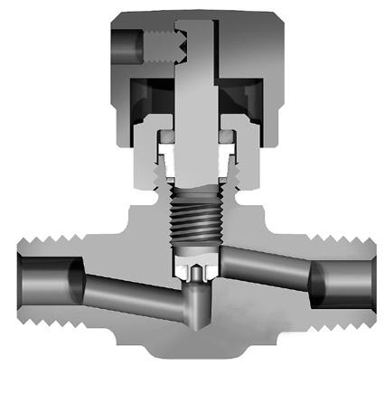
Features
Stainless steel construction Tapered bore PTFE packing Optional R stem (all metal, blunt tip) or K stem (PCTFE stem tip) Knurled aluminum handle Optional stem packings
Specifications
Pressure Rating: 5000 psig CWP (345 bar)
Temperature Rating:
With PTFE packings –R stem: -65°F to 450°F (-54°C to 232°C) K stem: -65°F to 350°F (-54°C to 177°C)
With Nitrile rubber packing –-30°F to 250°F (-34°C to 121°C)
With Fluorocarbon rubber packings –-15°F to 400°F (-26°C to 204°C)
With Ethylene propylene rubber packing –-70°F to 275°F (-21°C to 135°C)
With Neoprene rubber packing –-65°F to 250°F (-54°C to 121°C)
Ports: ANSI/ASME B1.20.1; 1/4" external pipe threads
Orifice: 0.176" (4.5mm)
How to Order
46
Catalog 4110-NV
Parker Hannifin Corporation Instrumentation Products Division Jacksonville, AL USA http://www.parker.com/ipdus
& Accessories
3 1 2 4 5 6 7 8 Item # Description Material 1 Body ASTM A 182 Type F316 2 Packing Nut ASTM A 479 Type 316 3 Handle ASTM B 211 Alloy A92024 4 Lower Packing Washer 316 Stainless Steel 5 Handle Set Screw 316 Stainless Steel 6 Packing PTFE 7 R Stem ASTM A 276 Type 316 7 K Stem ASTM A 276 Type 316 with PCTFE 8 Upper Packing Washer Commercial Brass * Optional elastomeric O-ring stem seals and polymer seat materials are available - See How to Order. Lubrication: Perfluorinated polyether
Dimensions in inches/millimeters are for reference only, subject to change. The
part
characteristics
Example 1
Example 2
Example
Examples: 1: 4M-VL4CK-SS (shown in the part number blocks below) 2: 4M-VL4CR-SS 3: 4M-VL4CK-BN-SS Stem Type K Valve Series VL4C Inlet Port 4M Optional Stem* BN SS Body Material – – –Materials of Construction Model Shown: 4M-V4LCK-SS () Denotes dimensions in millimeters Inlet Port Valve Series Stem Type Optional Elastomeric Stem Packaging Body Material 4M VL4C K PCTFE R All metal, blunt tip V Fluorocarbon Rubber BN Nitrile Rubber EPR Ethylene Propylene Rubber NE Neoprene Rubber SS Stainless Steel
correct
number is easily derived from the following example and ordering chart. The five product
required are coded as shown in the chart.
describes a needle valve with a K stem.
describes a needle valve with a R stem.
3 describes a needle valve with a K stem and optional elastomeric stem packaging of Nitrile rubber.
Catalog 4110-NV
Rupture Disc Units
Features
Designed for direct engagement to stainless steel sample cylinders for protection against overpressure.
Pre-bulged 316 stainless steel rupture disc minimizes fragmentation upon burst.
Pre-bulged disk provides close tolerance of the actual burst pressure.
Specifications
Pressure Rating*: 1800 psig at 70°F (124 bar at 21°C)
Temperature Rating:
With standard PTFE gasket –-65°F to 150°F (-54°C to 66°C)
With optional metal gasket–-65°F to 400°F (-54°C to 204°C)
*Note: Contact your Parker Distributor for availability of optional rupture disc pressures from 160 psig to 5000 psig (11 bar to 345 bar).
Pressure vs. Temperature
&
Model Shown: 4M4F-RV6L-18-SS
Materials of Construction
Part Description Material
Body ASTM A 182 Type F316
Plug ASTM A 479 Type 316
Ruptured Disk AISI Type 316*
Gasket PTFE or 316 Stainless Steel with PTFE Coating
*NOTE: Ruptured disk material will be aluminum for pressures below 1260 psig (86 bar).
Precautions
1. Ensure the minimum burst pressure rating of the Rupture Disc Unit is approximately 40% higher than the cylinder service (filling) pressure.
2. Do not use Rupture Disc Units in a location where the release of the contents may cause death, personal injury and property damage. Rupture Disc Units are a CGA Type CG-1 pressure relief device and are designed to release the entire contents of the cylinder to atmosphere.
3. Follow the minimum recommended practices for maintenance and inspection of pressure relief devices in CGA Pamphlet S-1.1. Inspect the rupture disc frequently. Preferably, replace the disc yearly. Temperature and pressure cycling, and corrosive media can affect the disc’s burst pressure.
4. For additional information on Parker Rupture Disc Units, refer to any of the Maintenance and Installation Instructions for Rupture Discs and Combination Needle/ Rupture Discs (INI-207, INI-219, MI-107, and MI-117).
Options
Metal gasket – Add suffix -HT to the end of the part number.
Example: 4M4F-RV6L-18-SS-HT
Dip tubes – see page 49.
47 Parker Hannifin Corporation Instrumentation Products Division Jacksonville, AL USA http://www.parker.com/ipdus
Cylinders
Accessories Cyl & Acc
How to Order / Dimensions Dimensions in inches/millimeters are for reference only, subject to change. Part Number Inlet Outlet Dimensions A B C D Inch mm Inch mm Inch mm Inch mm 4M4F-RV6L-18-SS 1/4" MNPT 1/4" FNPT 1.00 25.4 1.00 25.4 0.53 13.5 1.15 29.2 8M8F-RV6L-18-SS 1/2" MNPT 1/2" MNPT 1.38 35.1 1.38 35.1 0.61 15.5 1.31 33.3
Temperature Rating:
With standard PTFE gasket –-65°F to 150°F (-54°C to 66°C)
With optional metal gasket and proper seal –-65°F to 400°F (-54°C to 204°C)
With PTFE packing –-65°F to 350°F (-54°C to 177°C)
With Nitrile rubber packing –-30°F to 250°F (-34°C to 121°C)
With Fluorocarbon rubber packing –-15°F to 400°F (-26°C to 204°C)
With Ethylene propylene rubber packing –-70°F to 275°F (-21°C to 135°C)
With Neoprene rubber packing –-65°F to 250°F (-54°C to 121°C)
Ports: ANSI/ASME B1.20.1; Inlet – 1/4" external pipe threads Outlet –1/4" internal pipe threads
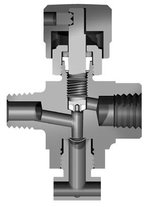
Orifice: 0.176" (4.5mm)
Model Shown: 4M4F-RV6ACK-18-SS
How to Order
Dimensions in inches/millimeters are for reference only, subject to change. Inline Pattern: 4M4F-RV6LCK-18-SS Angle Pattern: 4M4F-RV6ACK-18-SS
NOTES:
1) To obtain optional elastomeric stem packaging, insert one of the following designators prior to “-SS”: -BN Nitrile rubber -V Fluorocarbon rubber -EPR Ethylene propylene rubber -NE Neoprene rubber.
Example: 4M4F-RV6LCK-18-V-SS
2) To obtain the optional high temperature gasket, add the suffix -HT to the end of the part number.
Example: 4M4F-RV6LCK-18-V-SS-HT
6
48 Parker
http://www.parker.com/ipdus Catalog 4110-NV
& Accessories Cyl & Acc
Series Combination Rupture Disc / Needle
Features Combines the V4LC Series valve and the RV Series rupture disc unit into a small package Stainless steel construction Tapered bore PTFE packing K stem (PCTFE stem tip) Knurled aluminum handle Inline and angle patterns Optional stem packings
Hannifin Corporation Instrumentation Products Division Jacksonville, AL USA
Cylinders
RV6C
Valves
Model Shown: 4M4F-RV6LCK-18-SS () Denotes dimensions in millimeters
Materials of Construction Item # Description Material 1 Stem ASTM A 276 Type 316 with PCTFE 2 Packing Nut ASTM A 479 Type 316 3 Body ASTM A 182 Type F316 4 Plug ASTM A 479 Type 316 5 Handle Set Screw 316 Stainless Steel 6 Handle ASTM B 211 Alloy A92024 7 Packing PTFE 8 Lower Packing Washer 316 Stainless Steel 9 Gasket PTFE or 316 Stainless Steel with PTFE coating 10 Rupture Disc AISI Type 316 11 Upper Packing Washer Commercial Brass
Perfluorinated polyether
Lubrication:
Specifications
bar)
Pressure Rating: Valve – 5000 psig CWP (345
Rupture Disc – 1800 psig (124 bar)
8 1 7 4 5 10 11 3
2 9
Catalog 4110-NV
Dip (Outage) Tube Valves and Fittings
Parker Sample Cylinder Valves and Rupture Disc Units may be fitted with customer specified dip tubes to prevent overfilling of cylinders by providing a vapor space in sample cylinders containing liquified gases. Parker Dip Tube Fittings permit the assembly of any valve with a dip tube.
How to Order Dip Tubes with Sample Cylinder Valves and Rupture Disc Units
A 316 stainless steel dip tube will be supplied press fit to the Male NPT port of products when specified by adding the dip tube length to the end of the part number. The length is measured from the end of the forging.
Example 1: 4M4F-RV6L-18-SS-4. Describes a Rupture Disc Unit with a four inch (102mm) long dip tube.
Example 2: 4M4F-RV6LCK-18-SS-2. Describes a Combination Rupture Disc / Needle Valve with a two inch (51 mm) long dip tube.
How to Order Dip Tube Fittings
Dimensions in inches/millimeters are for reference only, subject to change.
A 316 stainless steel dip tube will be supplied press fit to the Male NPT port of Male x Female Pipe Adapters. They are available with 1/4" or 1/2" NPT threads. Specify the custom DT6L fitting by adding the dip tube length to the end of the part number. The length is measured from the end of the forging.
Example 1: 4M4F-DT6L-SS-3. Describes a 1/4" MNPT x 1/4" FNPT Fitting with a 3 inch (76 mm) long dip tube.
Example 2: 8M8F-DT6L-SS-2. Describes a 1/2" MNPT x 1/2" FNPT Fitting with a 2 inch (51 mm) long dip tube.
Note: For further information on Dip (Outage) Tubes, refer to Parker Engineering Performance Report EPR4160.2
Other Valves for use with Sample Cylinders
V Series Needle Valves
SN Series Needle Valves
&
Model Shown: 4M4F-RV6L-SS-2
Model Shown: 4M4F-DT6L-SS-2
Parker Hannifin
Instrumentation
Jacksonville, AL USA http://www.parker.com/ipdus
49
Corporation
Products Division
Cylinders
Accessories Cyl & Acc
End Conn
End Connections
Available End Connections
Standard End Connections
A – Two ferrule A-LOK® compression port
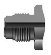
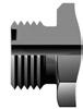
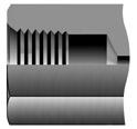
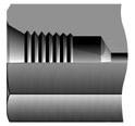
Z – Single ferrule CPI™ compression port
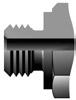
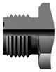
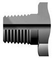
F – ANSI/ASME B1.20.1 internal pipe threads
M – ANSI/ASME B1.20.1 external pipe threads
V – VacuSeal face seal port Q – UltraSeal face seal port
MP7 – Parker MPI™ (Medium Pressure Inverted)
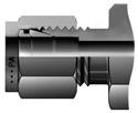
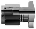
Non-Standard End Connections
TA – Tube adapter connection
F5 – SAE J1926/2, Part 2: Heavy-duty (S Series) stud ends
G5 – SAE J1926/1, Part 1: Threaded port with O-ring seal in truncated housing
L – SAE J1453, Fitting – O-ring face seal – External thread with O-ring groove designed to seal with an elastomer against a sleeve
KF – British Standard BS 21 (ISO 7-1), Internal pipe threads
KM – British Standard BS 21 (ISO 7-1), External pipe threads
Parker Hannifin Corporation Instrumentation Products Division Jacksonville, AL USA http://www.parker.com/ipdus
50
Catalog 4110-NV
Catalog 4110-NV
Offer of Sale
Offer of Sale
The items described in this document and other documents and descriptions provided by Parker Hannifin Corporation, its subsidiaries and its authorized distributors (“Seller”) are hereby offered for sale at prices to be established by Seller. This offer and its acceptance by any customer (“Buyer”) shall be governed by all of the following Terms and Conditions. Buyer’s order for any item described in its document, when communicated to Seller verbally, or in writing, shall constitute acceptance of this offer. All goods or work described will be referred to as “Products”.
1. Terms and Conditions. Seller’s willingness to offer Products, or accept an order for Products, to or from Buyer is expressly conditioned on Buyer’s assent to these Terms and Conditions and to the terms and conditions found on-line at www.parker.com/saleterms/. Seller objects to any contrary or additional term or condition of Buyer’s order or any other document issued by Buyer.
2. Price Adjustments; Payments. Prices stated on the reverse side or preceding pages of this document are valid for 30 days. After 30 days, Seller may change prices to reflect any increase in its costs resulting from state, federal or local legislation, price increases from its suppliers, or any change in the rate, charge, or classification of any carrier. The prices stated on the reverse or preceding pages of this document do not include any sales, use, or other taxes unless so stated specifically. Unless otherwise specified by Seller, all prices are F.O.B. Seller’s facility, and payment is due 30 days from the date of invoice. After 30 days, Buyer shall pay interest on any unpaid invoices at the rate of 1.5% per month or the maximum allowable rate under applicable law.
3. Delivery Dates; Title and Risk; Shipment. All delivery dates are approximate and Seller shall not be responsible for any damages resulting from any delay. Regardless of the manner of shipment, title to any products and risk of loss or damage shall pass to Buyer upon tender to the carrier at Seller’s facility (i.e., when it’s on the truck, it’s yours). Unless otherwise stated, Seller may exercise its judgment in choosing the carrier and means of delivery. No deferment of shipment at Buyers’ request beyond the respective dates indicated will be made except on terms that will indemnify, defend and hold Seller harmless against all loss and additional expense. Buyer shall be responsible for any additional shipping charges incurred by Seller due to Buyer’s changes in shipping, product specifications or in accordance with Section 13, herein.
4. Warranty. Seller warrants that the Products sold hereunder shall be free from defects in material or workmanship for a period of twelve months from the date of delivery to Buyer or 2,000 hours of normal use, whichever occurs first. This warranty is made only to Buyer and does not extend to anyone to whom Products are sold after purchased from Seller. The prices charged for Seller’s products are based upon the exclusive limited warranty stated above, and upon the following disclaimer: DISCLAIMER OF WARRANTY: THIS WARRANTY COMPRISES THE SOLE AND ENTIRE WARRANTY PERTAINING TO PRODUCTS PROVIDED HEREUNDER. SELLER DISCLAIMS ALL OTHER WARRANTIES, EXPRESS AND IMPLIED, INCLUDING MERCHANTABILITY AND FITNESS FOR A PARTICULAR PURPOSE.
5. Claims; Commencement of Actions. Buyer shall promptly inspect all Products upon delivery. No claims for shortages will be allowed unless reported to the Seller within 10 days of delivery. No other claims against Seller will
be allowed unless asserted in writing within 60 days after delivery or, in the case of an alleged breach of warranty, within 30 days after the date within the warranty period on which the defect is or should have been discovered by Buyer. Any action based upon breach of this agreement or upon any other claim arising out of this sale (other than an action by Seller for any amount due to Seller from Buyer) must be commenced within thirteen months from the date of tender of delivery by Seller or, for a cause of action based upon an alleged breach of warranty, within thirteen months from the date within the warranty period on which the defect is or should have been discovered by Buyer.
6. LIMITATION OF LIABILITY. UPON NOTIFICATION, SELLER WILL, AT ITS OPTION, REPAIR OR REPLACE A DEFECTIVE PRODUCT, OR REFUND THE PURCHASE PRICE. IN NO EVENT SHALL SELLER BE LIABLE TO BUYER FOR ANY SPECIAL, INDIRECT, INCIDENTAL OR CONSEQUENTIAL DAMAGES ARISING OUT OF, OR AS THE RESULT OF, THE SALE, DELIVERY, NON-DELIVERY, SERVICING, USE OR LOSS OF USE OF THE PRODUCTS OR ANY PART THEREOF, OR FOR ANY CHARGES OR EXPENSES OF ANY NATURE INCURRED WITHOUT SELLER’S WRITTEN CONSENT, EVEN IF SELLER HAS BEEN NEGLIGENT, WHETHER IN CONTRACT, TORT OR OTHER LEGAL THEORY. IN NO EVENT SHALL SELLER’S LIABILITY UNDER ANY CLAIM MADE BY BUYER EXCEED THE PURCHASE PRICE OF THE PRODUCTS.
7. Contingencies. Seller shall not be liable for any default or delay in performance if caused by circumstances beyond the reasonable control of Seller.
8. User Responsibility. The user, through its own analysis and testing, is solely responsible for making the final selection of the system and Product and assuring that all performance, endurance, maintenance, safety and warning requirements of the application are met. The user must analyze all aspects of the application and follow applicable industry standards and Product information. If Seller provides Product or system options, the user is responsible for determining that such data and specifications are suitable and sufficient for all applications and reasonably foreseeable uses of the Products or systems.
9. Loss to Buyer’s Property. Any designs, tools, patterns, materials, drawings, confidential information or equipment furnished by Buyer or any other items which become Buyer’s property, may be considered obsolete and may be destroyed by Seller after two consecutive years have elapsed without Buyer placing an order for the items which are manufactured using such property. Seller shall not be responsible for any loss or damage to such property while it is in Seller’s possession or control.
10. Special Tooling. A tooling charge may be imposed for any special tooling, including without limitation, dies, fixtures, molds and patterns, acquired to manufacture Products.
Parker Hannifin Corporation Instrumentation Products Division Jacksonville, AL USA http://www.parker.com/ipdus
51
Offer of Sale
Such special tooling shall be and remain Seller’s property notwithstanding payment of any charges by Buyer. In no event will Buyer acquire any interest in apparatus belonging to Seller which is utilized in the manufacture of the Products, even if such apparatus has been specially converted or adapted for such manufacture and notwithstanding any charges paid by Buyer. Unless otherwise agreed, Seller shall have the right to alter, discard or otherwise dispose of any special tooling or other property in its sole discretion at any time.
11. Buyer’s Obligation; Rights of Seller. To secure payment of all sums due or otherwise, Seller shall retain a security interest in the goods delivered and this agreement shall be deemed a Security Agreement under the Uniform Commercial Code. Buyer authorizes Seller as its attorney to execute and file on Buyer’s behalf all documents Seller deems necessary to perfect its security interest. Seller shall have a security interest in, and lien upon, any property of Buyer in Seller’s possession as security for the payment of any amounts owed to Seller by Buyer.
12. Improper use and Indemnity. Buyer shall indemnify, defend, and hold Seller harmless from any claim, liability, damages, lawsuits, and costs (including attorney fees), whether for personal injury, property damage, patent, trademark or copyright infringement or any other claim, brought by or incurred by Buyer, Buyer’s employees, or any other person, arising out of: (a) improper selection, improper application or other misuse of Products purchased by Buyer from Seller; (b) any act or omission, negligent or otherwise, of Buyer; (c) Seller’s use of patterns, plans, drawings, or specifications furnished by Buyer to manufacture Product; or (d) Buyer’s failure to comply with these terms and conditions. Seller shall not indemnify Buyer under any circumstance except as otherwise provided.
13. Cancellations and Changes. Orders shall not be subject to cancellation or change by Buyer for any reason, except with Seller’s written consent and upon terms that will indemnify, defend and hold Seller harmless against all direct, incidental and consequential loss or damage. Seller may change product features, specifications, designs and availability with notice to Buyer.
14. Limitation on Assignment. Buyer may not assign its rights or obligations under this agreement without the prior written consent of Seller.
15. Entire Agreement. This agreement contains the entire agreement between the Buyer and Seller and constitutes the final, complete and exclusive expression of the terms of the agreement. All prior or contemporaneous written or oral agreements or negotiations with respect to the subject matter are herein merged.
16. Waiver and Severability. Failure to enforce any provision of this agreement will not waive that provision nor will any such failure prejudice Seller’s right to enforce that provision in the future. Invalidation of any provision of this agreement by legislation or other rule of law shall not invalidate any other provision herein. The remaining provisions of this agreement will remain in full force and effect.
17. Termination. This agreement may be terminated by Seller for any reason and at any time by giving Buyer thirty (30) days written notice of termination. In addition, Seller may
by written notice immediately terminate this agreement for the following: (a) Buyer commits a breach of any provision of this agreement (b) the appointment of a trustee, receiver or custodian for all or any part of Buyer’s property (c) the filing of a petition for relief in bankruptcy of the other Party on its own behalf, or by a third party (d) an assignment for the benefit of creditors, or (e) the dissolution or liquidation of the Buyer.
18. Governing Law. This agreement and the sale and delivery of all Products hereunder shall be deemed to have taken place in and shall be governed and construed in accordance with the laws of the State of Ohio, as applicable to contracts executed and wholly performed therein and without regard to conflicts of laws principles. Buyer irrevocably agrees and consents to the exclusive jurisdiction and venue of the courts of Cuyahoga County, Ohio with respect to any dispute, controversy or claim arising out of or relating to this agreement. Disputes between the parties shall not be settled by arbitration unless, after a dispute has arisen, both parties expressly agree in writing to arbitrate the dispute.
19. Indemnity for Infringement of Intellectual Property Rights. Seller shall have no liability for infringement of any patents, trademarks, copyrights, trade dress, trade secrets or similar rights except as provided in this Section. Seller will defend and indemnify Buyer against allegations of infringement of U.S. patents, U.S. trademarks, copyrights, trade dress and trade secrets (“Intellectual Property Rights”). Seller will defend at its expense and will pay the cost of any settlement or damages awarded in an action brought against Buyer based on an allegation that a Product sold pursuant to this Agreement infringes the Intellectual Property Rights of a third party. Seller’s obligation to defend and indemnify Buyer is contingent on Buyer notifying Seller within ten (10) days after Buyer becomes aware of such allegations of infringement, and Seller having sole control over the defense of any allegations or actions including all negotiations for settlement or compromise. If a Product is subject to a claim that it infringes the Intellectual Property Rights of a third party, Seller may, at its sole expense and option, procure for Buyer the right to continue using the Product, replace or modify the Product so as to make it noninfringing, or offer to accept return of the Product and return the purchase price less a reasonable allowance for depreciation. Notwithstanding the foregoing, Seller shall have no liability for claims of infringement based on information provided by Buyer, or directed to Products delivered hereunder for which the designs are specified in whole or part by Buyer, or infringements resulting from the modification, combination or use in a system of any Product sold hereunder. The foregoing provisions of this Section shall constitute Seller’s sole and exclusive liability and Buyer’s sole and exclusive remedy for infringement of Intellectual Property Rights.
20. Taxes. Unless otherwise indicated, all prices and charges are exclusive of excise, sales, use, property, occupational or like taxes which may be imposed by any taxing authority upon the manufacture, sale or delivery of Products.
21. Equal Opportunity Clause. For the performance of government contracts and where dollar value of the Products exceed $10,000, the equal employment opportunity clauses in Executive Order 11246, VEVRAA, and 41 C.F.R. §§ 601.4(a), 60-741.5(a), and 60-250.4, are hereby incorporated.
Parker Hannifin Corporation Instrumentation Products Division Jacksonville, AL USA http://www.parker.com/ipdus
52
Catalog 4110-NV
01/09
Parker’s Motion & Control Technologies
At Parker, we’re guided by a relentless drive to help our customers become more productive and achieve higher levels of profitability by engineering the best systems for their requirements. It means looking at customer applications from many angles to find new ways to create value. Whatever the motion and control technology need, Parker has the experience, breadth of product and global reach to consistently deliver. No company knows more about motion and control technology than Parker. For further info call 1-800-C-Parker.
AEROSPACE
Key Markets
Aircraft engines

Business & general aviation
Commercial transports

Land-based weapons systems
Military aircraft Missiles & launch vehicles
Regional transports Unmanned aerial vehicles
Key Products
Flight control systems & components

Fluid conveyance systems

Fluid metering delivery & atomization devices
Fuel systems & components

Hydraulic systems & components
Inert nitrogen generating systems
Pneumatic systems & components Wheels & brakes
CLIMATE CONTROL
Key Markets
Agriculture
Air conditioning
Food, beverage & dairy

Precision cooling Processing
Transportation
Key Products
CO2 controls
Electronic controllers
Filter driers
Hand shut-off valves
Hose & fittings
Pressure regulating valves
Refrigerant distributors
Safety relief valves
Solenoid valves
Thermostatic expansion valves
ELECTROMECHANICAL
Key Markets
Aerospace
Factory automation
Life science & medical
Machine tools

Packaging machinery
Paper machinery
Plastics machinery & converting
Primary metals
Semiconductor & electronics Textile Wire & cable
Key Products
AC/DC drives & systems
Electric actuators, gantry robots & slides
Electrohydrostatic actuation systems
Electromechanical actuation systems
Human machine interface
Linear motors
Stepper motors, servo motors, drives & controls
Structural extrusions
FILTRATION
Key Markets
Food & beverage
Industrial machinery
Life sciences
Marine
Mobile equipment Oil & gas

Power generation Process Transportation
Key Products
Analytical gas generators
Compressed air & gas filters
Condition monitoring
Engine air, fuel & oil filtration & systems
Hydraulic, lubrication & coolant filters
Process, chemical, water & microfiltration filters
Nitrogen, hydrogen & zero air generators
FLUID
HANDLING
PNEUMATICS
Markets Aerospace Conveyor & material handling Factory automation Life science & medical Machine tools Packaging machinery Transportation & automotive
Products Air preparation Brass fittings & valves Manifolds Pneumatic accessories Pneumatic actuators & grippers Pneumatic valves & controls Quick disconnects Rotary actuators Rubber & thermoplastic hose & couplings
extrusions
tubing & fittings Vacuum generators, cups & sensors
Key
Key
Structural
Thermoplastic
&
Markets Aerospace Agriculture Bulk chemical handling Construction machinery Food & beverage Fuel & gas delivery Industrial machinery Mobile Oil & gas Transportation Welding Key Products Brass fittings & valves Diagnostic equipment Fluid conveyance systems Industrial hose PTFE & PFA hose, tubing & plastic fittings Rubber & thermoplastic hose & couplings Tube fittings & adapters Quick disconnects
Key Markets Aerospace Aerial lift Agriculture Construction machinery Forestry Industrial machinery Mining Oil & gas Power generation & energy Truck hydraulics Key Products Diagnostic equipment Hydraulic cylinders & accumulators Hydraulic motors & pumps Hydraulic systems Hydraulic valves & controls Power take-offs Rubber & thermoplastic hose & couplings Tube fittings & adapters Quick disconnects PROCESS CONTROL Key Markets Chemical & refining Food, beverage & dairy Medical & dental Microelectronics Oil & gas Power generation Key Products Analytical sample conditioning products & systems Fluoropolymer chemical delivery fittings, valves & pumps High purity gas delivery fittings, valves & regulators Instrumentation fittings, valves & regulators Medium pressure fittings & valves Process control manifolds
Key Markets Aerospace Chemical processing Consumer Energy, oil & gas Fluid power General industrial Information technology Life sciences Military Semiconductor Telecommunications Transportation
Products Dynamic seals Elastomeric o-rings EMI shielding Extruded & precision-cut, fabricated elastomeric seals
& inserted elastomeric shapes
temperature metal seals Metal & plastic retained composite seals Thermal management
GAS
Key
HYDRAULICS
SEALING & SHIELDING
Key
Homogeneous
High
Sales Offces Worldwide
Parker Hannifin Corporation
Instrumentation Products Division 1005 A Cleaner Way Huntsville, AL 35805 USA phone 256 881 2040 fax 256 881 5072 www.parker.com/ipdus
Parker Hannifin Corporation
Instrumentation Products Division 2651 Alabama Highway 21 North Jacksonville, AL 36265-9681 USA phone 256 435 2130 fax 256 435 7718 www.parker.com/ipdus
Parker Hannifin Corporation
Instrumentation Products Division 6575 Tram Road Beaumont, TX 77713 USA phone 409 924 0300 fax 409 924 0301 www.parker.com/ipdus
Parker Hannifin plc
Instrumentation Products Division Riverside Road Pottington Business Park Barnstaple, Devon EX31 1NP England phone +44 0 1271 313131 fax +44 0 1271 373636 email ipd@parker.com www.parker.com/ipd
Parker Hannifn Corporation
Instrumentation Products Division 2651 Alabama Highway 21 North Jacksonville, AL 36265-9681 phone 256 435 2130 fax 256 435 7718 www.parker.com/ipdus
Your Local Authorized Parker Distributor
Catalog 4110-NV December 2010 DP

