500 and 600 Series
Gas Mass Flow Instruments
Digital Electronics Give High Accuracy with Enhanced Performance
Porter Series 500 Mass Flow Meters (MFMs) and Series 600 Mass Flow Controllers (MFCs) accurately measure and control flow rates of a wide variety of gases from 5 standard cubic centimeters per minute (SCCM) to 1000 standard liters per minute (SLPM) full scale nitrogen flow for operating pressures up to 1500 PSIG.
Series 500 MFMs and Series 600 MFCs feature performance-enhancing digital electronics, improved accuracy and repeatability, multi-gas capability and self-diagnostics. Both Series 500 and Series 600 are available with traditional analog inputs and outputs, an RS232 connection and Modbus, Profibus or DeviceNet digital protocol.
Contact Information:
Parker Hannifin Corporation
Porter Instrument Division
245 Township Line Road
Hatfield, PA 19440
Phone 215 723 4000
Fax 215 723 2199
industrial@parker.com
www.parker.com/porter
Product Features:
• Digital Electronics
• Percentage of Reading Accuracy & Repeatability
• Multi-Gas Capability
• Analog I/O, RS232, Modbus, Profibus DP or DeviceNet Protocol
• Self-Diagnostics
• LED Operation Indicators
• Operating Pressures to 3000 PSIG
• Alarm and Counter Functions
• Remotely Adjustable Control Settings
• Single Power Supply Operation
Specifications
Performance
Flow Capacities*
Any flow range from 0-5 SCCM to 0-1000 SLPM (nitrogen equivalent)
*Note: The flow ranges listed are the minimum and maximum nitrogen (N2) flow ranges available. Intermediate flow ranges are available. For correct sizing when operating parameters are questionable, please consult the factory.
Response Time (per SEMI E17-91
Settling Time)
Accuracy & Linearity
Repeatability
1 to 2 seconds (consult factory for applications requiring faster response times)
±1.0% of reading (20%-100% full scale)
±0.8% of reading plus ±0.2% full scale (below 20% full scale)
Within ±0.2% of reading at any constant temperature within operating temperature range
Rangeability (Control Range) 50:1 (2%-100% full scale) (accuracy and control)
Ambient and Operating Temperature Range -10°C to 70ºC (+14°F to 158ºF)
1500 PSIG – Models 511 & 512
Setpoint Input/Flow Signal
Maximum Operating Pressures
Temperature Coefficient (per SEMI E18-91 Zero Effect and Span Effect)
Pressure Coefficient (per SEMI E28-92 Total Calibration Effect)
1000 PSIG – Models 513 514, 601, 602 & 651
200 PSIG – Models 602A, 603A & 604A
±0.05% full scale/ºC of zero
±0.05% of reading/ºC of span
± 0.1%/atmosphere typical using nitrogen (N2)
Mounting Orientation Attitude insensitive
Warm-up Time 10 minutes
Nine (9)-pin D-connector (all units)
RJ-45 connector (Modbus only)
0-100% (Modbus, Profibus DP, DeviceNet) 0-100% (Modbus, Profibus DP, DeviceNet)
External Electrical Connector
Nine (9)-pin D-connector (Profibus only)
TURK B 8151-0-PG 9 (DeviceNet only)
(MFCs only)
Stainless Steel, 316 Stainless Steel, 430F Stainless Steel and Sandvik® 1802
Elastomers Buna N, EPDM, Kalrez® , Neoprene or Viton®
Sandvik® is a registered trademark of AB Sandvik Materials Technology. Kalrez® and Viton® are registered trademarks of DuPont Dow Elastomers L.L.C.
Ordering Information
To order, please specify:
n Model number
n Type of output signal
n Elastomer material
Power Supply Requirements
(Current Consumption <250 mAdc)
All models operate from nominal power supply voltages of +15 or +24
Specifications subject to change.
n Process connection size and type
n Flow capacity
n Gas type
n Operating temperature
n Inlet (supply) pressure
n Outlet pressure (not required for MFMs)
n Calibration standard (i.e. 0°C, 20°C, 21.1°C or 25°C)
n Additional accessories required
Vdc
Output: Setpoint Flow Signal 0-5 Vdc 0-5 Vdc
minimum load resistance) 0-10 Vdc 0-10 Vdc
minimum load resistance) 4-20 mAdc 4-20 mAdc
(refer
Load
Values
output 200-750
Vdc
Body 316 Stainless Steel Sensor Assembly 316L
Orifice
316
Valve
(2K ohm
(3K ohm
(sourcing)
to load resistance values below)
Resistance
for 4-20 mAdc flow signal
ohm for 15-30
loop supply voltage Materials
Stainless Steel
(MFCs only)
Stainless Steel
Components (Wetted)
302
Process
Connections 316 Stainless Steel
Ordering Information
Model Number and Description
Example: 601- A
Model Model Number
Model Revision Level
Factory Assigned
Response Time
A 1 to 2 seconds (standard)
B 500 msec (optional)
PCB Setpoint & Outage Signal (Power Supply Voltage)
A 0-5 Vdc (+15 Vdc)
B 0-5 Vdc (+24 Vdc)
C DeviceNet (+15Vdc)
D DeviceNet (+24 Vdc)
E 0-10 Vdc (+15 Vdc)
F 0-10 Vdc (+24 Vdc)
G 4-20 mAdc (sourcing) (+15 Vdc)
H 4-20 mAdc (sourcing) (+24 Vdc)
L Modbus (+15 Vdc)
M Modbus (+24 Vdc)
P Profibus DP (+24 Vdc)
R Profibus DP (+15 Vdc)
Body Material
S 316 Stainless Steel
Assembly/Calibration Features
AA Factory Standard
Process Connection Size and Type
A 3/8" CPI™
B 1/8" Compression
C 1/4" Compression
D 3/8" Compression
E 1/2" Compression
F 1/2" CPI™
G 3/4" Compression
H 10mm Compression
I 1/4" CPI™
J 1/4" MORFS(1)
K 3/8" MORFS(1)
L 1/2" MORFS(1)
P 1/4" MMGFS(2)
Q 3/8" MMGFS(2
S 1/2" MMGFS(2)
U 3/8" A-LOK®
V 1/2" A-LOK®
W 6mm Compression
X No Connections
Y 1/4" A-LOK®
Z Special Connections
1 8mm A-LOK®
2 3/4" A-LOK®
3 12 mm Compression
6 1/8" A-LOK®
7 1/8" CPI™
8 1/4" VacuSeal™
9 1/2" VacuSeal™
(1) MORFS = Male O-Ring Face Seal
(2) MMGFS = Male Metal Gasket Face Seal
Elastomers (Valve Seat / O-Rings)
B Buna N / Buna N
E EPDM / EPDM
K Kalrez® / Kalrez®
N Neoprene / Neoprene
V Viton® / Viton®
For model number options not shown above, please consult factory.
Available Models
Note: The flow ranges listed are the minimum and maximum nitrogen (N2) flow ranges available for each given model. Intermediate flow ranges are available. For correct sizing when operating parameters are questionable, please consult the factory.
Mass Flow Meters:
Model 5110-5 SCCM to 0-10 SLPM N2
Model 5120-10 SLPM to 0-100 SLPM N2
Model 5130-100 SLPM to 0-500 SLPM N2
Model 5140-500 SLPM to 0-1000 SLPM N2
Mass Flow Controllers:
Model 6010-5 SCCM to 0-10 SLPM N2
Model 6510-10 SLPM to 0-50 SLPM N2
Model 6020-10 SLPM to 0-100 SLPM N2
Model 602A 0-10 SLPM to 0-100 SLPM N2 (low DP)
Model 603A0-100 SLPM to 0-500 SLPM N2
Model 604A0-500 SLPM to 0-1000 SLPM N2
M S V
A
Y AA
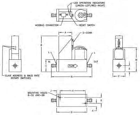
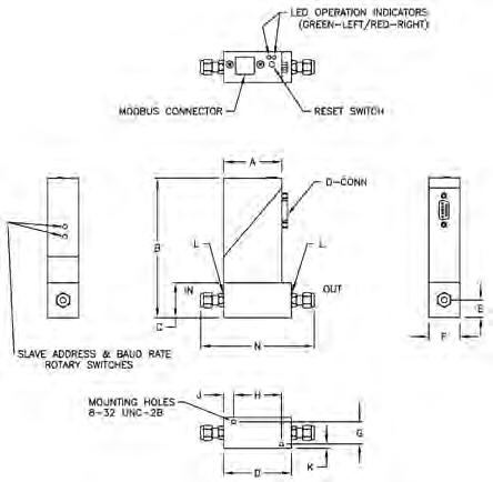
Dimensions (Dimensions shown in inches)
Series 600 Mass Flow Controller Series 500 Mass Flow Meter
For process connection options not shown, please consult factory.
WARNING – USER RESPONSIBILITY
FAILURE OR IMPROPER SELECTION OR IMPROPER USE OF THE PRODUCTS DESCRIBED HEREIN OR RELATED ITEMS CAN CAUSE DEATH, PERSONAL INJURY AND PROPERTY DAMAGE.
This document and other information from Parker-Hannifin Corporation, its subsidiaries and authorized distributors provide product or system options for further investigation by users having technical expertise.
The user, through its own analysis and testing, is solely responsible for making the final selection of the system and components and assuring that all performance, endurance, maintenance, safety and warning requirements of the application are met. The user must analyze all aspects of the application, follow applicable industry standards, and follow the information concerning the product in the current product catalog and in any other materials provided from Parker or its subsidiaries or authorized distributors.
To the extent that Parker or its subsidiaries or authorized distributors provide component or system options based upon data or specifications provided by the user, the user is responsible for determining that such data and specifications are suitable and sufficient for all applications and reasonably foreseeable uses of the components or systems.
Offer of Sale
The items described in this document are hereby offered for sale by Parker-Hannifin Corporation, its subsidiaries or its authorized distributors. This offer and its acceptance are governed by the provisions stated in the detailed “Offer of Sale” elsewhere in this document or available at www.parker.com/offerofsale.
Bulletin FM-1118 Rev E Apr 2012
© 2012 Parker Hannifin Corporation
Dimension “N” Model511512513514601602602A603A604A651 A-LOK® CPI™ 1/8"4.027 N/A 4.845 N/A 1/4"4.2074.584N/A5.0256.3557.261N/A5.025 3/8"4.3274.7045.939N/A5.1456.4757.3818.499N/A5.145 1/2"4.4874.8646.1597.5945.3056.6357.5418.7198.7195.305 3/4"N/A6.4797.914N/A7.9819.0399.0395.745 VacuSeal™ 1/4"4.0674.444N/A4.8856.2157.121N/A4.885 3/8"4.3674.7446.1797.6145.1856.5157.4218.7398.7395.185 1/2"4.3674.7446.1797.6145.1856.5157.4218.7398.7395.185 N/A = Not Available Series 500 Dimensions Model511512513514 A 1.8301.8301.8301.830 B 4.5205.1455.8955.895 C 1.1251.7502.5002.500 D 2.1872.5643.7395.174 E 0.5000.8751.2501.250 F 1.0001.7502.5002.500 G 0.7200.8281.3181.318 H 1.5401.8622.9532.953 J 0.3240.5110.5901.307 K 0.1400.4610.5910.591 L 9/16-189/16-183/4-163/4-16 N Refer to Dimension “N” table at right Series 600 Dimensions Model601602602A603A604A651 A 1.8301.8301.8301.8301.8301.830 B 4.5205.1455.2705.8955.8954.895 C 1.1251.7501.8752.5002.5001.500 D 3.0054.3355.2416.2996.2993.005 E 0.5000.8750.8751.2501.2500.750 F 1.0001.7501.8752.5002.5001.000 G 0.7200.8280.8281.3181.3180.720 Model601602602A603A604A651 H
J
K 0.1400.4610.5230.5910.5910.140 L 9-16/189-16/189-16/183/4-163/4-169-16/18 M 2.2183.5693.7704.3954.3953.066 N
to
“N” table below
2.7203.6344.5395.5125.5121.897
0.1450.5110.5110.5900.5900.963
Refer
Dimension
