P810
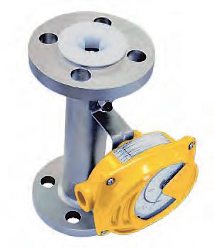
The P810 Series Metal Tube PFA lined Variable Area flow meter is a simple yet highly accurate flow meter conforming to the latest industry standards.
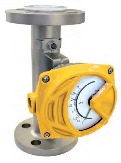

The meter comes with a PFA lined tube which is capable of measuring corrosive fluids and aggressive fluid media. Additionally, it has excellent chemical resistance, impermeability and stress crack resistance.
The industry standard 250 mm face-to-face dimension on the P810 simplifies piping design, resulting in engineering and installation space savings as well as retrofit capability for other manufacturers.
Product Features: • Standardized face-to-face dimensions for all sizes from 3/4" to 4", enables system design efficiencies • Reinforced lining to suppress buckling, exfoliation and deformation of PFA layer
Series Lined Tube Variable Area Flow Meter Contact Information: Parker Hannifin Corporation Porter Instrument Division 245 Township Line Road Hatfield, PA 19440
215 723 4000 Fax 215 723 2199 industrial@parker.com www.porterinstrument.com
chemical resistance, impermeability and stress crack resistance
can be produced in any volume unit or mass flow units.
options include alarm contacts
Phone
• Excellent
• Scales
• Other
Flow Rate Scale Ranges Liquid1 Minimum Maximum
0.6 - 5.2 Gal/min (150 - 1200 L/hr) 88 - 220 Gal/min (19980 - 49980 L/hr) Gas2 Minimum Maximum For all gas applications, consult factory Turndown 10:1 Accuracy ±2.0% F.S. Approx. Weight 5.5 - 40 lbs. (2.5 - 18 kg) Indicator Construction IP 65 equivalent to NEMA 12/13 (JIS C920) Alarm Type 1 Point Reed Switch Alarm
Operating Conditions Max. Operating Pressure • At ambient temperature • At 248°F (120°C) 479 psig (33 barg) 479 psig (33 barg)
Oper. Fluid Temp. Range Local Indication Model -14°F - +248°F (-10°C - +120°C)
Oper. Ambient Temp. Range Local Indication Model -13°F - +212°F (-25°C - +100°C)
Connection Size Table
Availability of Connection Size Against Meter Size Meter Size Connection Rating 1 Size Smaller than Meter
Same Size as Meter
1 Size Larger than Meter (inch)(mm)
10K No YesYes 20K No YesYes 150LbNo YesYes 300LbNo YesYes 2 50 Flow Capacities
10K No YesYes 20K No YesYes 150LbNo YesYes 300LbNo YesYes 3 80 Viscosity Table Meter
10K No YesYes 20K No YesYes 150LbNo YesYes 300LbNo Yes No
Water1 Flow Rate Table Meter Size Water Max. Pressure Drop (Water) (in)(mm)(Gal/min)(L/h)(psi)(bar) 3/4 200.6 - 5.2150 - 12001.010.07 1 25 3 - 15.4700 - 35001.450.1 1-1/2 4013.2 - 26.43000 - 60000.725.05 2 50 22 - 665000 - 150001.3.09 3 80 44 - 11010000 - 250001.450.1 4 100 88 - 22020000 - 500001.160.08 1 Water density 1.0g/cm3, viscosity 1.0cP.
10K No YesYes 20K No YesYes 150LbNo YesYes 300LbNo Yes No 4 100 Accuracy cPMeasurement cP
Size Upper-limit Viscosity for: Assured
20mm 10 30 25mm 15 150 40mm 15 150 50mm 50 200 80mm 50 200 100mm 50 200
Specifications
Die Cast
Materials of Construction Wetted Flange 316 Stainless Steel Tapered Tube PFA Float Guide PFA Float PFA or PTFE/PFA Housing Support 316 Stainless Steel Non-wetted Indicator 12 Aluminum
Performance
equivalent
water density
2Gases equivalent to Air @ 0°C 1 atm
1Liquid
to
1.0g/cm3, viscosity 1.0cp
1/215
10K No YesYes 20K No YesYes 150LbNo YesYes 300LbNo YesYes 1 25
10K No YesYes 20K No YesYes 150LbNo YesYes 300LbNo YesYes 1-1/240
DN20, (3/4"), PFA
DN25, (1"), PFA
DN40, (1-1/2"), PFA
DN50, (2"), PFA
DN65, (2-1/2"), PFA
DN80, (3"), PFA
DN100, (4"), PFA
Fluid Name: Operating Density or Specific Gravity: Viscosity: Flow Rate
Reed Switch – One contact closes (becomes ON) when value is more than set point
Reed Switch – One contact opens (becomes OFF) when value is more than set point
Reed Switch – One contact closes (becomes ON) when value is less than set point
Reed Switch – One contact opens (becomes OFF) when value is less than set point
Maximum: Operating Or Normal: Scale Range: Pressure Maximum: Operating or Normal: Temperature Maximum: Operating or Normal: Alarm Settings Alarm 1: Alarm 2: Other Options
Application Information
Ordering Information Model: P81 Connection Size/Wetted Material 1
2
3
4
5
6
7
Z
Connection Rating/Type A
RF B
Z
Internal Meter Size 1
2
3
4
5
6
Z Special Dampener A No
for liquid applications) D Dampener
gas
Indicator Type & Alarm Output/ Transmitter Functions A
B
Special
ANSI Class 150,
ANSI Class 300, RF
Special
15 MM
25 MM
40 MM
50 MM
80 MM
100 MM
dampener (typical
required (typical for
applications)
Liquid Indicator (standard)
C
D
E
Z Special Conduit Cable Entry ANone B
(F) CM20 X
(F) Z Special Intrinsically Safe & Explosion Proof Construction and Certification ANone Z Special Cleaning and Inspection A None Z Special Accessories 1None 3 Tags Z Special Example: P811A1AAA1A1 Liquid equivalent to water density 1.0g/cm3 , viscosity 1.0cP
NPT 1/2"
1.5
Dimensional Drawing
Parts/Materials
No. Parts Material 1 Flange SUS316
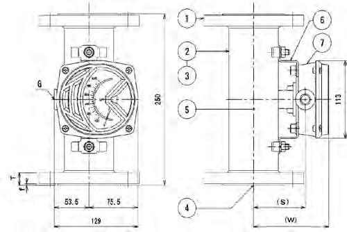
Body SUS316
Lining of Main Body PFA 4 Float Guide PFA 5 Float PFA or PTFE/PFA 6 Housing Support SUS316 7 Indicator ADC12
Proper material to be selected according to the specification.
Size
Meter Size (mm)
Dimensions (mm) and (in) Approx. Mass1 (kg) and (lb) LW 1515 (1/2)250 (9.84)115.5 (4.55)2.5 (5.5) 25 25 (1)250 (9.84)115.5 (4.55)4.0 (8.8) 4040 (1-1/2)250 (9.84)115.5 (4.55)4.5 (9.9) 5050 (2)250 (9.84)115.5 (4.55)7.0 (15.4) 8080 (3)250 (9.84)115.5 (4.55)13.0 (28.7) 100100 (4)250 (9.84)135.5 (5.33)18.0 (39.7)
Connection Size JIS A Size (inch)
1Approximate weights are shown for a meter with ANSI 150# flange
WARNING – USER RESPONSIBILITY
FAILURE OR IMPROPER SELECTION OR IMPROPER USE OF THE PRODUCTS DESCRIBED HEREIN OR RELATED ITEMS CAN CAUSE DEATH, PERSONAL INJURY AND PROPERTY DAMAGE.
This document and other information from Parker-Hannifin Corporation, its subsidiaries and authorized distributors provide product or system options for further investigation by users having technical expertise.
The user, through its own analysis and testing, is solely responsible for making the final selection of the system and components and assuring that all performance, endurance, maintenance, safety and warning requirements of the application are met. The user must analyze all aspects of the application, follow applicable industry standards, and follow the information concerning the product in the current product catalog and in any other materials provided from Parker or its subsidiaries or authorized distributors. To the extent that Parker or its subsidiaries or authorized distributors provide component or system options based upon data or specifications provided by the user, the user is responsible for determining that such data and specifications are suitable and sufficient for all applications and reasonably foreseeable uses of the components or systems.
Offer of Sale
The items described in this document are hereby offered for sale by Parker-Hannifin Corporation, its subsidiaries or its authorized distributors. This offer and its acceptance are governed by the provisions stated in the detailed “Offer of Sale” elsewhere in this document or available at www.parker.com/offerofsale.
Bulletin FM-1203 Rev A 2/2012 © 2012 Parker Hannifin Corporation
2
3
Accessories
Type
Switch
Voltage
Current Capacity
to 0.5
Switching Capacity
or 10 W
Contact
1 point Reed
Maximum
125 VAC or 100 VDC Operating
10 μA
A Maximum
10 VA
Suitable Wiring 0.2 to 2.5 mm2 / 24 to 12 AWG (single wire or stranded wire) Insulation Resistance 100 MΩ or more (500 V DC) Withstand Voltage 1500 V AC (holding time 1 min)
