Performance
Flow Rate Scale Ranges
Water1
Minimum
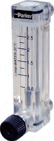
Small flow rate type 0.16 - 16 Gal/h (10 - 100 ml/min)
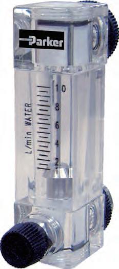
Large flow rate type 4.8 - 48 Gal/h (0.3 - 3 L/min)
Maximum
Air2 or N2
Minimum
Small flow rate type 4.8 - 48 Gal/h (0.3 - 3 L/min)
Large flow rate type 16 - 160 Gal/h (1 - 10 L/min)
Small flow rate type 0.4 - 4.2 ft3/h (nor) (0.2 - 20 L/min) (nor)
Large flow rate type 11 - 106 ft3/h (nor) (5 - 50 L/min) (nor)
Maximum
Small flow rate type 11 - 106 ft3/h (nor) (5 - 50 L/min) (nor)
Large flow rate type 64 - 636 ft3/h (nor) (30 - 300 L/min) (nor)
Turndown 10:1
Accuracy ±5% F.S.
Approx. Weight
Small flow rate type: 0.2 lbs. (95 g)
Large flow rate type: 0.27 lbs. (120 g)
Flow Direction Bottom rear to top rear
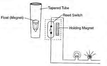
Alarm Type Reed Switch alarm
Operating Conditions
Max. Operating Pressure 72.5 psig (5 barg) Max. Operating Temperature 122°F (50°C) 1 Liquid equivalent to water density 1.0g/cm3, viscosity 1.0cp 2 Gases equivalent to Air @ 0°C 1 atm
Standard: Small flow rate NPT or RC 1/4" Large flow rate NPT or RC 3/8" with locknuts for front panel mounting Proper material to be selected according to the specification.
Reed Switch Specification
Contact
Reed switch (self-holding type)
Max. contact capacity: AC10VA, DC10W Max. voltage: AC125V, DC100V Max. current: 0.5A
Connection Lead wire connection of 50cm (2m is also available)
Reset-Span 25% Full Scale
Ambient Temperature -10°C to 60°C
Caution must be taken when mounting multiple alarmed meters. Close proximity may cause interference with alarm signal.
Materials of Construction Wetted Body Polymethyl Methacrylate (PMMA) Float 304 Stainless Steel, Glass, PTFE or Ruby Packing NBR (Nitrile Rubber) Fitting 304 Stainless Steel Valve 304 Stainless Steel Non-wetted Cover Polyoxymethylene Plastic (POM) Connection Size and Type
Number of Point 1 point (high or low) 2 point alarm also available as an option Consult factory for details Alarm Setting Range Standard 20% to 80% of full scale (H: 50% to 80%, L: 20% to 50%)
Panel
2 – ø 0.6 in (15 mm) 0.6 in (14 mm)
2 – ø 0.2 in (4 mm)
2 – NPT 1/8”
2 – ø 0.2 in (4 mm)
2 – M3 Depth 6 2 – NPT 1/8”
mm) 0.9 in (22 mm)
Panel PANEL CUT
Panel
OUT IN
2 – D
2 – NPT 3/8”
OUT IN
0.6 in (15 mm) 1.3 in (33 mm)
Small Air1 Flow Rate Table Flow Range Code
2 – ø 1 in (25 mm)
PANEL CUT
Large Air1 Flow Rate Table
0.4 in (9.5 mm) (0.04 in (1 mm))
103 (1) 22
2 – M3 Depth 6
(1.2 in (31 mm)) 1 in (25 mm)
2 – ø 0.6 in (15 mm) ø 0.5 in (12 mm)
0.08 in (2 mm) 0.5 in (12 mm) 0.5 in (12 mm)
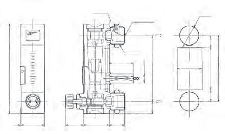
4.1 in (103 mm) 3.3 in (84 mm) 3.3 in (84 mm) 2.5 in (63 mm) 2.2 in (57 mm) 0.9 in (22 mm) Max 1.1 in (27 mm)
0.6 in (14 mm) 0.5 in (12 mm)
0.5 in (13.5 mm) 0.4 in (10.5 mm) 0.4 in (9.5 mm)
PANEL CUT
If No Alarm OutputIf LO, LC, HO, or HC Alarm Output Air or N2 Air or N2 Alarm Setting Range ft3/h L/min (nor) ft3/h L/min (nor) ft3/h L/min (nor) A 0.4 - 4.20.2 - 2N/A N/AN/AN/A B 1.1 - 110.5 - 5N/A N/AN/AN/A C 2.1 - 211 - 10N/A N/AN/AN/A D 4.2 - 422 - 20N/A N/AN/AN/A E 6.4 - 643 - 30N/A N/AN/AN/A F 11 - 1065 - 5011 - 1065 - 5021 - 8510 - 40
Panel (Max 1.1 in (29 mm)) (0.04 in (1 mm))
2 – NPT 3/8” 2 – M23
2 – ø 1 in (25 mm) ø 0.5 in (12 mm) 1.3 in (32 mm)
OUT IN
OUT IN 4.5 in (114 mm) 3.3 in (84 mm) 3.3 in (84 mm) 1.2 in (30 mm) (Max 1.1 in (29 mm)) 0.8 in (20 mm)
4.5 in (114 mm) 3.3 in (84 mm) 3.3 in (84 mm) 2.1 in (54 mm) 1.2 in (30 mm) 0.8 in (20 mm)
(1.2 in (31 mm))
0.6 in (15 mm)
0.6 in (15 mm)
0.6 in (15 mm) 1.3 in (33 mm)
PANEL CUT
Small Water2 Flow Rate Table
Dimensional Drawings
Flow Range Alarm Settings
1 Air measured at
1 atm
Flow Range Code If No Alarm OutputIf LO, LC, HO, or HC Alarm Output Air or N2 Air or N2 Alarm Setting Range ft3/h L/min (nor) ft3/h L/min (nor) ft3/h L/min (nor) G 11 - 1065 - 50N/A N/AN/AN/A H 21 - 21210 - 10021 - 21210 - 10042 - 17020 - 80 I 42 - 42420 - 20042 - 42420 - 20085 - 33940 - 160 J 64 - 63630 - 30064 - 63630 - 300127 - 50960 - 240
0°C
Flow Range Code If No Alarm Output If LO, LC, HO, or HC Alarm Output Water WaterAlarm Setting Range Gal/hL/minGal/hL/minGal/hL/min 1
2
3
4 3.2
5 7.9
6 4.8 -
2.4 Large Water2 Flow Rate Table Flow Range Code If No Alarm Output If LO, LC, HO, or HC Alarm Output Water WaterAlarm Setting Range Gal/hL/minGal/hL/minGal/hL/min 7 4.8–480.3–3N/AN/AN/AN/A 8 7.9–790.5–57.9–790.5–516–631–4 9 16–1591–1016–1591–1032–127 2–8 2 Liquid equivalent to water density 1.0g/cm3, viscosity 1.0cp Standard Connection Size NPT 1/4" Small Flow Rate Alarm Outlet Connection Size NPT 1/4" Small Flow Rate Standard Connection Size NPT 3/8" Large Flow Rate Alarm Outlet Connection Size NPT 3/8" Large Flow Rate 4.1 in (103 mm) 3.3 in (84 mm) 3.3 in (84 mm) 2.5 in (63 mm) Max 1.1 in (27 mm) 1 in (25 mm) 0.08 in (2 mm) 0.5 in (12 mm) 0.4 in (10.5 mm) 0.4 in (9.5 mm) 0.4 in (9.5
0.2 - 2 10 - 100 ml/min N/AN/AN/AN/A
0.6 - 6 40 - 400 ml/min N/AN/AN/AN/A
1.6 - 160.1 - 11.6 - 160.1 - 13.2 - 130.2 - 0.8
- 320.2 - 23.2 - 320.2 - 26.3 - 250.4 - 1.6
- 400.5 - 2.57.9 - 400.5 - 2.516 - 321 - 2
480.3 - 34.8 - 480.3 - 310 - 380.6 -
Application Information
Water: 10 - 100 ml/min 2 Water: 40 - 400 ml/min 3 Water: 0.1 - 1.0 L/min 4 Water: 0.2 - 2.0 L/min 5 Water: 0.25 - 2.5 L/min 6 Water: 0.3 - 3.0 L/min 7 Large Flow Rate Type
Water: 0.3 - 3.0 L/min 8 Water: 0.5 - 5 L/min 9 Water: 1 - 10 L/min A Small Flow Rate Type
Air / N2: 0.2 - 2 L/min B Air / N2: 0.5 - 5 L/min C Air / N2: 1.0 - 10 L/min D Air / N2: 2.0 - 20 L/min E Air / N2: 3.0 - 30 L/min F Large Flow Rate Type
Air / N2: 5.0 - 50 L/min G Air / N2: 10 - 100 L/min H Air / N2: 20 - 200 L/min J Air / N2: 30 - 300 L/min Z Special Connection Type A NPT thread (standard with locknuts for front panel mounting) For large flow rate type Z Special Connection Size
11/8" (Standard for Small Flow Rate Type) 2 1/4" (Available for Small Flow Rate Type) 3 3/8" (Standard for Large Flow Rate Type) Z Special
Fluid Name: Operating Density or Specific Gravity: Viscosity: Flow Rate Maximum: Operating or Normal: Scale Range: Pressure Maximum: Operating or Normal: Temperature Maximum: Operating or Normal: Alarm Settings Alarm 1: Alarm 2: Other Options
WARNING – USER RESPONSIBILITY
FAILURE OR IMPROPER SELECTION OR IMPROPER USE OF THE PRODUCTS DESCRIBED HEREIN OR RELATED ITEMS CAN CAUSE DEATH, PERSONAL INJURY AND PROPERTY DAMAGE.
This document and other information from Parker-Hannifin Corporation, its subsidiaries and authorized distributors provide product or system options for further investigation by users having technical expertise.
The user, through its own analysis and testing, is solely responsible for making the final selection of the system and components and assuring that all performance, endurance, maintenance, safety and warning requirements of the application are met. The user must analyze all aspects of the application, follow applicable industry standards, and follow the information concerning the product in the current product catalog and in any other materials provided from Parker or its subsidiaries or authorized distributors.
To the extent that Parker or its subsidiaries or authorized distributors provide component or system options based upon data or specifications provided by the user, the user is responsible for determining that such data and specifications are suitable and sufficient for all applications and reasonably foreseeable uses of the components or systems.
Offer of Sale
The items described in this document are hereby offered for sale by Parker-Hannifin Corporation, its subsidiaries or its authorized distributors. This offer and its acceptance are governed by the provisions stated in the detailed “Offer of Sale” elsewhere in this document or available at www.parker.com/offerofsale.
Bulletin FM-1196 Rev A 1/12 © 2009 Parker Hannifin
Corporation
1
Z
A
B
Z
Ordering
Model: P27 Flow / Direction
Bottom rear to top rear (standard)
Special Valve
None
Bottom
Special Alarm Output 1 None 2
Z
3
4
5
Special Fluid A Water1 B Air2 C Nitrogen Z Special Scale Range 1 Small Flow Rate Type
Example: P27 1A1A1A1 1 Water density 1.0g/cm3, viscosity 1.0cp 2 Air @ 0°C 1 atm