
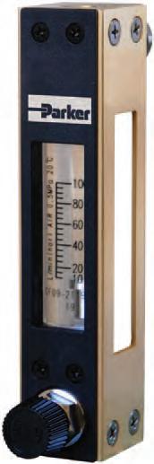
Product Features: • Valve can be placed in bottom or top position • Laser engraved graduations and magnifying lens make reading flow measurement scale quick and easy P260 Series Glass Tube Variable Area Flow Meter Contact Information: Parker Hannifin Corporation Porter Instrument Division 245 Township Line Road Hatfield, PA 19440 Phone 215 723 4000 Fax 215 723 2199 industrial@parker.com www.porterinstrument.com • Ideal for OEM applications • Standard ranges for N2, Air and water
The P260 Series flow meters are optimized for measuring low flow rates of water, air, and nitrogen, making it ideal for OEM applications. Laser engraved graduations and a magnifying lens provides users with a quick, precise, easy and accurate reading of the flow measurement scale.
Materials of Construction
Wetted
Body Standard: • SCS14 (equivalent to 316 SS)
Tapered Tube Heat-resistant Glass Float 304 Stainless Steel, Glass, PTFE or Ruby Packing
Standard: • NBR (Nitrile Rubber) Optional: • FPM (Fluorinated Propylene Monomer)
Non-wetted Support 6063-T5 Aluminum Front Panel Acrylonitrile Butadiene Styrene (ABS) Scale Panel Polycarbonate Connection Size and Type
Standard: • NPT or RC 1/4" with locknuts for front panel mounting
Dimensional
Performance
Flow Rate Scale Ranges
Water1 Minimum Maximum 0.1 - 0.8 Gal/h (0.3 - 3 L/h) 6.3 - 32 Gal/h (24–120 L/h) Air2 Minimum Maximum 0.02 - 2.1 ft3/h (6 - 60 L/h) (nor) 300 - 3000 ft3/h (720 - 3600 L/h) (nor) Turndown 10:1 Accuracy ±5% F.S. Approx. Weight 1.1 lbs. (0.5 kg) Flow Direction Bottom rear to top rear
Operating Conditions
Max. Operating Pressure 116 psig (8 barg) Max. Operating Temperature • NBR (Nitrile Rubber) • FPM (Fluorinated Propylene Monomer)
(1.3 in (30 mm)) Max 1 in (26 mm) (1.2 in (31 mm)) 0.7 in (17 mm) (5.5 in (140 mm)) 4.5 in (115 mm)
176°F (80°C) 248°F (120°C) 1 Liquid equivalent to water density 1.0g/cm3, viscosity 1.0cp 2 Gases equivalent to Air @ 0°C 1 atm 115
2 – NPT 1/4” 2 – M18
2 – ø 0.8 in (20 mm)
– d 2 – D 4.5 in (115 mm)
PANEL CUT OUT IN
Drawing Standard Type Valve Provided at Outlet Specifications
Standard
0.1 - 0.80.3 - 3 0.2 - 2.16 - 60 0.2 - 1.60.6 - 6 0.3 - 3.21.2 - 12 0.6 - 6.418 - 180 0.5 - 4.81.8 - 18 0.8 - 7.93 - 301.1 - 1130 - 300 1.6 - 166 - 60 2.1 - 2160 - 600 4.2 - 42120 - 1200 6.4 - 64180 - 1800 4.8 - 2418 - 908.5 - 85240 - 2400 6.3 - 3224 - 12011 - 106300 - 3000
Flow Capacity Ranges Flow Rate Table Water1 Air2 Gal/hL/hft3/hL/h (nor)
Ordering Information Model: P26 Flow / Direction 1 Bottom rear to top rear (standard) Air2 flow rates from 6 - 60 L/hr up to
L/hr Water1 flow rates from
Z Special Valve A None B Bottom C Top Z Special Alarm Output 1 None Z Special Wetted Parts B SCS14 (equivalent to 316 Stainless Steel) Z Special Packing Material 1Fluorinated Propylene Monomer (FPM/FKM) 2 Nitrile (NBR) Z Special Connection Type A NPT thread (standard) B RC thread (typical for non-USA market) Z Special Connection Size 2 1/4" (standard) Z Special Mounting Options A None (Standard with locknuts for front panel mounting) Z Special Example: P261 A1B1A2A 1 Liquid equivalent to water density 1.0g/cm3, viscosity 1.0cp 2 Gases equivalent to Air @ 0°C 1 atm Application Information
Settings
Other Options
1 Liquid equivalent to water density 1.0g/cm3, viscosity 1.0 cp 2 Gases equivalent to Air @ 0°C 1 atm
300 - 3000
0.3 - 3 L/hr up to 24 - 120 L/hr
Fluid Name: Operating Density or Specific Gravity: Viscosity: Flow Rate Maximum: Operating or Normal: Scale Range: Pressure Maximum: Operating or Normal: Temperature Maximum: Operating or Normal: Alarm
Alarm 1: Alarm 2:
WARNING – USER RESPONSIBILITY
FAILURE OR IMPROPER SELECTION OR IMPROPER USE OF THE PRODUCTS DESCRIBED HEREIN OR RELATED ITEMS CAN CAUSE DEATH, PERSONAL INJURY AND PROPERTY DAMAGE.
This document and other information from Parker-Hannifin Corporation, its subsidiaries and authorized distributors provide product or system options for further investigation by users having technical expertise.
The user, through its own analysis and testing, is solely responsible for making the final selection of the system and components and assuring that all performance, endurance, maintenance, safety and warning requirements of the application are met. The user must analyze all aspects of the application, follow applicable industry standards, and follow the information concerning the product in the current product catalog and in any other materials provided from Parker or its subsidiaries or authorized distributors.
To the extent that Parker or its subsidiaries or authorized distributors provide component or system options based upon data or specifications provided by the user, the user is responsible for determining that such data and specifications are suitable and sufficient for all applications and reasonably foreseeable uses of the components or systems.
Offer of Sale
The items described in this document are hereby offered for sale by Parker-Hannifin Corporation, its subsidiaries or its authorized distributors. This offer and its acceptance are governed by the provisions stated in the detailed “Offer of Sale” elsewhere in this document or available at www.parker.com/offerofsale.
Bulletin
Rev A 1/12
FM-1195
© 2009 Parker Hannifin Corporation
