The P210 Series flow meters are designed for low flow rates of both liquids and gases.
They cover a broad range of applications, from purging to monitoring of industrial processes.

The P210 Series offers 316 Stainless Steel construction for all wetted parts.
For challenging corrosive applications, the P210 offers PTFE seals as an option.
Product Features:
for general purpose use, as well as use for field test equipment
for both liquids and gases
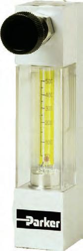
Stainless Steel construction for all wetted parts P210 Series Glass Tube Variable Area Flow Meter Contact Information: Parker Hannifin Corporation Porter Instrument Division 245 Township Line Road Hatfield, PA 19440 Phone 215 723 4000 Fax 215 723 2199 industrial@parker.com www.porterinstrument.com • PTFE seals are available as an option • Front panel mounting hardware • Easy-to-read scale • Scale tube length of 45mm • Optional alarm output
• Ideal
• Suitable
• 316
Specifications
Materials of Construction
Wetted
Body Standard: • 316 Stainless Steel Tapered Tube Heat-resistant Glass Float 316 Stainless Steel, Glass, PTFE or Ruby
Packing
Standard: • NBR (Nitrile Rubber) Optional: • FPM (Fluorinated Propylene Monomer) • CR (Neoprene)
• PTFE (Polytetrafluoroethylene)
Fitting Standard: • 316 Stainless Steel Valve Standard: • 316 Stainless Steel Non-wetted
Performance Flow Rate Scale Ranges
Water1 Minimum Maximum 0.1 - 0.8 Gal/h (0.3 - 3 L/h) 6.3 - 32 Gal/h (24–120 L/h) Air2 Minimum Maximum 0.01 - 0.04 ft3/h (0.2 - 1.2 L/h) (nor) 11 - 106 ft3/h (300 - 3000 L/h) (nor) Turndown 10:1 Accuracy ±5% F.S. Approx. Weight 1.1 lbs. (0.5 kg) Flow Direction Bottom rear to top rear Alarm Type Self-holding Reed Switch
Operating Conditions
Max. Operating Pressure
Max. Operating Temperature • NBR (Nitrile Rubber) • CR (Neoprene)
116 psig (8 barg) (72.5 psig) (5 barg) when PTFE packing material is used
• NPT or RC 1/4" with locknuts for front panel mounting
Reed Switch Specification
• PTFE (Polytetrafluoroethylene) • FPM (Fluorinated Propylene Monomer)
176°F (80°C) 176°F (80°C) 248°F (120°C) 248°F (120°C)
1Liquid equivalent to water density 1.0g/cm3, viscosity 1.0cp 2Gases equivalent to Air @ 0°C 1 atm
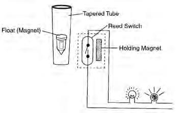
Contact Reed switch(Self-holding type)
Max. contact capacity: AC10VA, DC10W Max. voltage: AC125V, DC100V Max. current: 0.5A
Reset-Span 25% Full Scale Ambient Temperature -10°C to 60°C
Caution must be taken when mounting multiple alarmed meters. Close proximity may cause interference with alarm signal.
Cover Polycarbonate Support Aluminum Connection Size and Type Standard:
point
point
option
Number of Point 1
(High or Low) 2
alarm also available as an
Consult factory for details
Alarm Setting Range Standard 20% to 80% of full scale (H: 50% to 80%, L: 20% to 50%)
Connection Lead wire connection of 50cm (2m is also available)
Dimensional
1.4
mm)
Air1 Flow Rate Table
If LO, LC, HO, or HC Alarm Output Air Alarm Setting Range ft3/hL/h (nor)ft3/hL/h (nor) 0.1 - 1.1*3 - 300.2 - 0.86 - 24 0.2 - 2.16 - 600.4 - 1.712 - 48 0.4 - 4.212 - 1200.8 - 3.424 - 96 0.6 - 6.418 - 1801.3 - 5.136 - 144 1.3 - 1336 - 3602.1 - 1160 - 300 2.1 - 21**60 - 600**4.2 - 17120 - 480 6.4 - 32180 - 9006.4 - 25180 - 720 13 - 64360 - 180013 - 51360 - 1440 17 - 85480 - 240017 - 68480 - 1920
1 Air measured at 0 psig and 32°F (0°C)
When PTFE is used, a flow meter with a valve cannot be manufactured for a flow rate less than 2.1 ft3/h (60 L/h) (nor).
* 10:2 if range is less than 0.2 ft3/h (6 L/h) (nor)
** 10:2 if range is more than 21 ft3/h (600 L/h) (nor)
Water2 Flow Rate Table
If
0.1 - 0.80.3 - 30.2 - 0.60.6 - 2.4 0.2 - 1.60.6 - 60.3 - 1.31.2 - 4.8 0.8 - 3.23 - 121.3 - 2.54.8 - 9.6 0.5 - 4.81.8 - 181 - 3.83.6 - 14 0.8 - 7.93 - 301.6 - 6.36 - 24 1.6 - 16*6 - 603.2 - 1312 - 48
2 Water measured with viscosity of 1 mPas
* 10:2 if range is more than 16 Gal/h (60 L/h)
Drawing Standard valve provided at outlet, with locknuts for front panel mounting Use non-magnetized material for panel with Reed Switch alarm output (5.5 in (140 mm)) 4.5 in (115 mm) 4.5 in (115 mm)
(1.2 in (30 mm)) 1.4 in (35
0.7 in (19 mm) (Max
in (36 mm)) 2 – NPT 1/4” 2 – M18 Panel Max t 10 2 – ø 0.8 in (20 mm) PANEL CUT OUT IN Panel Cut Dimensions Connection Size Hole Diameter inmm 1/4" NPT or RCø 0.8ø 20.0 1/8" NPT or RCø 0.6ø 16.0
Flow Range Alarm Settings
LO, LC, HO, or HC Alarm Output Water Alarm Setting Range Gal/hL/hGal/hL/h
Ordering Information Model:
Bottom rear to top rear
Air2 flow rates >18 L/hr up to 1200 L/hr Water1 flow rates from 0.3-3 L/hr to 24 – 120 L/hr
Bottom rear to top rear Air2 flow rates <18 L/hr
Bottom rear to top rear Air2 flow rates >1200 L/hr up to 3000 L/hr
Application Information
Reed Switch – Contact closes (becomes ON) when value is more than set point
Reed Switch – Contact opens (becomes OFF) when value is more than set point
Reed Switch – Contact closes (becomes ON) when value is less than set point
Reed Switch – Contact opens (becomes OFF) when value is less than set point
Fluorinated Propylene Monomer (FPM/FKM)
Nitrile (NBR)
Neoprene (CR)
Polytetrafluoroethylene (PTFE)
RC thread (typical for non-USA market)
Fluid Name: Operating Density or Specific Gravity: Viscosity: Flow Rate Maximum: Operating or Normal: Scale Range: Pressure Maximum: Operating or Normal: Temperature Maximum: Operating or Normal: Alarm Settings Alarm 1: Alarm 2: Other Options
WARNING – USER RESPONSIBILITY
FAILURE OR IMPROPER SELECTION OR IMPROPER USE OF THE PRODUCTS DESCRIBED HEREIN OR RELATED ITEMS CAN CAUSE DEATH, PERSONAL INJURY AND PROPERTY DAMAGE.
This document and other information from Parker-Hannifin Corporation, its subsidiaries and authorized distributors provide product or system options for further investigation by users having technical expertise.
The user, through its own analysis and testing, is solely responsible for making the final selection of the system and components and assuring that all performance, endurance, maintenance, safety and warning requirements of the application are met. The user must analyze all aspects of the application, follow applicable industry standards, and follow the information concerning the product in the current product catalog and in any other materials provided from Parker or its subsidiaries or authorized distributors. To the extent that Parker or its subsidiaries or authorized distributors provide component or system options based upon data or specifications provided by the user, the user is responsible for determining that such data and specifications are suitable and sufficient for all applications and reasonably foreseeable uses of the components or systems.
Offer of Sale
The items described in this document are hereby offered for sale by Parker-Hannifin Corporation, its subsidiaries or its authorized distributors. This offer and its acceptance are governed by the provisions stated in the detailed “Offer of Sale” elsewhere in this document or available at www.parker.com/offerofsale.
Bulletin FM-1190 Rev A 1/12
© 2009 Parker Hannifin Corporation
P21
Flow / Direction 1
2
3
Z
A
C
Z
Special Valve
None B Bottom
Top
Special Alarm Output 1 None 2
4
Z
A
Z
Packing Material 1
2
3
4
Z Special Connection Type A
B
Z Special Connection Size 1
2
Z Special Mounting Options A None (standard with
for front panel mounting) Z Special Example: 211A1A1A1A 1 Liquid equivalent to water density 1.0g/cm3 , viscosity 1.0cp 2 Gases equivalent to Air @ 0°C 1 atm
3
5
Special Wetted Parts
316 Stainless Steel (Standard)
Special
NPT thread (standard)
1/8"
1/4"
locknuts
