

Parker R-max™ Stream Switching System Catalog 4140-R January 2010

ii
Catalog 4140-R R-max ™ Stream Switching System © Copyright 2010 Parker Hannifin Corporation.
Rights Reserved.
of Sale The items described in this document are hereby offered for sale by Parker-Hannifin Corporation, its subsidiaries or its authorized distributors. This offer and its acceptance are governed by the provisions stated in the detailed “Offer of Sale” elsewhere in this document or available at www.parker.com/ipdus. WARNING – USER RESPONSIBILITY FAILURE OR IMPROPER SELECTION OR IMPROPER USE OF THE PRODUCTS DESCRIBED HEREIN OR RELATED ITEMS CAN CAUSE DEATH, PERSONAL INJURY AND PROPERTY DAMAGE. This document and other information from Parker-Hannifin Corporation, its subsidiaries and authorized distributors provide product or system options for further investigation by users having technical expertise. The user, through its own analysis and testing, is solely responsible for making the final selection of the system and components and assuring that all performance, endurance, maintenance, safety and warning requirements of the application are met. The user must analyze all aspects of the application, follow applicable industry standards, and follow the information concerning the product in the current product catalog and in any other materials provided from Parker or its subsidiaries or authorized distributors. To the extent that Parker or its subsidiaries or authorized distributors provide component or system options based upon data or specifications provided by the user, the user is responsible for determining that such data and specifications are suitable and sufficient for all applications and reasonably foreseeable uses of the components or systems. Table of Contents Introduction ........................................................1 Features .............................................................1 Specifications .....................................................1 Flow Diagram – Three Stream Switching System...............................................1 Actuation Pressure vs. System Pressure ...........1 Valve Dimensions ..............................................2 Available End Connections ................................2 Valve Module Exploded View .............................3 Materials of Construction ...................................3 Valve Module .....................................................4 Valve Expansion Module – R2EM ......................4 Multi-Stream Switch – R2 ..................................5 Fast Loop Options ..............................................5 Multi-Stream Switch with GC Module –R2GC .................................................................6 Lab Sample Switch – R2LS ...............................7 How to Order ..................................................7 How to Order Stream Switching Systems and Accessories ................................................8 How to Order Addditional Options .....................8 How to Order Kits ...............................................8 Single Valve .......................................................9 Fast Loop Filters ................................................9 How to Order Fast Look Filters ....................10 Fast Loop Filter Options ...............................10 Offer of Sale .....................................................11
Parker Hannifin Corporation Instrumentation Products Division Huntsville, AL USA www.parker.com/icd
All
Offer
Introduction
The Parker R-max ™ is a multi-functional system capable of integrating both stream switching and filtering into one unique compact assembly. The system is designed to control both gases and liquids in analytical systems ranging from vacuum to 500 psig (34 bar) while requiring only 40 psig (3 bar) actuating air pressure. The system was engineered with a focus on improved product reliability and reduced cost of ownership. The Parker R-max ™ Stream Switching System utilizes state-of-the-art surface mount technology to reduce leak paths, internal volume, and dead volume. With surface mounting, system components may be easily removed and replaced without breaking process connections. In addition, the Parker R-max ™ system utilizes an internal self-purging outlet header to eliminate the need for an additional outlet loop.
Features
• Surface Mount Technology enhances maximum system flexibility and enables the user to add additional streams to a system without interrupting installed units.
• PCTFE Sealing Technology provides maximum sealing capability for both gases and liquids to eliminate leakage often found when using elastomeric O-ring seat designs.
• Low Internal Volume insures maximum system efficiency by reducing purge time and expensive purge gas.
• Modular Valve Design offers maximum service-ability for quick and easy in-system repair and reduced downtime.
• Internal Loop Design eliminates the need for an external loop and provides maximum capability with minimum system footprint.
• Visual Position Indicator enables the user to easily determine valve position for maximum system safety.
• Low Actuation Pressure design for maximum sealing capability with minimum air supply needs.
• Patent Pending.
Flow Data (In a two stream system)
Fluorocarbon Rubber -15°F to 400°F (-26°C to 204°C)
Buna-N Rubber -30°F to 275°F (-34°C to 135°C)
Ethylene Propylene Rubber -70°F to 275°F (-57°C to 135°C)
Neoprene Rubber -45°F to 250°F (-43°C to 121°C)
Highly Fluorinated Fluorocarbon Rubber -25°F to 200°F (-32°C to 93°C)
Stream 1: C v = 0.128; xT = 0.64 Stream 2: C v = 0.099; xT = 0.68 Tested in accordance with ISA S75.02. Gas flow will be choked when P1 - P2 / P1 = xT
1
Catalog 41404-R R-max ™ Stream Switching System SAMPLE INJECT VALVE VENT ACTUATION AIR "ON" VENT ACTUATION AIR AIR ACTUATION STREAM 2 END BLOCK STREAM 3 VENT STREAM 1 END BLOCK VENT
Parker Hannifin Corporation Instrumentation Products Division Huntsville, AL USA www.parker.com/icd
0100200300400500 07 14212834 0 10 20 30 40 50
Flow Diagram –Three Stream Switching System Actuation Pressure vs. System Pressure
0.0 0.7 1.4 2.0 2.7 3.4 System Pressure (bar) Actuator Pressure (psig) Actuator Pressure (bar) System Pressure (psig) System shown with Stream 2 open to the sample inject valve Specifications Item Material Pressure Rating 500 psig (34 bar) CWP Temperature Ratings
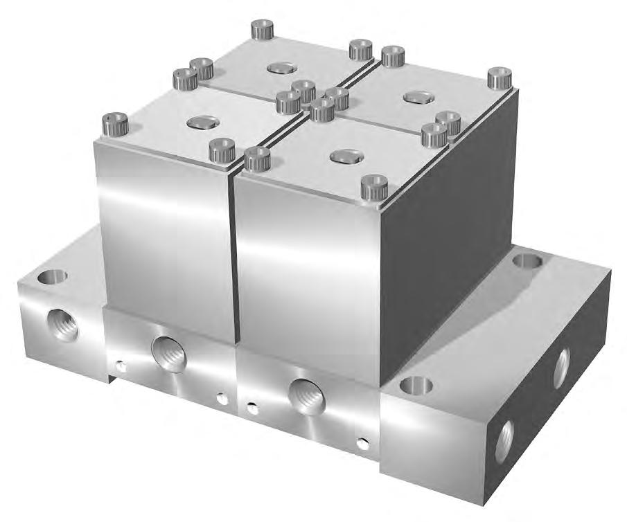
2 Parker Hannifin Corporation Instrumentation Products Division Huntsville, AL USA www.parker.com/icd Catalog 4140-R R-max ™ Stream Switching System Stream 2 Actuation Air Inlet Easy Maintenance Using Surface Mount Technology Visual Valve Position Indicator Stream 1 Actuation Air Inlet Support Bracket Mounting Provisions Outlet (To Analyzer) Return (From Analyzer) Vent Port (Both Sides) Panel Mountable Using 1/4" Bolts Stream Inlets In Each Module (Not Shown) Factory Assembled Two Module Stream Switching System See How to Order – Page 8 1.13 (28.7) 1.46 (37.1) Typ .75 (19.1) 1.00 (25.4) 2.91 (73.9) 2.56 (65.0) 2.77 (70.4) .86 (21.8) Available End Connections 2F – 1/8" ANSI/ASME B1.20.1 Internal pipe threads 4A7 – 1/4" Inverted two ferrule A-LOK® compression port 4Z7 – 1/4" Inverted single ferrule CPI™ compression port Note: Actuator air porting and vent porting is always 1/8" FNPT Valve Dimensions ( ) Denotes dimensions in millimeters
Materials of Construction ItemPart DescriptionStainless Steel Alloy N04400
Base ASTM A 479, Type 316ASTM B 127, Alloy N04400
Valve BodyASTM A 479, Type 316ASTM B 127, Alloy N04400
Stem ASTM A 479, Type 316ASTM B 127, Alloy N04400
Lower BonnetASTM A 479, Type 316ASTM B 164, Alloy N04405
Upper BonnetASTM A 479, Type 316ASTM B 164, Alloy N04405
Cap Bolt ASTM A 193, Grade B8 Note: Material for Stream Switching Vent and Analyzer End Plates (not shown) is ASTM A 479, Type 316 or ASTM B 127, Alloy N04400. Material for Base Plate Bolts is ASTM A 276, Type 316. Lubrication: Perfluorinated polyether
3
Catalog 41404-R R-max ™ Stream Switching System
Parker Hannifin Corporation Instrumentation Products Division Huntsville, AL USA www.parker.com/icd
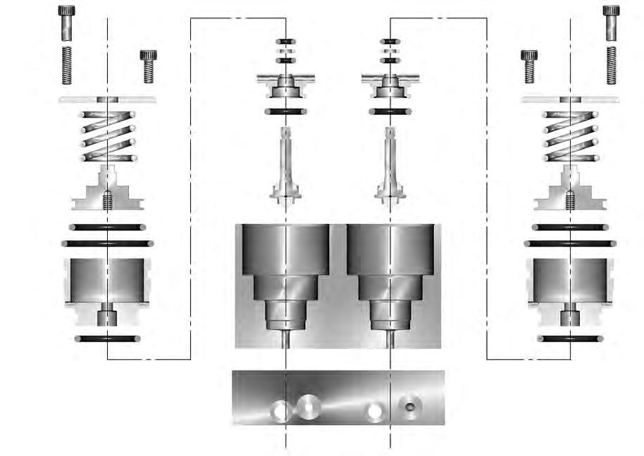
Valve Module Exploded View
3
4
5
6
7
8
9
10
11
12
13
14
15
16
17
18
1 4 5 3 6 8 7 8 8 9
10 12 14 11 13 16 15 17 18 18 11 10 12 15 17 14 13 16
1
2
Lower Seat PCTFE
Upper Seat PCTFE
O-Ring 2-013 Optional Elastomers
O-Ring 2-007 Optional Elastomers
Back-up Ring PTFE
O-Ring 2-018 Optional Elastomers
O-Ring 2-023 Optional Elastomers
Piston ASTM B 211, Alloy 6061
O-Ring 2-020 Optional Elastomers
Spring ASTM A 564, Type 630
Cap ASTM A 479, Type 316
Body Bolt ASTM A 193, Grade B8
2
R-max ™ Stream Switching System
Valve Module
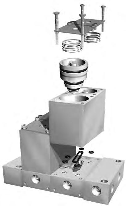
The Parker R-max ™ Stream Switching System centers around the Valve Module, which contains two 3-way valves. Each Valve Module is factory mounted to a Base Plate configured to provide the desired function. The Stream Switching Valve Module provides a double block and bleed arrangement preventing cross contamination of sample streams.
Valve Module Features
• Each Valve Module has a flow inlet and outlet (1/8" FNPT or 1/4" Inverted Compression) and a 1/8" FNPT valve air actuation port.
• Each Valve Module employs two valves.
Valve Module Flow Diagram
Valve Expansion Module – R2EM
Valve Expansion Modules may be added or removed from the Parker R-max ™ Stream Switching System. The Valve Expansion Module consists of a Valve Module plus two Base Plate Bolts. They may be inserted between the Vent and Analyzer End Plates to add one or more streams to a system. (See How to Order on Page 8.)
Note: Valve Modules may only be added to an existing stream switching system. Easy Surface Mount/Module Disassembly
4
Catalog 4140-R
Parker Hannifin Corporation Instrumentation Products Division Huntsville, AL USA
www.parker.com/icd
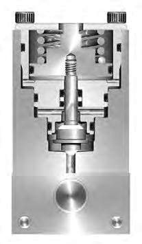
VENT VENT INLET "ON" INLET "OFF" OUTLET OUTLET
Valve Module Cross Section
Multi-Stream Switch – R2
Fast Loop Options
Internal Fast Loop
Example shown is a three stream switching system with an internal fast loop that maintains the double block and bleed feature. Illustrates Streams 1 and 3 in the “Off” position, with these two streams flowing to the common vent. Stream 2 is illustrated in the “On” position, closing the bypass and directing the flow to the analyzer. To order, add the suffix -IF to the end of the Stream Switching System part number (See How to Order – Page 9)
A Multi-Stream Switch consists of individual Valve Modules bolted together between Vent and Analyzer End Plates to create an internal, self-purging system with an integral outlet header. This unique design eliminates dead volume and the need for an external loop. ACTUATION
Example: 2F-R2K-BN-SS-3-IF
External Fast Loop Kits
Example shown is a three stream switching system with an external fast loop. External Bypass Kits are available to adapt to the standard Parker R-max ™ Stream Switching System. The bypass option maintains the double block and bleed feature of the Parker R-max ™ System.
Order: KIT-R2-Fitting Part Number-EF
Example: KIT-R2-2MRT2N-316-EF
Fast Loop Filters
Example shown is a three stream switching system with two filter bypasses. Bypass Filter Kits may be incorporated into the Parker R-max ™ Stream Switching System to enhance your system design.
How to Order: See Page 10
Parker Hannifin Corporation Instrumentation Products Division Huntsville, AL USA www.parker.com/icd
5
Catalog 41404-R
R-max ™ Stream Switching System
AIR "ON" VENT ACTUATION AIR AIR ACTUATION STREAM 2 STREAM 3 VENT STREAM 1 END BLOCK SAMPLE INJECT VALVE VENT END BLOCK VENT
MEDIA MEDIA BYPASS
VENT ACTUATION
BYPASS
ACTUATION AIR "ON"
AIR AIR ACTUATION VENT STREAM 3 STREAM 2 VENT STREAM 1 END BLOCK SAMPLE INJECT VALVE VENT END BLOCK
SAMPLE INJECT VALVE VENT EXTERNAL BYPASSBYPASS EXTERNALEXTERNAL BYPASS ACTUATION AIR "ON" VENT ACTUATION AIR AIR ACTUATION STREAM 2 STREAM 3 VENT STREAM 1 END BLOCK END BLOCK VENT
System
Multi-Stream Switch with GC Module – R2GC
The GC Module is positioned between the analyzer and stream switching system and is used to equilibrate the sample loop pressure to atmospheric pressure just prior to the sample injection. This insures a constant sample pressure in repetitive analyses. When the GC is actuated, the sample from the GC is routed to the low pressure vent.
GC Module Function – Three Stream Examples
Example 1
All valves are in the “Off” position. The system is “Open” to vent.
VENT
STREAM 1 STREAM 2 LOW PRESSURE HEADER
VENTACTUATION AIR
STREAM 3 ACTUATION ACTUATION AIR AIR ACTUATION AIR
Example 2
Stream 2 and the GC Module are in the “On” position, purging the sample loop to the low pressure header.
VENT
STREAM 1 STREAM 2 LOW PRESSURE HEADER
GC SAMPLE INJECT VALVE
VENTACTUATION AIR
STREAM 3 ACTUATION ACTUATION AIR AIR ACTUATION AIR
Example 3
Stream 2 is in the “On” position and the GC Module is in the “Off” position, equilibrating the sample loop pressure to vent pressure.
VENT
STREAM 3
STREAM 1 STREAM 2 LOW PRESSURE HEADER
GC SAMPLE INJECT VALVE
GC SAMPLE INJECT VALVE
VENTACTUATION AIR
ACTUATION ACTUATION AIR AIR ACTUATION AIR
Parker Hannifin Corporation Instrumentation Products Division Huntsville, AL USA www.parker.com/icd
6
Catalog 4140-R
R-max ™ Stream Switching
GC
VENT GC MODULE TO
STREAM SWITCH STREAM SWITCH Example Shown: Two streams with GC Module
Lab Sample Switch – R2LS
Process stream samples are often collected and analyzed by laboratory personnel to calibrate or verify the accuracy of the process analyzer. The Laboratory Sample Switch is installed in the sample stream on the outlet of the analyzer. The switch is used to route the sample flow to and from a sample container without disturbing or interrupting the analyzer sample flow. Complete Lab Sample Station Kits are also available.
How to Order
Lab Sample Switch
Order: 2F-R2LSK-Seal Material-Body Material
Consists of:
One Parker R-max ™ Lab Station Switch
Example: 2F-R2LSK-V-SS
Complete Lab Sample Station Kit
Order: KIT-R2LS-Cylinder Size and MaterialHose Material
Consists of:
• Two Connectors
• Two 3-way Ball Valves with PTFE Seats and Seals
• Two Quick Disconnect Couplers with Fluorocarbon Seals
• Two Quick Disconnect Nipples with Fluorocarbon Seals
• One Gauge Port Tee;
• One Sample Cylinder Isolation Needle Valve with PTFE Packing;
• One Sample Cylinder Isolation Needle Valve with integral Rupture Disc and PTFE Packings and Seals;
• One Sample Cylinder (150, 300, or 1000cc) in Aluminum (A) or Stainless Steel (SS);
• One Hose Assembly in Stainless Steel (SS) or PTFE (T)
Example: KIT-R2LS-150SS-SS
7
www.parker.com/icd Catalog 41404-R R-max ™ Stream Switching System
CYLINDER
INLET OUTLET INLET CYLINDER TO CYLINDER SAMPLE CYLINDER FROM
OUTLET CYLINDER SAMPLE CYLINDER TO CYLINDER
Parker Hannifin Corporation Instrumentation Products Division Huntsville, AL USA
PLUGGED PORT FROM
OUTLET INLET TO CYLINDER
"OFF"
FROM "ON"
How to Order Stream Switching Systems and Accessories
The correct part number is easily derived by following the circled number sequence. The seven product characteristics required are coded as shown below.
End Connection Valve Series Seat Material Base Option Body Material*
Seal Material
Number of Modules**
Example 1: 2F – R2 K – V – SS – 2
Describes a complete two stream switching system having 1/8" female NPT inlet and outlet ports, PCTFE valve seats, fluorocarbon rubber seals, and stainless steel construction.
Example 2: 2F – R2 GC K – EPR – SS – 4
Describes a complete four stream switching system with GC Module having 1/8" female NPT inlet and outlet ports, PCTFE valve seats, ethylene propylene rubber seals, and stainless steel construction.*
End Connection Valve Series
2F 4A7 4Z7
R2 Blank None
Base Option
GC GC Service
LS Lab Switch
EM Valve Expansion Module S Single Valve
*Alloy N04400 not available on Single Valve units
Seat Material
Seal Material
K – PCTFE V Fluorocarbon Rubber
BN Buna-N Rubber
EPR Ethylene Propylene Rubber
NE Neoprene Rubber
KZ Highly Fluorinated Fluorocarbon Rubber
**The number of stream modules should not include a GC module in the count if ordered as part of the system.
How to Order Additional Options
Body Material*
Number of Modules**
SS Stainless Steel M Alloy N04400 Numeric Value Blank – LS, EM or S Base Option
Oxygen Cleaning - Add the suffix -C3 to the end of the part number to receive stream switching systems or accessories cleaned and assembled for oxygen service in accordance with Parker Specification ES8003.
Example: 4A7-R2K-V-SS-3-C3
How to Order Kits
Stem Seal Kits: KIT-R2K-Seal Material-Body Material. Example: KIT-R2K-V-SS. (Consists of one stem with PCTFE upper and lower seats, Fluorocarbon O-rings and associated PTFE back-up rings, and maintenance instructions.)
Valve Cartridge Kits: KIT-R2K-CART-Seal Material-Body Material. Example: KIT-R2K-CART-V-SS. (Consists of one completely assembled valve cartridge and maintenance instructions – Items 3 through 13 from Page 4 Materials of Construction.)
Silcosteel®: Add the suffix -RTK to the end of the part number to receive Stream Switching Valves with a thin, permanently bonded silicon based coating which shields sample analytes from adsorption.
Silcosteel is a registered trademark of Restek Corporation.
Parker Hannifin Corporation
Instrumentation Products Division Huntsville, AL USA www.parker.com/icd
8
Catalog 4140-R R-max ™
Stream Switching System
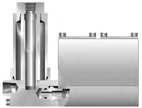
Single Valve
Features
• Surface Mount Technology
• PCTFE Sealing Technology
• Low Internal Volume
• Modular Design
• Visual Position Indicator
• Low Actuation Pressure
R-max ™ Stream Switching System
Designed to be used on the stream inlet ports of the Parker R-max ™ Stream Switching System to provide reduced transport time of filtered sample stream media from the process line through the stream switch to the analyzer. This is achieved by diverting approximately 90% of the inlet flow around the cartridge filter and out of the filter bowl.
ø1.25 (31.8) 1.40 (35.6)
1.44 (36.6)
Parker Hannifin Corporation Instrumentation Products Division Huntsville, AL USA www.parker.com/icd
9
Catalog 41404-R
OUTLET
1/8" FNPT PORT
The Parker R-max ™ Single Valve shares the same technology, features, and options found in the Stream Switching System. The pneumatically actuated valve serves as a three-way diverting valve with common, normally open, and normally closed porting. Filter installed on Stream 1 of a Three Stream System FAST LOOP OUTLET INLET
TO R-MAX 3.76 (95.5) 2.00 (50.8)
1.00 FLATS (25.4)
Fast Loop Filters
Materials of Construction
Bowl ASTM A 479, Type 316
AdapterASTM A 479, Type 316
Body BoltASTM A 193, Grade B8
How to Order Fast Loop Filters
Fast Loop Filter Options
10
Catalog 4140-R R-max ™ Stream Switching System
Parker Hannifin Corporation Instrumentation Products Division Huntsville, AL USA www.parker.com/icd
Fast Loop Filters
Silcosteel®: Add the suffix -RTK to the end of the part number to receive Filters with a thin, permanently bonded silicon based coating which shields sample analytes from adsorption.
2 3 4 5 6 7 8 1
Flow
the
vary according to the
type
Silcosteel is a registered trademark of Restek Corporation.
Note:
paths in
filter body
element
and are not shown.
ItemPart Description Material
2
3
4
5
6
7
8
1 Body ASTM A 479, Type 316
O-Ring 2-008Optional Elastomers
O-Ring 2-025Optional Elastomers
Element 316SS and Microfibre
Support Core 316SS
Inlet and Bypass Outlet Filter Series Element Type Filtration Type O-Ring Seals Body Material Example 1: 2F – FR2 – EPR – S 100 – SS – B Describes a FR2 Series Fast Loop Filter with 1/8" FNPT inlet and bypass outlets, ethylene propylene rubber seals,
sintered metal filter element, stainless steel construction, and designed to be attached to a Parker R-max ™ Stream Switch having inverted CPI™ or A-LOK® stream inlet ports. R-max ™ Connection Type Inlet and Outlet Bypass Outlet Filter Series O-Ring Seals Filtration Type Element Type Body Material* R-max ™ Connection Type Balston® P and C Sintered Metal (S) 2F 1/8" Female NPT FR2 V Fluorocarbon Rubber BN Buna-N Rubber EPR Ethylene Propylene Rubber NE Neoprene Rubber KZ Highly Fluorinated Fluorocarbon Rubber P Particulate C Coalescing S Sintered Metal 93 93% Microfibre 99 99% Microfibre 100 100 micron 70 70 micron 40 40 micron 20 20 micron 10 10 micron 5 5 micron SS Stainless Steel A 2F B 4A7 or 4Z7
The correct part number is easily derived by following the circled number sequence. The seven product characteristics required are coded as shown below.
100 micron 316SS
Offer of Sale
Offer of Sale
The items described in this document and other documents and descriptions provided by Parker Hannifin Corporation, its subsidiaries and its authorized distributors (“Seller”) are hereby offered for sale at prices to be established by Seller. This offer and its acceptance by any customer (“Buyer”) shall be governed by all of the following Terms and Conditions. Buyer’s order for any item described in its document, when communicated to Seller verbally, or in writing, shall constitute acceptance of this offer. All goods or work described will be referred to as “Products”.
1. Terms and Conditions. Seller’s willingness to offer Products, or accept an order for Products, to or from Buyer is expressly conditioned on Buyer’s assent to these Terms and Conditions and to the terms and conditions found on-line at www.parker.com/saleterms/. Seller objects to any contrary or additional term or condition of Buyer’s order or any other document issued by Buyer.
2. Price Adjustments; Payments. Prices stated on the reverse side or preceding pages of this document are valid for 30 days. After 30 days, Seller may change prices to reflect any increase in its costs resulting from state, federal or local legislation, price increases from its suppliers, or any change in the rate, charge, or classification of any carrier. The prices stated on the reverse or preceding pages of this document do not include any sales, use, or other taxes unless so stated specifically. Unless otherwise specified by Seller, all prices are F.O.B. Seller’s facility, and payment is due 30 days from the date of invoice. After 30 days, Buyer shall pay interest on any unpaid invoices at the rate of 1.5% per month or the maximum allowable rate under applicable law.
3. Delivery Dates; Title and Risk; Shipment. All delivery dates are approximate and Seller shall not be responsible for any damages resulting from any delay. Regardless of the manner of shipment, title to any products and risk of loss or damage shall pass to Buyer upon tender to the carrier at Seller’s facility (i.e., when it’s on the truck, it’s yours). Unless otherwise stated, Seller may exercise its judgment in choosing the carrier and means of delivery. No deferment of shipment at Buyers’ request beyond the respective dates indicated will be made except on terms that will indemnify, defend and hold Seller harmless against all loss and additional expense. Buyer shall be responsible for any additional shipping charges incurred by Seller due to Buyer’s changes in shipping, product specifications or in accordance with Section 13, herein.
4. Warranty. Seller warrants that the Products sold hereunder shall be free from defects in material or workmanship for a period of twelve months from the date of delivery to Buyer or 2,000 hours of normal use, whichever occurs first. This warranty is made only to Buyer and does not extend to anyone to whom Products are sold after purchased from Seller. The prices charged for Seller’s products are based upon the exclusive limited warranty stated above, and upon the following disclaimer: DISCLAIMER OF WARRANTY: THIS WARRANTY COMPRISES THE SOLE AND ENTIRE WARRANTY PERTAINING TO PRODUCTS PROVIDED HEREUNDER. SELLER DISCLAIMS ALL OTHER WARRANTIES, EXPRESS AND IMPLIED, INCLUDING MERCHANTABILITY AND FITNESS FOR A PARTICULAR PURPOSE.
5. Claims; Commencement of Actions. Buyer shall promptly inspect all Products upon delivery. No claims for shortages will be allowed unless reported to the Seller within 10 days of delivery. No other claims against Seller will
be allowed unless asserted in writing within 60 days after delivery or, in the case of an alleged breach of warranty, within 30 days after the date within the warranty period on which the defect is or should have been discovered by Buyer. Any action based upon breach of this agreement or upon any other claim arising out of this sale (other than an action by Seller for any amount due to Seller from Buyer) must be commenced within thirteen months from the date of tender of delivery by Seller or, for a cause of action based upon an alleged breach of warranty, within thirteen months from the date within the warranty period on which the defect is or should have been discovered by Buyer.
6. LIMITATION OF LIABILITY. UPON NOTIFICATION, SELLER WILL, AT ITS OPTION, REPAIR OR REPLACE A DEFECTIVE PRODUCT, OR REFUND THE PURCHASE PRICE. IN NO EVENT SHALL SELLER BE LIABLE TO BUYER FOR ANY SPECIAL, INDIRECT, INCIDENTAL OR CONSEQUENTIAL DAMAGES ARISING OUT OF, OR AS THE RESULT OF, THE SALE, DELIVERY, NON-DELIVERY, SERVICING, USE OR LOSS OF USE OF THE PRODUCTS OR ANY PART THEREOF, OR FOR ANY CHARGES OR EXPENSES OF ANY NATURE INCURRED WITHOUT SELLER’S WRITTEN CONSENT, EVEN IF SELLER HAS BEEN NEGLIGENT, WHETHER IN CONTRACT, TORT OR OTHER LEGAL THEORY. IN NO EVENT SHALL SELLER’S LIABILITY UNDER ANY CLAIM MADE BY BUYER EXCEED THE PURCHASE PRICE OF THE PRODUCTS.
7. Contingencies. Seller shall not be liable for any default or delay in performance if caused by circumstances beyond the reasonable control of Seller.
8. User Responsibility. The user, through its own analysis and testing, is solely responsible for making the final selection of the system and Product and assuring that all performance, endurance, maintenance, safety and warning requirements of the application are met. The user must analyze all aspects of the application and follow applicable industry standards and Product information. If Seller provides Product or system options, the user is responsible for determining that such data and specifications are suitable and sufficient for all applications and reasonably foreseeable uses of the Products or systems.
9. Loss to Buyer’s Property. Any designs, tools, patterns, materials, drawings, confidential information or equipment furnished by Buyer or any other items which become Buyer’s property, may be considered obsolete and may be destroyed by Seller after two consecutive years have elapsed without Buyer placing an order for the items which are manufactured using such property. Seller shall not be responsible for any loss or damage to such property while it is in Seller’s possession or control.
10. Special Tooling. A tooling charge may be imposed for any special tooling, including without limitation, dies, fixtures, molds and patterns, acquired to manufacture Products.
Parker Hannifin Corporation Instrumentation Products Division Huntsville, AL USA www.parker.com/icd
11
Catalog 41404-R
Offer of Sale
Such special tooling shall be and remain Seller’s property notwithstanding payment of any charges by Buyer. In no event will Buyer acquire any interest in apparatus belonging to Seller which is utilized in the manufacture of the Products, even if such apparatus has been specially converted or adapted for such manufacture and notwithstanding any charges paid by Buyer. Unless otherwise agreed, Seller shall have the right to alter, discard or otherwise dispose of any special tooling or other property in its sole discretion at any time.
11. Buyer’s Obligation; Rights of Seller. To secure payment of all sums due or otherwise, Seller shall retain a security interest in the goods delivered and this agreement shall be deemed a Security Agreement under the Uniform Commercial Code. Buyer authorizes Seller as its attorney to execute and file on Buyer’s behalf all documents Seller deems necessary to perfect its security interest. Seller shall have a security interest in, and lien upon, any property of Buyer in Seller’s possession as security for the payment of any amounts owed to Seller by Buyer.
12. Improper use and Indemnity. Buyer shall indemnify, defend, and hold Seller harmless from any claim, liability, damages, lawsuits, and costs (including attorney fees), whether for personal injury, property damage, patent, trademark or copyright infringement or any other claim, brought by or incurred by Buyer, Buyer’s employees, or any other person, arising out of: (a) improper selection, improper application or other misuse of Products purchased by Buyer from Seller; (b) any act or omission, negligent or otherwise, of Buyer; (c) Seller’s use of patterns, plans, drawings, or specifications furnished by Buyer to manufacture Product; or (d) Buyer’s failure to comply with these terms and conditions. Seller shall not indemnify Buyer under any circumstance except as otherwise provided.
13. Cancellations and Changes. Orders shall not be subject to cancellation or change by Buyer for any reason, except with Seller’s written consent and upon terms that will indemnify, defend and hold Seller harmless against all direct, incidental and consequential loss or damage. Seller may change product features, specifications, designs and availability with notice to Buyer.
14. Limitation on Assignment. Buyer may not assign its rights or obligations under this agreement without the prior written consent of Seller.
15. Entire Agreement. This agreement contains the entire agreement between the Buyer and Seller and constitutes the final, complete and exclusive expression of the terms of the agreement. All prior or contemporaneous written or oral agreements or negotiations with respect to the subject matter are herein merged.
16. Waiver and Severability. Failure to enforce any provision of this agreement will not waive that provision nor will any such failure prejudice Seller’s right to enforce that provision in the future. Invalidation of any provision of this agreement by legislation or other rule of law shall not invalidate any other provision herein. The remaining provisions of this agreement will remain in full force and effect.
17. Termination. This agreement may be terminated by Seller for any reason and at any time by giving Buyer thirty (30) days written notice of termination. In addition, Seller may
by written notice immediately terminate this agreement for the following: (a) Buyer commits a breach of any provision of this agreement (b) the appointment of a trustee, receiver or custodian for all or any part of Buyer’s property (c) the filing of a petition for relief in bankruptcy of the other Party on its own behalf, or by a third party (d) an assignment for the benefit of creditors, or (e) the dissolution or liquidation of the Buyer.
18. Governing Law. This agreement and the sale and delivery of all Products hereunder shall be deemed to have taken place in and shall be governed and construed in accordance with the laws of the State of Ohio, as applicable to contracts executed and wholly performed therein and without regard to conflicts of laws principles. Buyer irrevocably agrees and consents to the exclusive jurisdiction and venue of the courts of Cuyahoga County, Ohio with respect to any dispute, controversy or claim arising out of or relating to this agreement. Disputes between the parties shall not be settled by arbitration unless, after a dispute has arisen, both parties expressly agree in writing to arbitrate the dispute.
19. Indemnity for Infringement of Intellectual Property Rights. Seller shall have no liability for infringement of any patents, trademarks, copyrights, trade dress, trade secrets or similar rights except as provided in this Section. Seller will defend and indemnify Buyer against allegations of infringement of U.S. patents, U.S. trademarks, copyrights, trade dress and trade secrets (“Intellectual Property Rights”). Seller will defend at its expense and will pay the cost of any settlement or damages awarded in an action brought against Buyer based on an allegation that a Product sold pursuant to this Agreement infringes the Intellectual Property Rights of a third party. Seller’s obligation to defend and indemnify Buyer is contingent on Buyer notifying Seller within ten (10) days after Buyer becomes aware of such allegations of infringement, and Seller having sole control over the defense of any allegations or actions including all negotiations for settlement or compromise. If a Product is subject to a claim that it infringes the Intellectual Property Rights of a third party, Seller may, at its sole expense and option, procure for Buyer the right to continue using the Product, replace or modify the Product so as to make it noninfringing, or offer to accept return of the Product and return the purchase price less a reasonable allowance for depreciation. Notwithstanding the foregoing, Seller shall have no liability for claims of infringement based on information provided by Buyer, or directed to Products delivered hereunder for which the designs are specified in whole or part by Buyer, or infringements resulting from the modification, combination or use in a system of any Product sold hereunder. The foregoing provisions of this Section shall constitute Seller’s sole and exclusive liability and Buyer’s sole and exclusive remedy for infringement of Intellectual Property Rights.
20. Taxes. Unless otherwise indicated, all prices and charges are exclusive of excise, sales, use, property, occupational or like taxes which may be imposed by any taxing authority upon the manufacture, sale or delivery of Products.
21. Equal Opportunity Clause. For the performance of government contracts and where dollar value of the Products exceed $10,000, the equal employment opportunity clauses in Executive Order 11246, VEVRAA, and 41 C.F.R. §§ 601.4(a), 60-741.5(a), and 60-250.4, are hereby incorporated.
Parker Hannifin Corporation Instrumentation Products Division Huntsville, AL USA www.parker.com/icd
12
Catalog 4140-R
01/09
At Parker, we’re guided by a relentless drive to help our customers become more productive and achieve higher levels of profitability by engineering the best systems for their requirements. It means looking at customer applications from many angles to find new ways to create value. Whatever the motion and control technology need, Parker has the experience, breadth of product and global reach to consistently deliver. No company knows more about motion and control technology than Parker. For further info call 1-800-C-Parker.
AEROSPACE
Key Markets
• Aircraft engines
• Business & general aviation
• Commercial transports
• Land-based weapons systems

• Military aircraft
• Missiles & launch vehicles
• Regional transports
• Unmanned aerial vehicles
Key Products
• Flight control systems & components


• Fluid conveyance systems

• Fluid metering delivery & atomization devices
• Fuel systems & components

• Hydraulic systems & components
• Inert nitrogen generating systems
• Pneumatic systems & components
• Wheels & brakes
CLIMATE CONTROL
Key Markets
• Agriculture
• Air conditioning
• Food, beverage & dairy

• Life sciences & medical
• Precision cooling
• Processing
• Transportation
Key Products
• CO2 controls
• Electronic controllers
• Filter driers
• Hand shut-off valves
• Hose & fittings
• Pressure regulating valves
• Refrigerant distributors
• Safety relief valves
• Solenoid valves
• Thermostatic expansion valves
ELECTROMECHANICAL
Key Markets
• Aerospace
• Factory automation
• Life science & medical
• Machine tools
• Packaging machinery • Paper machinery • Plastics machinery & converting • Primary metals
• Semiconductor & electronics • Textile • Wire & cable
Key Products
AC/DC drives & systems
Electric actuators, gantry robots & slides • Electrohydrostatic actuation systems • Electromechanical actuation systems • Human machine interface
Linear motors • Stepper motors, servo motors, drives & controls • Structural extrusions
FILTRATION
Key Markets
• Food & beverage
• Industrial machinery
• Life sciences
• Marine
• Mobile equipment
• Oil & gas

• Power generation
• Process
• Transportation
Key Products
• Analytical gas generators

• Compressed air & gas filters
• Condition monitoring
• Engine air, fuel & oil filtration & systems
• Hydraulic, lubrication & coolant filters
• Process, chemical, water & microfiltration filters
• Nitrogen, hydrogen & zero air generators
PNEUMATICS
Key
Life science & medical
Machine tools
Key

•
•
•
•
•
•
Markets • Aerospace • Conveyor & material handling • Factory automation
Packaging machinery • Transportation & automotive
Pneumatic valves & controls • Quick disconnects • Rotary actuators • Rubber & thermoplastic hose & couplings • Structural extrusions • Thermoplastic tubing & fittings • Vacuum generators, cups & sensors FLUID & GAS HANDLING Key Markets • Aerospace • Agriculture • Bulk chemical handling • Construction machinery • Food & beverage • Fuel & gas delivery • Industrial machinery • Mobile • Oil & gas • Transportation • Welding Key Products • Brass fittings & valves • Diagnostic equipment • Fluid conveyance systems • Industrial hose • PTFE & PFA hose, tubing & plastic fittings • Rubber & thermoplastic hose & couplings • Tube fittings & adapters • Quick disconnects HYDRAULICS Key Markets • Aerospace • Aerial lift • Agriculture • Construction machinery • Forestry • Industrial machinery • Mining • Oil & gas • Power generation & energy • Truck hydraulics Key Products • Diagnostic equipment • Hydraulic cylinders & accumulators • Hydraulic motors & pumps • Hydraulic systems • Hydraulic valves & controls • Power take-offs • Rubber & thermoplastic hose & couplings • Tube fittings & adapters • Quick disconnects PROCESS CONTROL Key Markets • Chemical & refining • Food, beverage & dairy • Medical & dental • Microelectronics • Oil & gas • Power generation Key Products • Analytical sample conditioning products & systems • Fluoropolymer chemical delivery fittings, valves & pumps • High purity gas delivery fittings, valves & regulators • Instrumentation fittings, valves & regulators • Medium pressure fittings & valves • Process control manifolds SEALING & SHIELDING Key Markets • Aerospace • Chemical processing • Consumer • Energy, oil & gas • Fluid power • General industrial • Information technology • Life sciences • Military • Semiconductor • Telecommunications • Transportation Key Products • Dynamic seals • Elastomeric o-rings • EMI shielding • Extruded & precision-cut, fabricated elastomeric seals • Homogeneous & inserted elastomeric shapes • High temperature metal seals • Metal & plastic retained composite seals • Thermal management Parker’s Motion & Control Technologies
Products • Air preparation • Brass fittings & valves • Manifolds • Pneumatic accessories • Pneumatic actuators & grippers •
Sales Offices Worldwide
Parker Hannifin Corporation
Instrumentation Products Division 1005 A Cleaner Way Huntsville, AL 35805 USA phone 256 881 2040 fax 256 8815072 www.parker.com/ipdus
Parker Hannifin Corporation Instrumentation Products Division 2651 Alabama Highway 21 North Jacksonville, AL 36265-681 USA phone 256 435 2130 fax 256 435 7718 www.parker.com/ipdus
Parker Hannifin Corporation Instrumentation Products Division 6575 Tram Road Beaumont, TX 77713 USA phone 409 924 0300 fax 409 924 0301 www.parker.com/ipdus
Parker Hannifin plc Instrumentation Products Division Riverside Road Pottington Business Park Barnstaple, Devon EX31 1NP England phone +44 0 1271 313131 fax +44 0 1271 373636 email ipd@parker.com www.parker.com/ipd
Parker Hannifin Corporation
Instrumentation Products Division 2651 Alabama Highway 21 North Jacksonville, AL 36265-681 phone 256 435 2130 fax 256 435 7718 www.parker.com/ipdus
Your Local Authorized Parker Distributor Catalog 4140-R January 2010 DP
