


This document is intended to be a resource for Central Yavapai Metropolitan Planning Organization’s (CYMPO) member agencies to plan for and implement bicycle facilities improvements. The CYMPO Bicycle Facility Design Toolkit provides an overview of the types of bicycle facilities recommended in the CYMPO Active Transportation Plan (ATP).
The toolkit’s purpose is to provide guidance to designers and planners and is not intended to take the place of design standards prepared by the local jurisdictions or Arizona Department of Transportation. The planning, designing, and implementation of bicycle facilities should still follow the region’s rigorous process for selecting, engineering assessment, and public engagement.

• Provide comfortable and connected multimodal facilities for users of all ages and abilities;
• Bicycle travel on all streets should be safe, continuous, direct, and convenient;
• Ensure the mobility needs of all users are balanced;
• Integrate all modes of transportation;
• Improve safety for all users, regardless of mode; and
• Improve connectivity and circulation.

This Bicycle Facilities Design Toolkit document builds off local, state, and national design standards and guidance. The documents listed below provide a start to but not a comprehensive list of the guidance which led to the development of this guide and should be referenced as they evolve to keep up with the newest guidance. Resources include the Federal Highway Administration (FHWA), the American Association of State Highway and Transportation Officials (AASHTO), and the National Association of City Transportation Officials (NACTO).
• Roadway Design Standards (Yavapai County)
• Complete Transportation Guidebook (ADOT)
• Roadway Design Guidelines (ADOT)
• Manual of Approved Signs (ADOT)
• Bikeway Selection Guide (FHWA)
• Small Town and Rural Multimodal Networks (FHWA)
• Evaluation of Safety, Design, and Operation of Shared-Use Paths (FHWA)
• Separated Bike Lane Planning and Design Guide (FHWA)
• Manual on Uniform Traffic Control Devices (FHWA)
• Guide for the Development of Bicycle Facilities (AASHTO)
• Urban Street Design Guide (NACTO)
• Urban Bikeway Design Guide (NACTO)
• Transit Street Design Guide (NACTO)


A high-quality bicycle facility may go unused if people cannot reach it safely and comfortably. Only a connected, complete bicycle network can truly enable people to get where they want and need to go via riding a bicycle. By building out bicycle facilities that are efficient, seamless, and easy to use, the agencies that serve residents of the region can encourage more people to bicycle.
The Central Yavapai Active Community Transportation–Unified Plan (ACT-UP) developed a vision for a comprehensive nonmotorized transportation network that links communities, offers travel alternatives, and supports broader goals for regional health, mobility, and equity. The plan’s bicycle network informs facility selection by showing where high quality bicycle facilities are needed the most. Ultimately, ACT-UP creates a blueprint for investing and implementing comfortable bicycle facilities.
If a bicycle project is planned on a roadway identified in ACT-UP, integrating recommended bicycle infrastructure should be prioritized during the design phase. It is important to remember that the quality of the bicycle infrastructure matters. Simply adding a bicycle lane on any corridor can be a missed opportunity to build out a low-stress/high comfort bicycle network that serves all users and all abilities. Since projects are limited, there may not be another chance to build a high-quality bicycle connection for decades.

According to national guidance, the appropriate bicycle facility for a corridor is ideally matched to the prevailing traffic volumes and speeds. The charts below provide general guidance from the Federal Highway Administration’s 2019 Bikeway Selection Guide on the appropriate facility to keep people riding bicycles comfortably in urban, suburban, and rural environments.
The bikeway facility selection chart below identifies appropriate bikeway facilities for urban and suburban settings to improve the bicycling experience for all riders. By using this chart, communities can prioritize facilities that cater to the widest range of riders, promoting greater bicycling participation and improving overall accessibility.
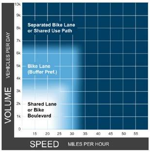
Designing for people of all ages and abilities requires physical separation at certain vehicle volumes (y-axis) and speeds (x-axis). The FHWA Bikeway Selection Guide provides general guidance for providing the appropriate facility based on the volume and speed of a road.
Notes:
1. Chart assumes operating speeds are similar to posted speeds. If they differ, use operating speed rather than posted speed.
2. Advisory bike lanes may be an option when traffic volume is <3K ADT.
Credit: Bikeway Selection Guide, FHWA, 2019

The bikeway facility selection chart below identifies appropriate shoulder widths for rural roads, designed to enhance safety and comfort for bicyclists across varying speeds and traffic volumes.
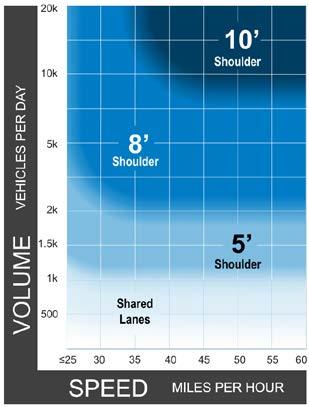
Notes:
1. This chart assumes the project involves reconstruction or retrofit in constrained conditions. For new construction, follow recommended shoulder widths in the AASHTO Green Book.
2. A separated shared use pathway is a suitable alternative to providing paved shoulders.
3. Chart assumes operating speeds are similar to posted speeds. If they differ, use operating speed rather than posted speed.
4. If the percentage of heavy vehicles is greater than 5%, consider providing a wider shoulder or separated pathway.

Page Intentionally Left Blank

Page Intentionally Left Blank

Bike facilities should provide a safe and comfortable experience that supports and encourages diverse users. This section provides guidance on the design of bike facilities for different contexts and roadway characteristics.
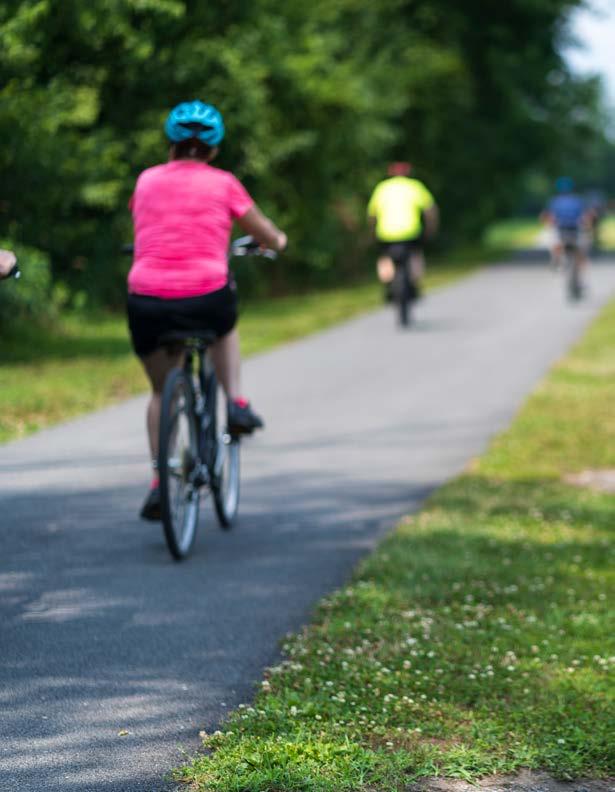
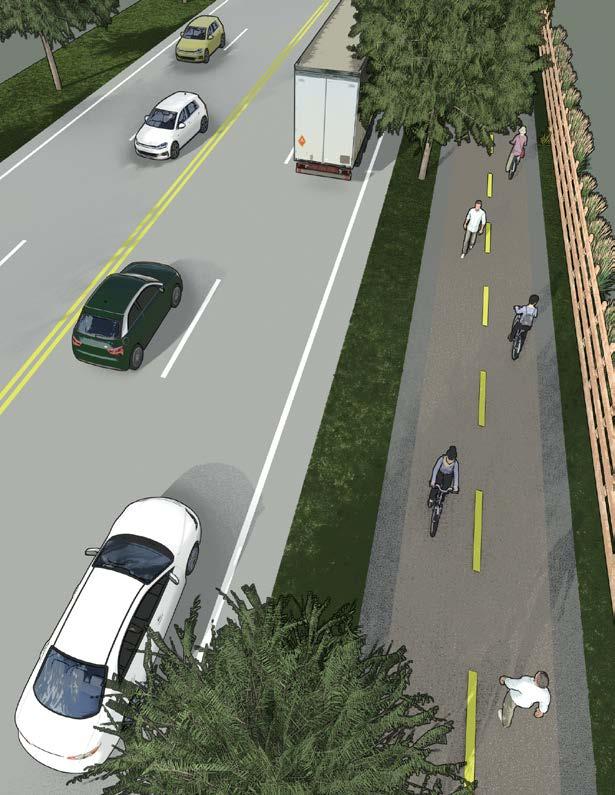
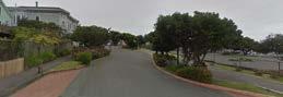
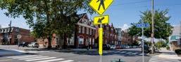
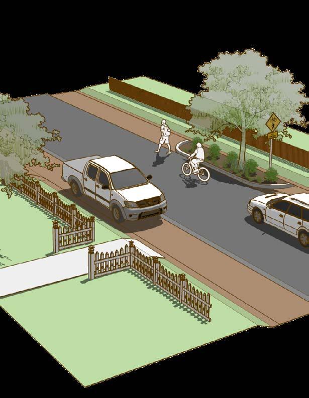
Shared use paths and sidepaths promote safe, accessible movement for nonmotorized users, including walkers, bikers, and sometimes equestrians. Both are bi-directional pathways designed to enhance connectivity and safety, but they differ in placement and context. They are particularly suited for roads with high traffic volumes and moderate to high vehicle speeds, offering physical separation from fast-moving vehicles to promote walking and biking.
Shared use paths are routes that may run entirely separate from roadways or adjacent to streets. Found in parks, greenbelts, or utility corridors, these paths provide network connections away from vehicular traffic. They can feature separated lanes for walking and biking or combine all modes into one space, with optional unpaved sections for equestrians. Sidepaths are a specific type of shared use path that runs parallel to and directly adjacent to roadways. Sidepaths often include vegetation to enhance aesthetics and safety, especially in rural settings, and require sufficient roadside space to ensure the path is safely outside the traveled roadway.
The following section summarizes general design guidance for shared use paths / sidepaths. Refer to the most recent MUTCD, AASHTO Guide for the Development of Bicycle Facilities, NACTO Urban Bikeway Design Guide, and FHWA Small Town and Rural Multimodal Networks for additional information as needed.
Preferred width should be determined based on context
Shared use paths should include a 2’ shoulder on either side and the edge of the path should be at least 5’ from the roadway.
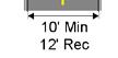
On 10- to 14- foot shared use paths, a centerline stripe may help clarify the direction of travel and organize traffic. On paths 15-foot or wider, separate walking and biking space may be designated.
Shared use paths may use materials such as asphalt or colored concrete to visually differentiate the space from a conventional sidewalk.
Shared use paths may be placed on both sides of the road where there are destinations on both sides of the road to increase access.
Short segments of sidepaths or shared use paths may be used to connect other bike facilities.
At intersections and crossings, detectable warning surfaces and curb ramps shall be installed.
At intersections and driveways, conflict striping should be considered to improve visibility for all users.
Shared use paths are best suited in areas where roadway crossings and driveways can be minimized or where overpasses and underpasses are feasible. Raised side street crossings should be installed at side streets and driveways, especially if the bikeway is at sidewalk level.
If drivers are anticipated to encroach on the shared use path, bollards or other preventative features may be placed at the entrance to the path. These should be highly visible, well lit, and designed for someone on using a wheelchair or riding a bike to pass through easily and, for people on bikes, without having to dismount.
If there is space to do so, it is ideal to include a detectable surface such as grass or a small curb where fully separated space is delineated for people walking and biking.
In general, where volumes of people walking and biking are anticipated to be higher, shared use paths should be designed to be wider. Constrained minimums should only be used for short stretches where every consideration has been taken to narrow other zones. The guidance below provides more information regarding preferred lane widths based on the speed and volume of expected user types:
(Standard) Shared Use Path
Shared Use Path
Volume Shared Use Path
Low Volumes, Heavy User Mix Shared Use Path
High Volume Shared Use Path
Source: FHWA Small Town and Rural Multimodal Networks
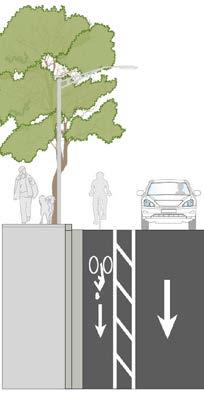
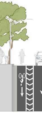
Roadway Separation
(plus an additional 2' for vertical elements)
(with a 3' clearance between trees and the pathway)
Source: FHWA Small Town and Rural Multimodal Networks
(plus an additional 2' for vertical elements)
(or vertical separator, or rumble strips)
For high-speed roads, a separation width of 16.5' to 20' is recommended to ensure safe positioning at crossings and intersections
Equestrian Use
In rural areas, the dimensions given for the urban and suburban context can be used. Additional rural guidance includes paths for equestrians. In areas where equestrian use is anticipated, provide a shared use path in addition to a natural surface path for equestrian use.
Equestrian Path
E-Bike users might ride at higher speeds on lower-volume paths and trails, which may result in conflicts with non-motorized bikes, pedestrians, or individuals in wheelchairs. Potential approaches to addressing this can include signs that implement e-bike speed limits or emphasize path etiquette such as safe speeds and non-motorized right of way.
Crossings are particularly important to consider for shared use paths as they are often the only location on the path where path users interact with vehicle drivers. The following crossing types should be considered when designing shared use paths:
At intersections, every effort should be made to maintain separation between people biking, walking, and driving. Potential intersection treatments which should regularly be considered include protected intersections, protected roundabouts, dedicated intersections, and two-stage left-turn queue boxes, among others.
When crossing side streets and higher volume driveways, raised side street crossings, slow turn wedges, and tight turn radii may be considered in addition to conflict markings to highlight the path crossing.
Shared use paths often cross mid block. In this case, Rectangular Rapid Flashing Beacons, Pedestrian Signals, or other signal treatments may be used in addition to advanced warning signs to prioritize path crossings.
Where geographically and financially feasible, shared use paths may cross over or under roads, freeways, railroad tracks, and other barriers. These crossing provide the highest level of comfort for users because they physically separate path users from other modes of traffic.
Employ small roadway corner radii to enforce turning speeds of 20 miles per hour or less. On highspeed roads, a deceleration lane may be necessary to achieve slower turning speeds.
For minor street crossings, sidepaths should have the same priority as the parallel roadway. To ensure clear sightlines for crossings, keep visual obstructions such as landscaping low. When connecting with on-street bikeways, it is essential to facilitate smooth transitions for path users when a sidepath ends. Use median islands and horizontal deflection of roadway travel lanes to slow vehicle traffic, improving crossing conditions for path users.
Center Line MarkingPassing Prohibited
The following standard markings may be utilized for lanes on shared use paths / sidepaths: Width to Match
Facility
Center Line MarkingPassing Permitted

shall be in center of opposing travel lanes and near crosswalks.
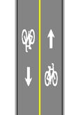
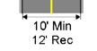
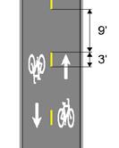
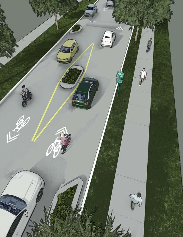
Where the path is 10-14’wide center line may be used to indicate directionality. A solid line indicates passing is not permitted and a dashed line indicates passing is permitted. Where paths are 15’ or wider and there is a desire to fully separate people walking and biking, a solid yellow line may be used to provide a 5’ minimum path for bidirectional travel and a 10’ minimum path for bidirectional path for bicyclist travel. Signage and bicycle and pedestrian markings may be painted on the path to intended users. When used in this way, it is optimal to provide a grass strip or other detectable surface to separate the paths of travel, resulting in a total width of more than 15 feet. For more information, see MUTCD Section 9E-13.
Dashed markings, also called “conflict markings” or “crossbikes”, may be used alone or in combination with green colored pavement to mark extensions of bike lanes through intersections, driveways, and other locations. These markings serve to increase awareness of where people biking may be positioned in the roadway and can help identify the path for people biking and guide them in movements which may be difficult to discern. For more information, see MUTCD Section 9E.03.
Green colored pavement may be used to enhance visibility of locations where people biking are expected to operate. Specifically, it may be used to enhance conflict markings, bike boxes, and other pavement markings. Green pavement shall not be used in place of dotted lines. For more information, see MUTCD Section 3H.06.
The following types of signage are commonly utilized in the design of shared use paths / sidepaths:
Where Paths Narrow
Consider using “Path Narrows” (MUTCD W5-4a) to indicate to people on the path where the path narrows, especially when the path is being narrowed to a constrained minimum.

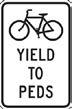
Indicating User Priority
“Bicycles Yield to Pedestrians” (MUTCD R9-6) may be used to indicate pedestrian priority.
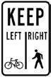
Indicating Directionality
“Keep Left | Right” (MUTCD R9-7) may be used to indicate which side of the path people walking and biking should stay on.
Indicating Directionality
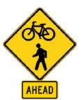
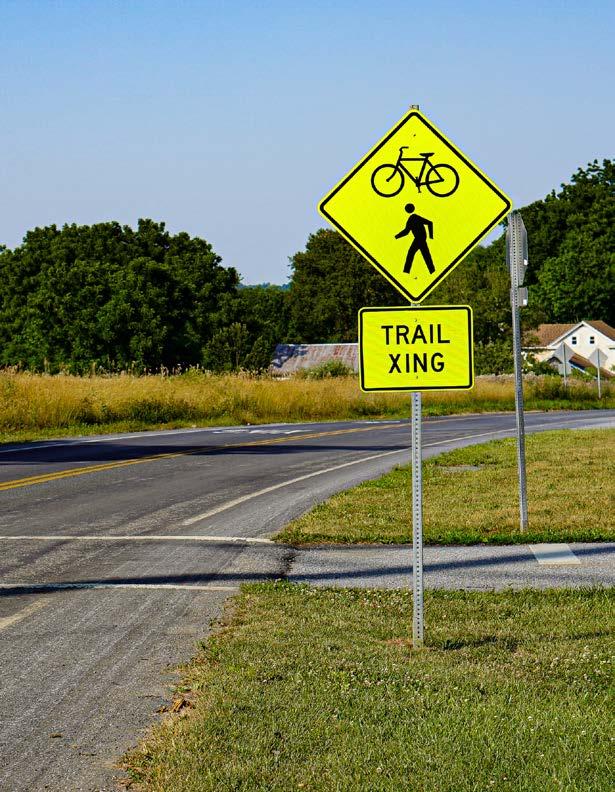
“Trail X-Ing” (MUTCD W11-15 and W11-15P) may be used to alert drivers to a shared use path crossing, especially when the path crossing is located midblock.
Shared use paths are considered pedestrian routes of travel and should be designed to meet all ADA requirements. Some of these include:
Cross Slopes and Grade
ADA requires cross slows for share use paths to be designed at 1.5 percent or less, and transitions should be a minimum of 5 feet for each one percentage change. Grade should not exceed five percent; if it must exceed five percent, handrails must be provided.
Crossings
Detectable warning surfaces and, where the path crosses at street grade, curb ramps should be provided at all crossings. Additionally, accessible pedestrian signals should be present.
Most shared use paths allow for mixed pedestrian and bicycle travel. Where the paths of travel are separated, a 2’ landscape or hardscape strip is preferred, but in more constrained areas a vertical element, grooved strip, pavement change, or other detectable edge.
Drainage should be considered in the design of shared use paths. Cross slopes and grades should facilitate drainage of water off of the path, and stormwater management treatments should be installed in the buffer between a path and the road where feasible.
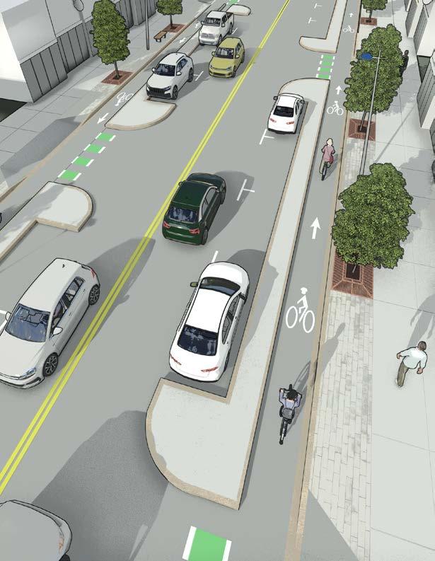
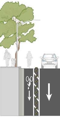
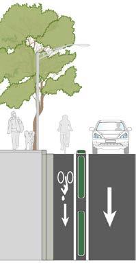
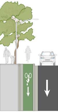
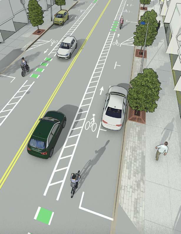
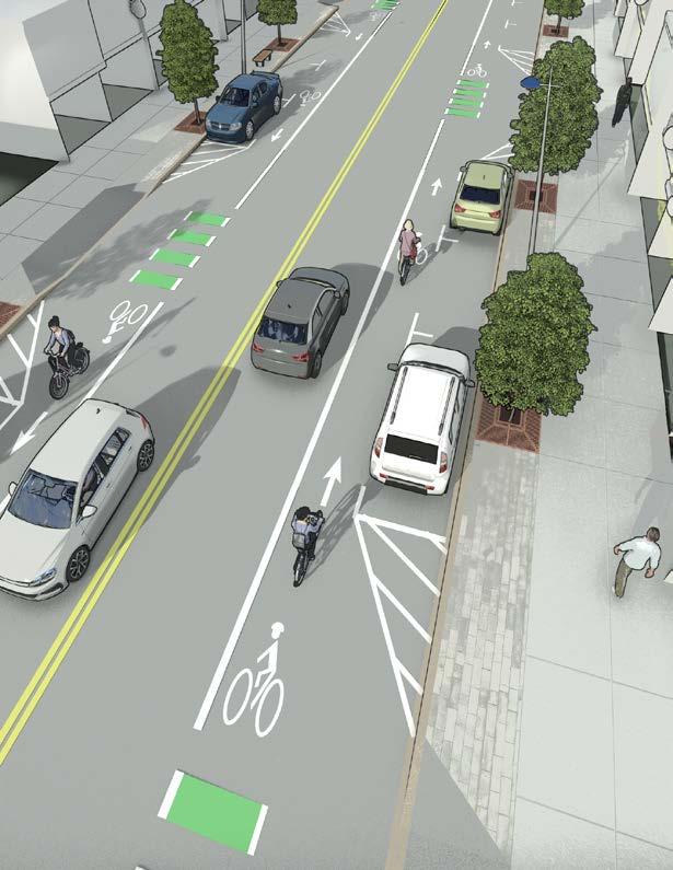
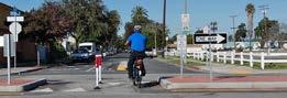
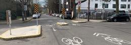
Protected bike lanes, also known as cycle tracks and separated bikeways, are fully separated designated for the use of people biking. They incorporate physical, vertical separation from motorized traffic, parking lanes, and adjacent walking facilities. Physical separation varies and includes flexible post delineators, raised medians, landscaping, or another physical object. This vertical element differentiates protected bike lanes from striped and buffered bike lanes. Streets with protected bike lanes should also have sidewalks on both sides to accommodate people walking. Protected bike lanes can accommodate one-way or two-way travel, on one or both sides of the street, and at street level, sidewalk level, or somewhere in between.
The following section summarizes general design guidance for protected bike lanes. Refer to the most recent MUTCD, AASHTO Guide for the Development of Bicycle Facilities, NACTO Urban Bikeway Design Guide, and FHWA Small Town and Rural Multimodal Networks for additional information as needed.
Bicycle lane word, symbol, and/or arrow markings shall be placed at the beginning of the protected bike lane and along periodic intervals based on engineering judgement.
Preferred bike lane width is determined based on facility type and context
Physical separation, which may or may not include painted markings, shall be used.
At intersections and crossings, detectable warning surfaces and curb ramps shall be installed.
At intersections and driveways, conflict striping should be considered to improve visibility for all users. Raised side street crossings may be installed at side streets and driveways, especially if the bikeway is at sidewalk level.
Manholes, drainage grates, or other obstacles should be set flush with the paved roadway and grates should be positioned perpendicular to the path of travel so as not to trap bike tires.
A curb, detectable edge, or other feature shall be used to provide visual and physical queues to separate the bikeway and walkway.
If the bike lane is parking protected, additional vertical elements should be considered between the parking lane and the bike lane. The buffer shall be at least 3’ when parking is present.
If parking is provided, accessible parking shall also be provided. The bikeway may be narrowed to accommodate the required path of travel, and curb ramps should be installed to provide access to the sidewalk.
Where parking protected bike lanes are installed, the curb may be painted red and a colored stripe may be painted in the parking space to indicate parking restrictions similar to what would be painted on the curb (white, green, yellow, or blue curb).
At bus stops, a bus island should be considered. People biking should yield to people walking at these points.
Yield markings and/or raised crossings may be installed where people walking are anticipated to cross the bikeway. Additionally, any space where people are anticipated to walk should be designed to meet ADA cross slope standards.
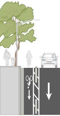
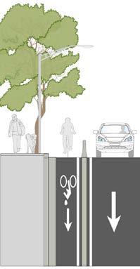
Vertical separation between the bikeway and vehicle lanes is one of the most important design elements to consider when designing a protected bike lane. There are a variety of potential options which can be used to separate bike lanes from vehicular traffic. Many factors influence the design decisions for these buffers, including number of driving lanes, vehicular speeds and volumes, drainage, driveways, available right-of-way, maintenance, aesthetics, durability, cost, and longterm maintenance.
This document does not include an exhaustive list of types of separation and is designed to allow flexibility to identify and implement new forms of separation as technology evolves. The table below provides a summary of some considerations for forms of separation. Each form is described in more detail on the following pages.
Performance
High = Relatively High
Med = Relatively
Moderate
Low = Relatively Low
3' Min 8' Min
• Parked vehicles are used to Provide visual and physical separation.
• Only effective on its own when parking is fully or almost fully occupied. Otherwise, additional vertical elements may be considered to provide separation.
• A minimum 3' buffer is required to provide space for the opening of car doors.
• If used, additional vertical elements should take into account the need for the opening of car doors.

28" - 36" Height
6' - 10' spacing (typical)
1.5' Min
• Hard but bendable posts.
• Closer spacing and/or additional vertical elements should be used if there are concerns about drivers parking in the bikeway.
• Relatively inexpensive to install,
• May require frequent maintenance.
• May be used for permanent installations
• Easy to modify and allow flexibility for design changes over time.
- 36"
- 36"
Min
6' - 10' spacing (typical) 8' spacing (typical) 40"
Min
• Operate similar to flexible posts, but are sturdier and higher cost.
• Generally considered more attractive than flexible posts.
• As with flexible posts, closer spacing and/or additional vertical elements should be used if there are concerns about drivers parking in the bikeway.
• Resembles a curb stop with a flexible post mounted on top of it.
• Combination of vertical and horizontal features provides a greater level of comfort for people walking and biking, and also discourages drivers from driving into the bike lane.
• While more expensive than a standard flexible post, this treatment is still relatively inexpensive and can be modified more easily than a curb.
• Small, oblong objects which are generally painted with yellow or white stripes to increase visibility.
• Due to low profile, provide less visual separation. May be used in combination with taller vertical elements to increase visibility.
• May pose a tripping hazard if used next to a parking lane.
• Low cost and easy to modify over time.
• Inexpensive, low linear barrier
• High level of durability
• Provides near-continuous separation
• As with Armadillos, the low profile limits visual separation and so these treatments may be used in combination with taller vertical elements to increase visibility.
• Wider buffers may be preferred with this treatment to offset the lower level of visual separation from vehicles.
30" Height (not including plant)
36" - 42"
Maintain consistent spacing
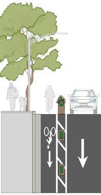
4' Min
• Provides a strong visual and physical barrier between people biking and drivers.
• Offers an opportunity for placemaking and beautification.
• May be placed closer together to provide a consistent barrier.
• Generally considered an expensive treatment to install and may require significant maintenance.
• Require a wider buffer space given their width and height.
• Most appropriate on streets with lower speeds and volumes.
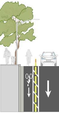
3' Min
4' Height Continuous spacing
• Lower cost treatment which provides continuous vertical separation.
• Highly durable treatment appropriate on roads with high vehicular speeds and volumes.
• May be painted to improve visual appeal.
• Not compatible with on street parking.
• Crash cushion may be needed at barrier ends.
• May have drainage impacts.
20' - 40' (typical)
6' spacing for drainage (typical)
2' Min, 3' where Parking, 4'+ Preferred
2' Min, 3' where Parking, 4'+ Preferred 6" Height
• Concrete curbs which are cast in place or precast.
• More expensive to construct but lower maintenance needs.
• Provide a high level of separation.
• Wider medians may provide space for landscaping, stormwater treatments, and other placemaking elements.
• May be mountable where emergency access is required.
• Gaps should be placed between medians to maintain drainage.
1' Min with Detectable Edge
• Provides a high level of comfort.
• Expensive to construct, but lower maintenance needs.
• A minimum 1' detectable edge, such as a grass strip or textured pavement, should be installed to provide visual and tactile delineation between the sidewalk and the bikeway.
• In constrained situations, different pavement types and markings may be used to provide separation between the sidewalk and bikeway.
The guidance for lane withs for protected bike lanes varies based on whether they are one- or twoway facilities and if they are at street or sidewalk level, or at an intermediate grade between the roadway and sidewalk. The bike lane should be buffered from adjacent street lanes (street buffer) and sidewalks (sidewalk buffer). Constrained minimums should only be used for short stretches where every consideration has been taken to narrow other zones. The guidance below provides more information regarding preferred lane widths based on national best practices.
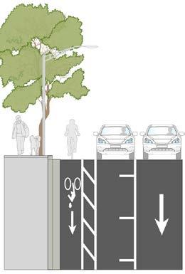
Delineator-Protected Bike Lanes
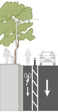
Curb-Protected Bike Lanes
Raised-Protected Bike Lanes
One-Way Separated Bike Lane
Two-Way Separated Bike Lane
Roadway Separation
Source: FHWA Small Town and Rural Multimodal Networks
Raised-Protected Bike Lanes
To prevent pedestrian encroachment, separated bike lanes next to sidewalks should be clearly distinguished. Use curbs, buffer spaces, different pavement materials, or tactile strips for separation.
Crossings are particularly important to consider for protected bike lanes, as they are where people biking face the highest level of interaction with vehicles. The following crossing types should be considered when designing protected bike lanes, and are discussed in further detail in the linked chapters.
At intersections, every effort should be made to maintain separation between people biking, walking, and driving. Potential intersection treatments which should regularly be considered include protected intersections, protected roundabouts, dedicated intersections, and two-stage left-turn queue boxes, among others.
When crossing side streets and higher volume driveways, raised side street crossings, slow turn wedges, and tight turn radii may be considered in addition to conflict markings to highlight the presence of people biking.
The following standard markings may be utilized for bike lanes:
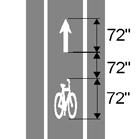
Bike symbols with directional arrows shall be used to help to alert road users that the protected bike lane is intended for use by people biking. They should be placed regularly within the bikeway and after signalized intersections. Where bike detectors are used, a bike detector marking may be placed to indicate the optional placement for a person biking to actuate a signal Additional signage and markings, including WAIT HERE FOR GREEN text, may be used to supplement the markings. For more information on symbols and markings, see MUTCD Figure 9E-1 and Section 9E-15.
Center Line MarkingPassing Prohibited
Center Line MarkingPassing Permitted
On two-way protected bike lanes, a center line may be used to indicate directionality. A solid line indicates passing is not permitted and a dashed line indicates passing is permitted. For more information, see MUTCD Section 9E-13.
Dashed markings, also called “conflict markings” or “crossbikes”, may be used alone or in combination with green colored pavement to mark extensions of bike lanes through intersections, driveways, and other locations. These markings serve to increase awareness of where people biking may be positioned in the roadway and can help identify the path for people biking and guide them in movements which may be difficult to discern. For more information, see MUTCD Section 9E.03.
Green colored pavement may be used to enhance visibility of locations where people biking are expected to operate. Specifically, it may be used to enhance conflict markings, bike boxes, and other pavement markings. Green pavement shall not be used in place of dotted lines. For more information, see MUTCD Section 3H.06.
The following types of signage are commonly utilized in the design of protected bike lanes.

“Bike Lane” (MUTCD R3-17) can be used to indicate to drivers they are not allowed to drive in the bike lane. Additionally, “No Parking Bike Lane” (R7-9 or 9a) signs should be installed and the curb should be painted red to dissuade drivers from parking in bike lanes and allow proper enforcement.
Where desired, “Bicycles Yield to Pedestrians” (MUTCD R9-6) may be used to indicate pedestrian priority at crossings.
Where wrong-way bike riding is present or anticipated, “Bicycle Wrong Way” (MUTCD R5-1b) and “Ride with Traffic” (MUTCD R9-3cP) signs may be utilized to discourage wrong-way riding.
When designing protected bikeways, it is important to consider the needs of people with disabilities. Protected bike lane design is evolving, and at the time this document was written, there is little formal federal guidance on accessible design for protected bike lanes. At a minimum, the following elements should be considered:
If a protected bikeway is designed at sidewalk level, a detectable edge should be included between the walking and biking travelways. Where possible, a 2’ minimum landscape or hardscape strip is preferred, but in more constrained areas a vertical element, grooved strip, or pavement change may be appropriate. For more information on detectable edge treatments, please see the FHWA Separated Bikeway Planning and Design Guide.
Detectable warning surfaces should be utilized to clearly define where pedestrians will cross the bikeway. People biking should yield to people walking across the crosswalk, and additional signage, rumble strips, yield markings, or stop bars can be utilized to alert people biking to the presence of the crossing. Additionally, accessible pedestrian signals should be present.
When design adjacent to on street parking or when heavy paratransit loading and unloading activity is expected, the bikeway design should be modified to allow for access for people with disabilities.
There are no formal requirements for cross-slopes on protected bike lanes. However, as cross slopes increase, it becomes more difficult for people utilizing adaptive bicycles and other assistive devices to navigate the bikeway. Therefore, cross slopes should be limited as much as possible. Where people are expected to walk across the bikeway or buffer area, like at accessible parking spaces, the space should be designed to meet ADA cross slope standards.
Protected bike lanes may impact existing drainage, depending on how they are designed. For street level protected bike lanes, this may be addressed by providing regular gaps in the raised barrier to allow water to flow into existing drainage inlets. When the curb is being modified, a drainage study may be conducted to determine if additional drainage treatments are needed.

Page Intentionally Left Blank
Buffered bike lanes provide additional horizontal separation between the bike and travel or parking lanes, increasing comfort and separation for people biking. Buffered bike lanes are preferred along streets with higher volumes and speeds, where conventional bike lanes may not adequately enhance comfort and safety for people biking. Buffers provide a greater space for bicycling without making the bike lane appear overly wide; overly wide space may attract unintended motor vehicle use for driving or parking.
The following section summarizes general design guidance for buffered bike lanes. Refer to the most recent MUTCD, AASHTO Guide for the Development of Bicycle Facilities, NACTO Urban Bikeway Design Guide, and FHWA Small Town and Rural Multimodal Networks for additional information as needed.
Bicycle lane word, symbol, and/or arrow markings shall be placed at the beginning of the bike lane and along periodic intervals based on engineering judgement.
Preferred bike lane width is determined based on facility type and context.
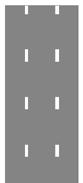
The buffer shall be marked with two solid white lines and hatching as shown in Buffer Markings. Buffers wider than 2’ require cross hatching at 10’ to 40’ spacing. 2-foot or narrower buffers do not require cross hatching. Preferred buffer width is determined based on context.
If the bike lane is adjacent to on-street parking, the bikeway may be placed between the curb and the parking lane. Consider making bike lanes as wide as possible to allow people biking to avoid the door zone. Where this is infeasible, the bike lane may be placed between the parking lane and vehicle lane. In this case, buffers should be placed on both sides of the bike lane as defined in Preferred Dimensions. If there is not space for a buffer on both sides of the bike lane and the bike lane must be placed between the parking lane and driving lane, the buffer may be placed only on one side. The determination of which side should be made based on engineering judgment, considering parking turnover and vehicle speed and volume.
The curb should be painted red where parking is not allowed. No parking signs (MUTCD R8-3) may be used to discourage parking in the bike lane.
At intersections and crossings, detectable warning surfaces and curb ramps shall be installed.
At intersections and driveways, conflict striping may be considered to improve visibility for all users.
Manholes, drainage grates, or other obstacles should be set flush with the paved roadway and grates should be positioned perpendicular to the path of travel so as not to trap bike tires.
The buffer shall be at least 3’ when parking is present.
At bus stops, a bus island should be considered. People biking should yield to people walking at these points. If there is not space for a bus island, the bus may pull out to the curb and share the space with people biking.
Yield markings and/or raised crossings may be installed where people walking are anticipated to cross the bikeway to further indicate priority users.
Where drivers are observed parking or driving in a bike lane, protected bike lanes should be considered.
The width of a bike lane significantly affects bicyclists' comfort and safety. Preferred widths accommodate most riders and support social riding. Wider lanes are ideal for areas with high traffic volumes, speeds, heavy vehicles, or frequent parking turnover. In constrained spaces, minimum dimensions may be used, but wider lanes with narrow buffers are generally preferable to provide more operating space. If wide buffers risk misuse by parked cars, vertical elements can prevent this. Gutters are excluded from bike lane widths. Design and street context should guide lane width decisions
Urban and Suburban Context
Buffered Bike Lanes (unprotected)
Buffer Width (No Parking)
Buffer
Rural Context
(Adjacent to Parking)
Source: FHWA Small Town and Rural Multimodal Networks
In order to be comfortable for most people, additional treatments may be considered to extend bike lanes to or through intersections, driveways, and other crossings, as follows:
At intersections, bike lane stripes may be dashed for merging. Common treatments include through lanes, bend outs, protected intersections, roundabouts, hardened centerlines, bike boxes, and twostage turn boxes.
When crossing side streets and higher volume driveways, slow turn wedges and tight turn radii may be utilized in addition to conflict markings to highlight the presence of people biking.
Markings
The following standard markings may be utilized for bike lanes: Directional and Placement Symbols

Width as Described Above
Bike symbols with directional arrows help to alert road users that the buffered bike lane is intended for use by people biking. They should be placed regularly within the bikeway and after signalized intersections. Where bike detectors are used, a bike detector marking may be placed to indicate the optional placement for a person biking to actuate a signal. Additional signage and markings, including WAIT HERE FOR GREEN text, may be used to supplement the markings. For more information on symbols and markings, see MUTCD Figure 9E-1 and Section 9E-15.
• Very low cost, paint-only solution.
• Easy to maintain and fits all sizes of maintenance vehicles / street sweepers.
• Only appropriate on streets with lower speeds and volumes.
• Diagonal hatching should used in the buffer area if the buffer is wider than 4'.
• Chevron hatching should be used in the buffer area is wider than 4'.
• It is preferable to create a wider bike lane with a narrow buffer as opposed to a standard bike lane with a wide buffer to allow people biking more space to operate.
• If the buffer is too wide, drivers may park in it. If this behavior is expected, additional vertical elements should be placed in the buffer zone to prevent it.
When contraflow buffered bike lanes are desired on one way roads, the contraflow bike lane should be placed on the left side of the road, so that people biking against traffic have vehicles to their left and the curb to their right. The buffer markings should be yellow to divide the bikeway from opposing traffic in addition to standard directional and placement symbols.
Dashed markings, also called “conflict markings” or “crossbikes”, may be used alone or in combination with green colored pavement to mark extensions of bike lanes through intersections, driveways, and other locations. These markings serve to increase awareness of where people biking may be positioned in the roadway and can help identify the path for people biking and guide them in movements which may be difficult to discern. For more information, see MUTCD Section 9E.03.
Where contraflow bike lanes are present, paint conflict / crossbike markings at driveways and intersections to highlight the potential for bike traffic.
Green colored pavement may be used to enhance visibility of locations where people biking are expected to operate. Specifically, it may be used to enhance conflict markings, bike boxes, and other pavement markings. Green pavement shall not be used in place of dotted lines. For more information, see MUTCD Section 3H.06.
Where contraflow bike lanes are present, consider utilizing colored pavement to draw attention to the contraflow facility.
The following types of signage are commonly utilized in the design of buffered bike lanes.
“Bike Lane” (MUTCD R3-17) signs should be used to distinguish the bike lane from the vehicle lane. Additionally, “No Parking Bike Lane” (R7-9 or 9a) signs should be installed and the curb should be painted red to dissuade drivers from parking in bike lanes and allow proper enforcement.
Where wrong-way bike riding is present or anticipated, “Bicycle Wrong Way” (MUTCD R5-1b) and “Ride with Traffic” (MUTCD R9-3cP) signs may be utilized to discourage wrong-way riding. For contraflow buffered bike lanes, additional signage may include:
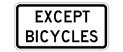
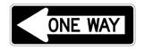
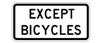
• “One Way” sign (MUTCD R6-1 or 2) with “Except Bicycles” plaque (MUTCD R3-7bP) at intersecting streets, alleys, and driveways.
• “Do not Enter” sign (MUTCD R5-1) with “Except Bicycles” (MUTCD R3-7bP)
Streets with bike lanes should include sidewalks with curb ramps which meet ADA standards. Additional considerations include:
Detectable warning surfaces should be utilized to clearly define where pedestrians will cross the bikeway. People biking should yield to people walking across the crosswalk, and additional signage, rumble strips, yield markings, or stop bars can be utilized to alert people biking to the presence of the crossing. Additionally, accessible pedestrian signals should be present.
Where designed next to on street parking, accessible parking spaces shall be included per ADA guidance. Where no parking is included, conflict markings may be used at locations where loading and unloading of paratransit vehicles is anticipated.
There are no formal requirements for cross-slopes on bike lanes. However, as cross slopes increase, it becomes more difficult for people utilizing adaptive bicycles and other assistive devices to navigate the bikeway. Therefore, cross slopes should be limited as much as possible.
Bike lanes typically do not impact drainage, however the installation of bike lanes may include additional treatments to support stormwater management.
Striped bike lanes designate exclusive space for people biking through the use of pavement markings and are typically appropriate on streets with speeds of 30 MPH or less. Bike lanes are intended for one-way travel and are typically provided on both sides of two-way streets, and on one side of one-way streets. Conventional bike lanes may vary in width. In some cases, contraflow bike lanes may be provided to support access on one-way streets. Bike lanes are typically on the right side of the street, between the outside travel lane and curb, parking lane, or road edge. While the bike lane distinguishes predictable areas for bicyclist and automobile movement, bicyclists may leave the bikeway to pass other bicyclists or avoid debris and other traffic conflicts.
A climbing bike lane (also known as a climbing lane) is a type of bike lane that parallels a vehicle travel lane going uphill to provide a space for slower-moving bicyclists; a climbing bike lane in the uphill direction can be paired with a bike route in the downhill direction in instances where there is insufficient space for bike lanes in both directions.
The following section summarizes general design guidance for bike lanes. Refer to the most recent MUTCD, AASHTO Guide for the Development of Bicycle Facilities, NACTO Urban Bikeway Design Guide, and FHWA Small Town and Rural Multimodal Networks for additional information as needed.
Bicycle lane word, symbol, and/or arrow markings shall be placed at the beginning of the bike lane and along periodic intervals based on engineering judgement.
A solid 6-inch wide white lane line shall be used to identify the edge of the bike lane.
Preferred bike lane width is determined based on facility type and context
The curb should be painted red where parking is not allowed. No parking signs (MUTCD R8-3) may be used to discourage parking in the bike lane.
If the bike lane is adjacent to on-street parking, the bikeway should be placed between the travel lane and on street parking. If there is space to provide a 3’ buffer between the bikeway and parking lane while maintaining the minimum recommended bikeway width, the bikeway should be placed between the curb and the parking lane. Consider making bike lanes as wide as possible to allow people biking to avoid the door zone.
At intersections and crossings, detectable warning surfaces and curb ramps shall be installed.
At intersections and driveways, conflict striping may be considered to improve visibility for all users.
Manholes, drainage grates, or other obstacles should be set flush with the paved roadway and grates should be positioned perpendicular to the path of travel so as not to trap bike tires.
At bus stops, a bus island should be considered. People biking should yield to people walking at these points. If there is not space for a bus island, the bus may pull out to the curb and share the space with people biking.
Yield markings and/or raised crossings may be installed where people walking are anticipated to cross the bikeway to further indicate priority users.
Where drivers are observed parking or driving in a bike lane, protected bike lanes should be considered.
The width of a bike lane has a significant impact on a bicyclists’ comfort and their central operating position within a bike lane. Preferred widths are likely to be comfortable to most people, and wider bike lanes can allow for social riding (two people riding side by side). Use minimum dimensions only in constrained situations. Wider bike lanes are preferred in environments with higher traffic volumes, higher traffic speeds, corridors with a high percentage of heavy vehicles, and where adjacent parking utilization and/or turnover is high. If a gutter plan is present, it is not included as part of the bike lane. The guidance below provides more information regarding preferred lane widths based on the design and street context.
Adjacent to parking lane (without buffer)
- 8'
Adjacent to edge of pavement or gutter pan 6' - 8'
(7' or greater configure with a buffer zone to discourage vehicle use)
Source: FHWA Small Town and Rural Multimodal Networks
4' when no curb and gutter is present
5' when adjacent to curb face, guardrail, onstreet parking, or other vertical surface
In order to be comfortable for most people, additional treatments may be considered to extend bike lanes to or through intersections, driveways, and other crossings, as follows:
At intersections, the bike lane stripe may be dashed where drivers merge across the bikeway. Other potential intersection treatments which might regularly be considered for bike lanes include through bike lanes, bend outs, protected intersections, protected roundabouts, dedicated intersections, hardened centerlines, bike boxes, and two-stage left-turn queue boxes, among others.
When crossing side streets and higher volume driveways, slow turn wedges and tight turn radii may be utilized in addition to conflict markings to highlight the presence of people biking.
The following standard markings may be utilized for striped bike lanes:
Width as Described Above
Standard Crossbike Marking Chevron Crossbike Marking
Width to Match Bicycle Facility
Directional and Placement Symbols
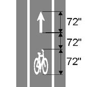
Bike symbols with directional arrows help to alert road users that the bike lane is intended for use by people biking. They should be placed regularly within the bikeway and after signalized intersections. Where bike detectors are used, a bike detector marking may be placed to indicate the optional placement for a person biking to actuate a signal. Additional signage and markings, including WAIT HERE FOR GREEN text, may be used to supplement the markings. For more information on symbols and markings, see MUTCD Figure 9E-1 and Section 9E-15.
Placement shall be in center of opposing travel lanes and near crosswalks.
Conflict / Crossbike Markings
Dashed markings, also called “conflict markings” or “crossbikes”, may be used alone or in combination with green colored pavement to mark extensions of bike lanes through intersections, driveways, and other locations. These markings serve to increase awareness of where people biking may be positioned in the roadway and can help identify the path for people biking and guide them in movements which may be difficult to discern. For more information, see MUTCD Section 9E.03.
Where contraflow bike lanes are present, paint conflict / crossbike markings at driveways and intersections to highlight the potential for bike traffic.
Green colored pavement may be used to enhance visibility of locations where people biking are expected to operate. Specifically, it may be used to enhance conflict markings, bike boxes, and other pavement markings. Green pavement shall not be used in place of dotted lines. For more information, see MUTCD Section 3H.06.
Where contraflow bike lanes are present, consider utilizing colored pavement to draw attention to the contraflow facility.
The following types of signage are commonly utilized in the design of striped bike lanes:
Where contraflow bike lanes are present, the following signs should be used:
• “One Way” sign (MUTCD R6-1 or 2) with “Except Bicycles” plaque (MUTCD R3-7bP) at intersecting streets, alleys, and driveways.
• “Do not Enter” sign (MUTCD R5-1) with “Except Bicycles” (MUTCD R3-7bP)
“Bike Lane” (MUTCD R3-17) signs should be used to distinguish the bike lane from the vehicle lane. Additionally, “No Parking Bike Lane” (R7-9 or 9a) signs should be installed and the curb should be painted red to dissuade drivers from parking in bike lanes and allow proper enforcement.
Streets with bike lanes should include sidewalks with curb ramps which meet ADA standards. Additional considerations include:
Detectable warning surfaces should be utilized to clearly define where pedestrians will cross the bikeway. People biking should yield to people walking across the crosswalk, and additional signage, rumble strips, yield markings, or stop bars can be utilized to alert people biking to the presence of the crossing. Additionally, accessible pedestrian signals should be present.
Where designed next to on street parking, accessible parking spaces shall be included per ADA guidance. Where no parking is included, conflict markings may be used at locations where loading and unloading of paratransit vehicles is anticipated.
There are no formal requirements for cross-slopes on bike lanes. However, as cross slopes increase, it becomes more difficult for people utilizing adaptive bicycles and other assistive devices to navigate the bikeway. Therefore, cross slopes should be limited as much as possible.
Bike lanes typically do not impact drainage, however the installation of bike lanes may include additional treatments to support stormwater management.
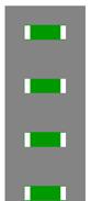
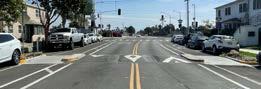
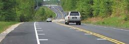
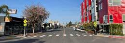
Paved shoulders are designed along the edges of roadways to create functional space for people walking and biking, especially when other separated facilities (e.g., dedicated bike lanes or sidewalks) are unavailable. These shoulders should include white striping to clearly define the visual separation from vehicle lanes. People bicycling are to travel in the same direction as the adjacent traffic lane. Paved shoulders are suitable for roads with moderate to high traffic volumes and speeds, including those with significant truck traffic. While paved shoulders can function on multilane roads with heavy traffic, they do not provide a low-stress experience for users.
The following section summarizes general design guidance for paved shoulders. Refer to the most recent FHWA Small Town and Rural Multimodal Networks for additional information as needed.
Longitudinal markings include white solid lines or buffer zones to enhance visual separation from vehicle traffic.
Colored or contrasting pavement can be used on the paved shoulder as an aesthetic treatment to improve the visual distinction between the shoulder and the roadway.
Edge line rumble strips, placed on the edge line or within a buffer, can help reduce roadway departure crashes and minimize conflicts with people biking.
The recommended minimum width for paved shoulders is dependent on roadway conditions. To safely accommodate bicyclists and pedestrians, a minimum width of 4 feet should be provided next to the road edge or curb, excluding any buffer or rumble strips. According to the AASHTO Bike Guide, the shoulder should be wider in areas where vehicle speeds exceed 50 miles per hour, where heavy trucks, buses, or recreational vehicles frequently travel, or where there are stationary obstructions along the right side of the road. When feasible, providing a wider shoulder enhances comfort, allows for passing, and supports side-by-side riding.
Source: FHWA Small Town and Rural Multimodal Networks
Source: FHWA Small Town and Rural Multimodal Networks
At intersections, the shoulder is often narrowed or replaced by turning lanes. While turning lanes may encroach on the shoulder, at least 6' of shoulder space should be preserved for bike travel, with an absolute minimum width of 4' to maintain accessibility for people biking. The shoulder should remain immediately to the right of right-turn lanes. For intersections with right-turn lanes, paved shoulders should be designated as bike lanes or separated bike lanes.
A right-turn lane should be added to the right of the bike lane, with dotted line extensions making the entrance to the turn lane. Signs informing drivers to yield to people biking should be included.
For greater comfort, the shoulder can transition into a one-way separated bike lane or shared-use path before the intersection, maintaining separation up to the crossing.
The edge of the paved shoulder should be clearly marked to prevent vehicle encroachment. Options for enhanced delineation beyond a standard white line includes:
• A wide 8" solid white line
• A narrow buffer with two 4" solid white lines separated by at least 18"
• A wider buffer with the same two 4" white lines and crosshatch markings within the buffer space
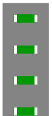
A bicycle gap pattern is required to allow people biking to enter and exit the shoulder safely. This pattern typically includes a 12-foot clear gap followed by rumble strips spaced 40 to 60 feet apart. To improve comfort for people biking, the following dimensions are recommended for rumble strips:
• 12" spacing center-to-center
• 6" - 8" long, perpendicular to roadway
• 6" wide, measured parallel to roadway
• 3/8" inch deep
Vehicular Travel Lane 12' min
Paved Shoulder
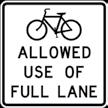
No signs are necessary on paved shoulders, but they can be used to designate a road as a bicycle route.
When paved shoulders are intended for pedestrians, they must meet ADA requirements.
Paved shoulders typically do not impact drainage, however installation may include additional treatments to support stormwater management.
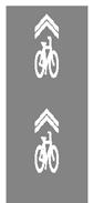
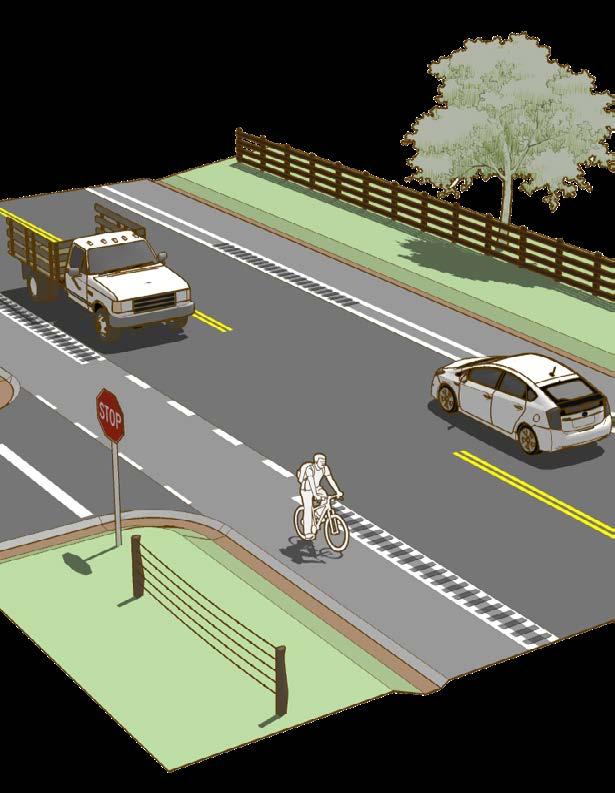
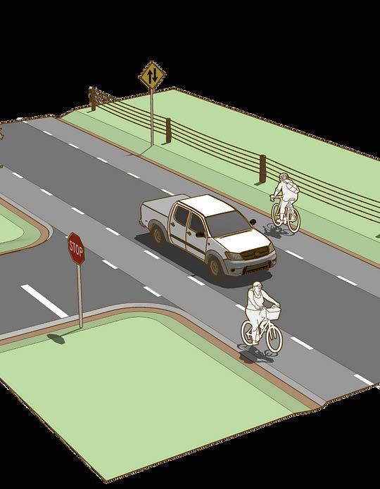
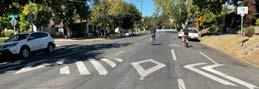
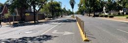
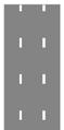
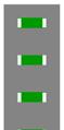
Advisory bike lanes, also called advisory shoulders or dashed bike lanes, create usable shoulders for people biking that requires little to no widening of the paved roadway surface. Advisory bike lanes features two dashed shoulders, one on each side of the road, and a shared two-way center lane for vehicle traffic. Vehicles may enter the advisory bike lanes only when necessary to pass, provided people biking are not present. Advisory bike lanes are preferred along streets with low traffic volumes and speeds, typically found in rural or small-town settings. Advisory bike lanes may be an option in urban or suburban contexts when traffic volume is less than 3,000 average daily traffic. The following section summarizes general design guidance for advisory bike lanes.
The following section summarizes general design guidance for advisory shoulders / bike lanes. Refer to the most recent FHWA Small Town and Rural Multimodal Networks for additional information as needed.
A broken lane line used to delineate the advisory bike lane.
Contrasting paving materials that visually differentiate the shoulder from the roadway and discourage vehicle encroachment.
Stripe a normal solid white edge line in addition to the broken advisory shoulder line.
Mark the roadway's center line with short sections of pavement marking to separate opposing traffic at key locations, such as curves, hills, bridge approaches, and at-grade crossings. In these areas, the paved roadway may be widened to accommodate advisory bike lanes.
The two-way center travel lane is created from the remaining paved roadway space after the advisory bike lane has been accounted for.
Source: FHWA Small Town and Rural Multimodal Networks
Interactions when vehicles are traveling in opposite directions meet by two-way center lane widths:
• Practical Minimum Width: 10' - Requires vehicles to encroach into the advisory shoulder when passing each other in opposite directions.
• Preferred Minimum Width: 13.5' - Two cars can pass at very low speeds within the center lane, but typically still encroach in the shoulder.
• Preferred Maximum Width: 16' - Allows two cars to pass at moderate speeds without needing to use the advisory shoulder.
• Absolute Maximum Width: 18' - Equivalent to two 9' lanes, reducing the need for encroachment into the shoulder.
Source: FHWA Small Town and Rural Multimodal
Advisory bike lane designs are most effective on roadway segments without frequent stop signs or signal-controlled intersections. The visual continuity of the advisory bike lane should be maintained across driveways and street crossings. At controlled intersections, a conventional shoulder should be provided, or the roadway should be designed for shared use. If contrasting pavement material is used, extend it through driveways and minor intersections.
At minor street crossings, use a dotted line extension on both sides of the advisory bike lane to maintain clear lane delineation.
At stop-controlled or signalized intersections, end the advisory bike lane at least 50 feet before the intersection.
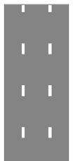
The following standard markings may be utilized for advisory bike lanes: Advisory Shoulder Striping
• A broken lane line used to delineate the advisory bike lane consisting of 3-foot line segments and 6-foot gaps.
• A normal solid white edge line may be used in addition to the broken advisory bike lane line for additional edge definition.
• Optionally, pavement color can be added to differentiate from the rest of the roadway.
Do not mark a center line on the roadway except for short sections at specific locations. Specifically, mark the roadway's center line with short sections of pavement marking to separate opposing traffic at key locations, such as curves, hills, bridge approaches, and at-grade crossings.
The following types of signage are commonly utilized in the design of advisory bike lanes:

Consider using an unmodified Two-Way Traffic warning sign to clarify two-way operation of the road.
Use a "No Center Line" warning sign to help clarify the unique striping pattern.
Use a "No Parking on Pavement" to discourage parking within the advisory bike lane.
Advisory shoulders / bike lanes are described here to not be used by people walking. When advisory shoulders are intended for pedestrians, they must meet ADA requirements.
Advisory bike lanes typically do not impact drainage.
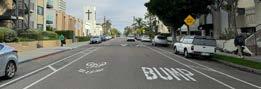
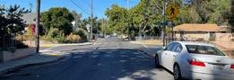
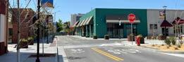
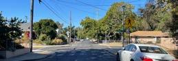
Bike boulevards, also known as bicycle boulevards, neighborhood greenways, or neighborhood bike routes, are typically traffic calmed residential streets with low vehicle volumes and low speeds where motor vehicles and bicycles share the road space. Bike boulevards use pavement markings, signs, and traffic calming elements to enhance safety and comfort for people on bicycles.
Many local streets in small towns or rural areas often have low-speed, low-traffic conditions that make them ideal for implementing bike boulevards. Bike boulevards are only appropriate on streets with low speeds (preferably 20-25 MPH) and vehicular volumes (preferably 3,000 vehicles per day or less). When speeds or traffic volumes exceed preferred levels, traffic calming techniques can be applied to improve conditions. Bike boulevards aim to optimize through-travel for people biking and include treatments to create low-stress crossings across busy streets. They should be designed to be as direct as possible and include connections to nearby destinations which limit out of direction travel.
The following section summarizes general design guidance for bike boulevards. Refer to the most recent MUTCD, AASHTO Guide for the Development of Bicycle Facilities, NACTO Urban Bikeway Design Guide, and FHWA Small Town and Rural Multimodal Networks for additional information as needed.
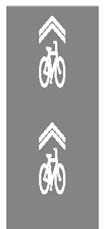
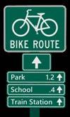
Bicycle wayfinding signage and pavement markings shall be included on bike boulevards. Pavement markings should be used to indicate preferred positioning in the road as well as wayfinding at turns.
Bicycle wayfinding signage should be placed anywhere there is a decision point or turn required. The signs should include destinations with arrows and distances.
The orientation of the chevron marking as part of the shared lane marking should indicate the appropriate direction of travel along the bike boulevard.
If on street parking is included, consider marking a 2’ to 3’ buffer between the travel lane and parking lane if the travel lanes are wider than 11’.
Confirmation signs may be included listing destinations and or distances in addition to standard directional wayfinding signage.
Traffic calming elements should be included at regular intervals (250-300’), both mid-block and at intersections.
Bike boulevards should have a design speed of 20 MPH, although posted speed may differ.
The curb should be painted red where parking is not allowed. No parking signs (MUTCD R8-3) may be used to discourage parking in the bike lane.
At intersections and crossings, detectable warning surfaces and curb ramps shall be installed.
At offset or complex intersections, shared lane markings may be painted through the intersection.
On one-way streets, a contraflow bike lane may be included to allow bicycle travel in the opposite direction of traffic.
Where there is additional space, bike boulevards may include striped bike lanes in addition to traffic calming.
On streets with a significant uphill grade, a climbing bike lane may be provided in the uphill direction.

Speed reduction measures on bike boulevards help maintain desired speeds. In lowerdensity areas, they focus on reducing speeds rather than traffic volume, with slow points spaced 300' - 400' apart to keep midpoint speeds around 25 MPH. Three categories of speed reduction measures are commonly applied.
• Physical Measures: Vertical deflections (e.g., speed humps), horizontal shifts, and roadway narrowing.
• Nonphysical Measures: Signs and markings to raise driver awareness.
• Diversion Treatments: Restrict certain traffic movements to limit cut-through traffic.
The following features outline potential options to achieve lower vehicle speeds and volumes, adaptable to the specific context and needs of each project.
Elevated 3-4" mounds placed in the roadway to slow vehicles. These may include gaps for emergency vehicles and bicycles to pass without horizontal deflection. They can be positioned near, but not within, intersections. Placing them on either side of a crosswalk creates a slow zone to reduce speeds and enhance comfort. Speed humps differ from speed tables mainly in length and profile.
Curb extensions or edge islands placed midblock to narrow the roadway over a short distance. They are typically applied midblock on low volume, low speed streets. If bike lanes are included, cut outs may be provided to allow people biking to pass through. In rural contexts, this design forces vehicles to merge into a single lane.
A street with curb extensions or other treatments to create a narrow or curved roadway, requiring people driving to slow down to navigate the curves. They are applied midblock, and may provide additional opportunities for landscaping, on-street parking, or other elements.

Short medians in the center of the street. Median islands require people driving to navigate around them, which helps to slow traffic. They can be applied at intersections of midblock. Median islands may include a cut out to provide protected space for people walking and biking when crossing the street.
Narrowing lanes to 10’ or less to reduce the total amount of space for vehicles, providing visual cues for drivers to slow down. This effect may be achieved via striping, adding a bikeway, adding vertical elements, or moving curb. This treatment may be applied midblock or at intersections on any street.
A circular intersection which is designed features such as an offset and medians to slow traffic entering and traveling through the intersection. As with traffic circles, incoming traffic yields to traffic in the roundabout and travels in a circle.
Changing roadway geometry or narrowing curb radii increases the amount of curb space, requiring vehicles to slow down when turning. Curb radii should be designed to induce a turning speed of 15 mph or less, although mountable curbs may be used to allow larger vehicles to pass. This treatment can also be used to realign skewed intersections to right angles.
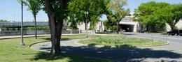
A circle placed in the middle of an intersection, requiring incoming traffic to yield to traffic in the intersection and travel in a circle around the median. Traffic circles generally include yield signs on the intersection approach.
Places where the intersection is elevated to the height of the sidewalk, which helps to slow drivers and improves the visibility of people who are walking across the street or who are waiting to cross. They can be applied at any intersection. A variation of raised intersections includes raised crosswalks, which only raise the crosswalk to the height of the sidewalk.
Vertical features (typical flexible delineators or other raised feature) installed at intersections to increase driver yielding to people in crossings by enforcing a wider turn angle. The method may include vertical elements and may be designed as mountable. 6-foot extensions are recommended but should be no less than 2 feet.
Barriers that partially or fully close the street to vehicular traffic while still allowing access for people walking and biking. There are many different ways diverters could be configured, and they can be designed to allow access for emergency vehicles, buses, or other service vehicles. For more information on traffic diverters.
Streets may be closed at intersections or mid-block to prevent through traffic. Street closures may be designed to allow emergency vehicles, people biking, and people walking to pass through, and may also be used to create an opportunity for placemaking like mini parks, landscape, or stormwater features.
Nonphysical speed reduction measures, such as signs and markings, are typically suited for higherspeed roads and transition areas from high to low speeds. These measures aim to warn, regulate, and influence driver behavior.
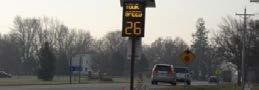
Inform drivers of their current speed and reminds them of the roadway's posted speed limit.
White, 1-foot rectangles along lane edges, spaced closer together, create the illusion of increased speed and narrower lanes.
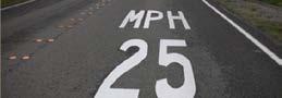
Reinforce posted speed limits for drivers.
Crossing enhancements can improve user comfort, increase gap opportunities for crossing, and increase the rate at which drivers yield to non-motorists. Key enhancements can include:
Pavement markings and signs increase driver awareness of crossing areas.
Rectangular rapid flashing beacons can be installed in locations with low driver compliance for yielding in order to supplement crossing signs and emphasize the need for drivers to yield.

In areas with multiple lanes, high-speed traffic, or no space for a median island, a full traffic signal or pedestrian hybrid beacon can help ensure safe crossings.
Reduce pedestrian exposure to traffic and increases visibility for those crossing. Curb extensions should be avoided in shoulder areas where they may interfere with bicycle traffic along main roadways.
Divide crossings into multiple stages, allowing people walking and biking to find gaps in traffic one direction at a time. For bicycle boulevards, median islands should be at least 8' deep to safely accommodate people biking.
The following standard markings may be utilized for bike boulevards:


Width to Match Bicycle Facility Placement shall be in center of opposing travel lanes and near crosswalks.
Width to Match Bicycle Facility
Shared lane marking with directional arrows help to alert road users that the buffered bike lane is intended for use by people biking. They should be placed regularly within the road, typically in the center of a lane, and after signalized intersections. For more information on symbols and markings, see MUTCD Figure 9E-1 and Section 9E-15.
At offset or complex intersections, directional sharrows may be painted through intersections to indicate the path of travel. Alternatively, Chevron Crossbike Markings or dashed markings, also called “conflict markings” or “crossbikes”, may be used alone or in combination with green colored pavement. These markings serve to increase awareness of where people biking may be positioned in the roadway and can help identify the path for people biking and guide them in movements which may be difficult to discern. For more information, see MUTCD Section 9E.03.
The following types of signage are commonly utilized in the design of bike boulevards.
MUTCD R9-20 signs indicate to drivers and people biking to expect people biking to position themselves anywhere within the lane that feels comfortable.
Two main types of wayfinding signage should be considered on bike boulevards: directional signs and confirmation signs. Directional signs should be placed at decision points, while confirmation signs can be placed at regular intervals along the bike boulevard to help riders know they are still on the right path. Both types of signs should include up to 3 destinations, directional arrows, and distance and/or time to destination. For more information on wayfinding signage, see MUTCD Section 9D.01
Bike boulevards should be designed to meet all ADA requirements for a standard street. Cross slopes should be limited as much as possible, as when cross slopes increase, it becomes more difficult for people utilizing adaptive bicycles and other assistive devices to navigate the bikeway. Therefore, cross slopes should be limited as much as possible.
Bike boulevards typically do not impact drainage, however the installation of traffic calming features may include additional treatments to support stormwater management.
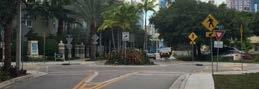
A Yield roadway is a shared space where people walking, biking, and driving coexist along a slowspeed, low -volume road. When traffic volumes and speeds are low, people walking and biking can comfortably use the roadway alongside vehicles. According to AASHTO, a very low-volume street is classified as a local road with fewer than 400 vehicles per day. To encourage slow vehicle speeds, these roads are typically designed to be narrow, less than 20' wide. This narrow two-way street accommodates bidirectional traffic without centerline markings. Yield roads are preferred on local rural streets, providing connections between residential neighborhoods and other key destinations. The following section summarizes general design guidance for yield roads.
The following section summarizes general design guidance for yield roadways. Refer to the most recent FHWA Small Town and Rural Multimodal Networks for additional information as needed.
A1
Roadside/parking/queuing to support on-street or shoulder parking for property access. When vehicles traveling in opposite directions meet, one may need to pull into a parking lane or driveway to allow the other to pass. The parking lane should be made from a contrasting material to distinguish it from the travel lane. Suitable materials include crushed stone, gravel, turf, or bituminous pavement.
B1
A wider, unpaved roadside area can accommodate a larger tree canopy. Trees can be planted at regular intervals along the roadside, helping to visually and physically narrow the corridor. This enhances the aesthetic appeal of the environment while also encouraging slower vehicle speeds.
The paved two-way travel lane should be designed to be narrow, promoting slower vehicle speeds and encouraging courtesy yielding when vehicles traveling in opposite directions meet.
• 16' to 18': Supports two-way traffic but requires vehicles to slow down to pass each other.
• 12' to 15': Too narrow for two vehicles to pass side-by-side; one vehicle may need to pull into a roadside or driveway. For lanes narrower than 15', include pull-out areas every 200' to 300'.
• Can be provided on the paved roadway or on earth shoulders.
• Use a contrasting material for the parking lane to distinguish it from the travel lane, doubling as pull-out areas when needed.
Source: FHWA Small Town and Rural Multimodal Networks
Source: FHWA Small Town and Rural Multimodal Networks
No special treatment is required at uncontrolled crossings. However, implementing parking prohibitions 20' to 50' before intersections can help accommodate large vehicle turning movements.
For two-way, single-lane roads, the stopping sight distance should be double of that of a comparable two-lane road to ensure adequate stopping time. This is especially important around curves and at uncontrolled intersections.
No markings are necessary for implementation. Centerlines should not be marked within the travel area.
The following types of signage are commonly utilized in the design of yield roadways:
Consider using a W11-1, W1-2, or W11-15 warning sign to inform road users that shared use by pedestrians and/or bicyclists might occur.
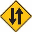
Consider using an unmodified Two-Way Traffic warning sign to clarify two-way operation of the road.
Yield roadways allow people walking, biking, and driving to share the same space. As it is intended to be used by people walking, the roadway must meet accessibility guidelines for walkways.
Limiting paved surfacing on the roadside encourages natural stormwater management with the use of gravel, turf, or earth.

Page Intentionally Left Blank

Page Intentionally Left Blank

Page Intentionally Left Blank

Intersection Typologies provide intersection design guidelines for the needs of people biking when they intersect. These guidelines are derived from consolidating best practices and recommendations from the FHWA MUTCD, NACTO Bike Design Guide, and other sources.
Furthermore, the Intersection Typologies offer an approach to determine which intersection treatments and solutions are most appropriate based on existing or planned bike facilities, as well as the project's goals and constraints. This process is designed to present a range of intersection treatments and solutions that can be used for intersection retrofits, new builds, or applied to whole intersections or specific legs of an intersection.
Intersections are critical points of conflict between different road users and represent a particularly challenging and potentially stressful place for people biking to navigate. For those "interested but concerned" in biking—or rather the majority of CYMPO residents—the presence of bike facilities alone may not be sufficient to encourage biking if intersections are not designed to be comfortable for people biking. These users are more likely to choose biking as a mode of transportation if they feel secure navigating intersections, which are frequently perceived as the most intimidating and hazardous parts of a journey. By ensuring that intersection designs address the specific needs and concerns of these riders, intersection typologies can help create a more comprehensive and inviting bike network, ultimately encouraging more people to choose biking as a viable and safe option.
1 Determine Bike Path Compatibility
2 Refine Options Considering Project Goals and Constraints STEP
3 Review Applicable Intersection Typologies and Review Design Details
Step 1 of the Intersection Typology process includes determining which types of bike facilities will be present or are planned for the intersection and selecting Intersection Typologies which are compatible with the bike facilities. In Step 2, consider the goals the project, such as costs, available right of way, among others. Each treatment is rated on a scale from Low to High regarding how well they meet each goal. Select one or more Intersection Typologies as potential candidates based on these ratings. In Step 3, review the selected Intersection Typologies. Each Intersection Typology has a 2-page spread with the elements below. Additional information regarding unique intersection types as well as intersection treatment, marking, and signage details are also provided in this chapter to support the design process.
Formal guidance documents for nationally accepted standards which should be referenced when designing the intersections
Optional intersection elements that may be used but can be removed from the design if they are determined infeasible or unnecessary in the design process, with hyperlinks to pages with further detailed guidance
Recommended intersection elements that are should always be considered for the intersection, with hyperlinks to pages with further detailed guidance
A brief description of the solution and general application considerations
Icons indicating which bike facilities are compatible with the design recommendations
Intersection design detail including dimensions and callouts for recommended and optional intersection elements
Identify intersection types which are compatible with the bike facility.
NOTE: In some cases, different legs of the intersection may have different solutions.
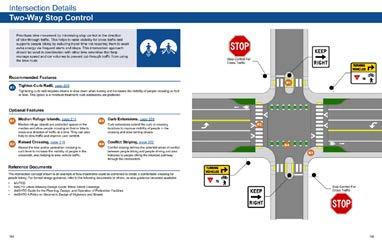
Two-Way Stop Control
Raised Intersection
Neighborhood Traffic Circle
One-Way Traffic Diverter
Median Diverter
Diagonal Diverter
Partial Closure / Half-Closure Diverter
Bike Box Intersection
Roundabout
Dedicated Intersection
Protected Intersection
*NOTE: Most Shared Use Paths crossings will be handled as Midblock Crossings or as a Side Path Crossing.
From those options, narrow further based upon project goals and constraints:
Review the Intersection Typology dimension requirements as well as the recommended and optional Intersection Elements, their respective design details, and consider the real-world constraints of the project. Using best engineering judgment, select the intersection treatments appropriate for the project and apply using best engineering practices and the latest design guidance and standards.
The Intersection Typologies provide standard designs which combined a number of treatments and work for many intersections. However, CYMPO has a variety of unique intersection types which may require additional design considerations. When no Intersection Typology fits an intersection, review the following sections for unique intersection designs, intersection details, and markings and signage details which can be combined or applied individually to meet the needs of all intersection users.
Prioritizes bike movement by minimizing stop control in the direction of bike-through traffic. This helps to raise visibility for cross traffic and supports people biking by reducing travel time not requiring them to exert extra energy via frequent starts and stops. This intersection approach should be used in coordination with other bike amenities that help manage speed and car volumes to prevent cut-through traffic from using the bike route.
Recommended Features
Tighten Curb Radii, page 109
Tightening curb radii requires drivers to slow down when turning and increases the visibility of people crossing on foot or bike. This option is a minimum treatment; curb extensions are preferred.
Optional Features
Median Refuge Islands, page 114
Median refuge islands are protected spaces in the median and allow people crossing on foot or bike to cross one direction of traffic at a time. They can also help to slow traffic and improve user comfort.
Raised Crossing, page 116
Raises the bike and/or pedestrian crossing to curb level to increase the visibility of people in the crosswalk, also helping to slow vehicle traffic.
Reference Documents
Curb Extensions, page 108
Curb extensions extend the curb at crossing locations to improve visibility of people in the crossing and slow turning drivers.
Conflict Striping, page 122
Conflict striping defines the potential areas of conflict between people biking and people driving and also indicates to people biking the intended pathway through the intersection.
The intersection concept shown is an example of how treatments could be combined to create a comfortable crossing for people biking. For formal design guidance, refer to the following documents or others, as new guidance becomes available:
• FHWA MUTCD
• NACTO Urban Bikeway Design Guide: Minor Street Crossings
• AASHTO Guide for the Planning, Design, and Operation of Pedestrian Facilities
• AASHTO A Policy on Geometric Design of Highways and Streets
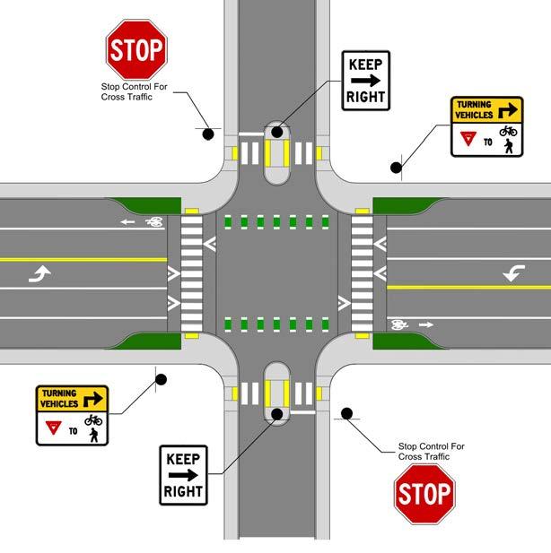
A raised intersection is when the full intersection, including the crosswalks, is raised sidewalk level to slow traffic and increase visibility for all users. This solution may be implemented with additional features like pavers to provide an opportunity for placemaking. FHWA recommends that raised intersections only be installed on roadways with 30 MPH or less. Drainage impacts should be evaluated.
Recommended Features
Raised Crossing, page 116
Raises the bike and/or pedestrian crossing to curb level to increase the visibility of people in the crosswalk, also helping to slow vehicle traffic.
Optional Features
Curb Extensions, page 108
Curb extensions extend the curb at crossing locations to improve visibility of people in the crossing and slow turning drivers.
Curb Radii, page 109
Tightening curb radii requires drivers to slow down when turning and increases the visibility of people crossing on foot or bike. This option is a minimum treatment; curb extensions are preferred.
Conflict Striping, page 122
Conflict striping defines the potential areas of conflict between people biking and people driving and also indicates to people biking the intended pathway through the intersection.
The intersection concept shown is an example of how treatments could be combined to create a comfortable crossing for people biking. For formal design guidance, refer to the following documents or others, as new guidance becomes available:
• FHWA MUTCD
• NACTO Urban Street Design Guide: Raised Intersections
• AASHTO Guide for the Planning, Design, and Operation of Pedestrian Facilities
• AASHTO A Policy on Geometric Design of Highways and Streets
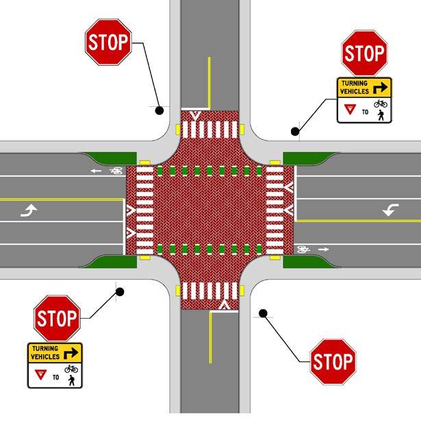
Neighborhood traffic circles are typically raised, circular elements are placed in the intersection to slow drivers. They provide an opportunity for placemaking as the raised elements can also be installed with planters or other beautifying elements. This solution is less ideal for locations where there is significant walking expected and may or may not be installed with stop control.
Curb Radii, page 109
Tightening curb radii requires drivers to slow down when turning and increases the visibility of people crossing on foot or bike. This option is a minimum treatment; curb extensions are preferred.
Crossing, page 116
Raises the bike and/or pedestrian crossing to curb level to increase the visibility of people in the crosswalk, also helping to slow vehicle traffic.
Curb Extensions, page 108
Curb extensions extend the curb at crossing locations to improve visibility of people in the crossing and slow turning drivers.
Reference Documents
Median refuge islands are protected spaces in the median and allow people crossing on foot or bike to cross one direction of traffic at a time. They can also help to slow traffic and improve user comfort.
Directional markers indicate the intended path for biking through the intersection and increase the visibility of people biking to drivers.
The intersection concept shown is an example of how treatments could be combined to create a comfortable crossing for people biking. For formal design guidance, refer to the following documents or others, as new guidance becomes available:
• FHWA MUTCD
• NACTO Urban Bikeway Design Guide: Minor Street Crossings
• AASHTO Guide for the Planning, Design, and Operation of Pedestrian Facilities
• AASHTO A Policy on Geometric Design of Highways and Streets
• NCHRP Research Report 1043: Guide for Roundabouts
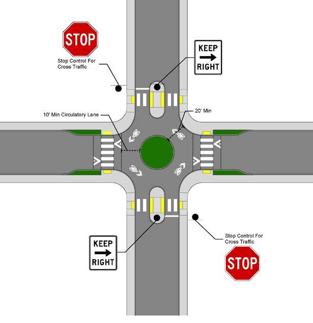
A mini roundabout is intended to keep speeds to a minimum and should provide approximately keep 15 feet of clearance from the corner to the widest point of the circle.
A center island prevents through traffic for vehicles but provides a protected space for people walking and biking to wait for gaps in traffic and cross the road one direction at a time. Median diverters are typically used where a lower stress bike facility such as a bike boulevard intersects with a higher volume or higher speed street. The median can be designed to be mountable for emergency access.
Recommended Features
Tighten Curb Radii, page 109
Tightening curb radii requires drivers to slow down when turning and increases the visibility of people crossing on foot or bike. This option is a minimum treatment; curb extensions are preferred.
Conflict Striping, page 122
Conflict striping defines the potential areas of conflict between people biking and people driving and also indicates the intended path for people biking.
Median Refuge Islands, page 114
Median refuge islands are protected spaces in the median and allow people crossing on foot or bike to cross one direction of traffic at a time. They can also help to slow traffic and improve user comfort.
Raised Crossing, page 116
Raises the bike and/or pedestrian crossing to curb level to increase the visibility of people in the crosswalk, also helping to slow vehicle traffic.
Additional Reflective Markers
Reflective markers can be used on the approach in place of the KEEP RIGHT signs for more guidance see Section 31.02 of the MUTCD.
Directional Markers, page 123
Directional markers provide guidance to people biking how to proceed through the intersection. Typically used in complex or wide intersections and also increase the visibility of people biking to drivers.
Reflective Approach Edge
The approach edge of the refuge island shall be outlined in retroreflective white or yellow material.
Curb Extensions, page 108
Curb extensions extend the curb at crossing locations to improve visibility of people in the crossing and slow turning drivers.
Two-Stage Bicycle-Turn Queue Box, page 118, or Bike Box, page 107
These designated spaces provide space for people biking to stage ahead of traffic or make left turns at multi lane intersections in multiple signal stages. These treatments are only MUTCD compliant if the intersection is signalized.
The intersection concept shown is an example of how treatments could be combined to create a comfortable crossing for people biking. For formal design guidance, refer to the following documents or others, as new guidance becomes available:
• FHWA MUTCD, 11th Edition, Part 9
• NACTO Urban Bikeway Design Guide: Major Street Crossings
• AASHTO Guide for the Planning, Design, and Operation of Pedestrian Facilities
• AASHTO A Policy on Geometric Design of Highways and Streets

In both a partial and half-closure, vehicles are permitted to exit one leg of the intersection, but not enter while people walking and biking can proceed unimpeded in both directions. This can be achieved by either using an island (with an optional pedestrian refuge island) in the case of a partial closure, or by using a curb extension in the case of a half closure. Volume control measures such as partial/half closures should not be used along primary emergency response routes.
Recommended Features
Treatments should provide either a 4-foot minimum contra-flow bike lane or a 5-foot minimum opening between an island and curb to allow channeled bike access.
Curb Radii, page 109
Tightening curb radii requires drivers to slow down when turning and increases the visibility of people crossing on foot or bike.
Curb Extensions, page 108
Curb extensions extend the curb at crossing locations to reduce the crossing distance and slow turning drivers. In a half closure, the curb extension should be about 30 feet.
Crossing, page 116
Raises the bike and/or pedestrian crossing to curb level to increase the visibility of people in the crosswalk, also helping to slow vehicle traffic. Alternatively, the whole intersection could be raised.
Median refuge islands are protected spaces in the median and allow people crossing on foot or bike to cross one direction of traffic at a time. When used as a partial closure, the median island should be extended almost to the centerline.
The approach edge of the refuge island shall be outlined in retroreflective white or yellow material.
Reflective markers can be used on the approach in place of the KEEP RIGHT signs for more guidance see Section 31.02 of the MUTCD.
The intersection concept shown is an example of how treatments could be combined to create a comfortable crossing for people biking. For formal design guidance, refer to the following documents or others, as new guidance becomes available:
• FHWA MUTCD
• NACTO Urban Bikeway Design Guide: Major Street Crossings
• AASHTO Guide for the Planning, Design, and Operation of Pedestrian Facilities
• AASHTO A Policy on Geometric Design of Highways and Streets
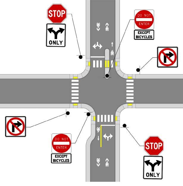
Vehicular traffic is channelized to take either a right or left turn but people walking and biking can proceed through. Diverters can be designed with landscaping to support placemaking and stormwater drainage, or with cut outs to maintain existing flowlines.
Recommended Features
Directional Markers, page 123
Directional markers indicate the intended path for biking through the intersection and increase the visibility of people biking to drivers.
Median Island or Raised Feature
A2
A median island is placed in the middle of the diverter to prevent vehicles from driving through. It may be mountable for emergency vehicle access.
Optional Features
Curb Extensions, page 108
Curb extensions extend the curb at crossing locations to improve visibility of people in the crossing and slow turning drivers.
Raised Crossing, page 116
Raises the bike and/or pedestrian crossing to curb level to increase the visibility of people in the crosswalk, also helping to slow vehicle traffic.
Reference Documents
Tighten Curb Radii, page 109
Tightening curb radii requires drivers to slow down when turning and increases the visibility of people crossing on foot or bike. This option is a minimum treatment; curb extensions are preferred.
Reflective markers can be used on the approach in place of the KEEP RIGHT signs for more guidance see Section 31.02 of the MUTCD.
The intersection concept shown is an example of how treatments could be combined to create a comfortable crossing for people biking. For formal design guidance, refer to the following documents or others, as new guidance becomes available:
• FHWA MUTCD
• NACTO Urban Bikeway Design Guide: Major Street Crossings
• AASHTO Guide for the Planning, Design, and Operation of Pedestrian Facilities
• AASHTO A Policy on Geometric Design of Highways and Streets
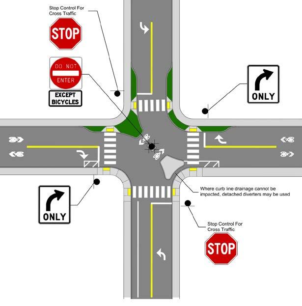
Diagonal diverters should have clear widths sufficient for single-unit trucks to make turns without encroaching on opposing lanes
Bike boxes and two-stage bicycle-turn queue boxes can be used as elements to enhance other intersection solutions or used alone to make up the bike box Intersection.
Recommended Features
Bike Box, page 107
Bike boxes provide designated spaces for people biking to queue in front of vehicles and/ or transition to left turn lanes at red lights.
Two-Stage Bicycle-Turn Queue Box, page 118
Queue boxes provide designated space for people biking to make left turns at multi lane intersections in multiple signal stages.
Optional Features
Bend-Outs, page 112
Bend outs allowing people biking to queue closer to the street crossing, improving visibility and providing yield space for right-turning drivers.
Centerline Hardening, page 106
A raised treatment is placed along the centerline, requiring drivers to slow down when making left turns.
Curb Extensions, page 108
Curb extensions extend the curb at crossing locations to improve visibility of people in the crossing and slow turning drivers.
Conflict Striping, page 122
Conflict striping defines the potential areas of conflict between people biking and people driving and also indicates the intended path for people biking.
Tighten Curb Radii, page 109
Tightening curb radii requires drivers to slow down when turning and increases the visibility of people crossing on foot or bike. This option is a minimum treatment; curb extensions are preferred.
Raised Crossing, page 116
Raises the bike and/or pedestrian crossing to curb level to increase the visibility of people in the crosswalk, also helping to slow vehicle traffic.
Median Refuge Islands, page 114
Median refuge islands are protected spaces in the median and allow people crossing on foot or bike to cross one direction of traffic at a time.
The intersection concept shown is an example of how treatments could be combined to create a comfortable crossing for people biking. For formal design guidance, refer to the following documents or others, as new guidance becomes available:
• FHWA MUTCD, 11th Edition, Part 9
• NACTO Urban Bikeway Design Guide: Major Street Crossings
• AASHTO Guide for the Planning, Design, and Operation of Pedestrian Facilities
• AASHTO A Policy on Geometric Design of Highways and Streets
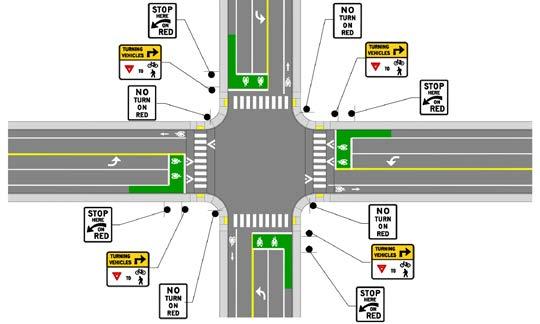
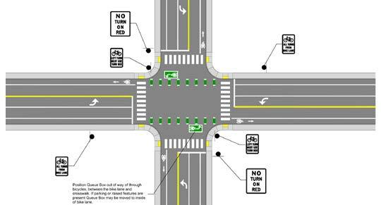
Position Queue Box out of way of through bicycles, between the bike lane and crosswalk. If parking or raised features are present, Queue Box may be moved to inside of bike lane
Roundabouts slow traffic while maintaining continuous vehicle flow through an intersection. When paired with a protected bike lane, the roundabout maintains separation between modes through the intersection. They may also be paired with raised crossings to further slow traffic.
Recommended Features
Conflict Striping, page 122
Conflict striping defines the potential areas of conflict between people biking and people driving and also indicates to people biking the intended pathway through the intersection.
Splitter Islands
A2
Splitter islands slow vehicular traffic approaching the roundabout and help to guide drivers to the right when they reach the circular part of the intersection.
Optional Features
Raised Crossing, page 116
B1
Median Refuge Islands, page 114
Median refuge islands are protected spaces in the median and allow people crossing on foot or bike to cross one direction of traffic at a time. They can also help to slow traffic and improve user comfort.
Raises the bike and/or pedestrian crossing to curb level to increase the visibility of people in the crosswalk, also helping to slow vehicle traffic.
Bikeway Protection
Where a protected bikeway approaches a roundabout, or where additional comfort and separation is desired, medians or other vertical barriers can be used to protect the bikeway through the roundabout. Where this treatment is applied, crosswalks and appropriate ADA ramps and features must be applied, similar to a protected intersection (page 90) or bend out (page 112). If the bikeway is not protected though the intersection, a ramp may be provided and bicycle traffic make travel along a shared sidepath through the intersection.
Reference Documents
The intersection concept shown is an example of how treatments could be combined to create a comfortable crossing for people biking. For formal design guidance, refer to the following documents or others, as new guidance becomes available:
• FHWA MUTCD, 11th Edition, Part 9
• NACTO Urban Bikeway Design Guide: Major Street Crossings
• AASHTO Guide for the Planning, Design, and Operation of Pedestrian Facilities
• AASHTO A Policy on Geometric Design of Highways and Streets
• NCHRP Research Report 1043: Guide for Roundabouts
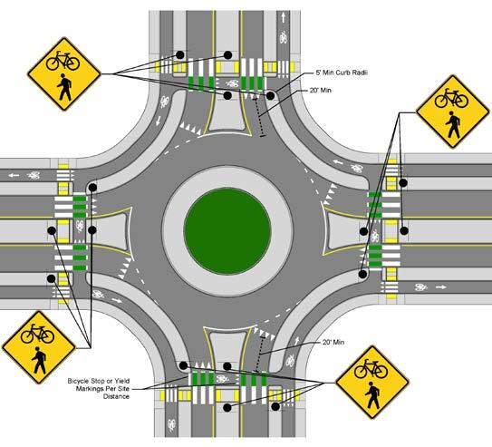
People biking are given a dedicated path to traverse through the intersection, reducing the conflict points between people biking and motorists especially when the treatment is combined with protected-permissive bike signal phasing. They are typically used when there is not enough space for a full protected intersection. While dedicated intersections do not provide as much space for turning drivers to yield to people in the crosswalk or crossbike, they do have a traffic calming benefit.
Recommended Features
Centerline Hardening, page 106
A raised treatment is placed along the centerline, requiring drivers to slow down when making left turns.
Corner wedge islands are small, raised wedges, which require drivers to slow down when making right turns and provide a small level of physical separation for people biking. They may be mountable to accommodate larger vehicles.
Centerline Hardening, page 106
A raised treatment is placed along the centerline, requiring drivers to slow down when making left turns.
Optional Features B1
Median Refuge Islands, page 114
Median refuge islands are protected spaces in the median and allow people crossing on foot or bike to cross one direction of traffic at a time. They can also help to slow traffic and improve user comfort.
Using a combination of leading bike and pedestrian interval can be provided if a shared through/turn lane is next to the bikeway. If a dedicated right or left turn lane is next to the bikeway, a protected-permissive bike signal phase should be considered.
Bike Lane Yield Markings and Crosswalks, page 123
Communicates to people biking to yield to people walking across the bikeway to wait at the median island. Also indicates where people walking should cross. Detectable warning surfaces shall be placed before and after the crossing of the bikeway.
Crosswalk separators are small raised elements between the crosswalk and crossbike to help provide guidance for people with visual impairments.
The intersection concept shown is an example of how treatments could be combined to create a comfortable crossing for people biking. For formal design guidance, refer to the following documents or others, as new guidance becomes available:
• FHWA MUTCD, 11th Edition, Part 9
• NACTO Urban Bikeway Design Guide: Major Street Crossings
• AASHTO Guide for the Planning, Design, and Operation of Pedestrian Facilities
• AASHTO A Policy on Geometric Design of Highways and Streets
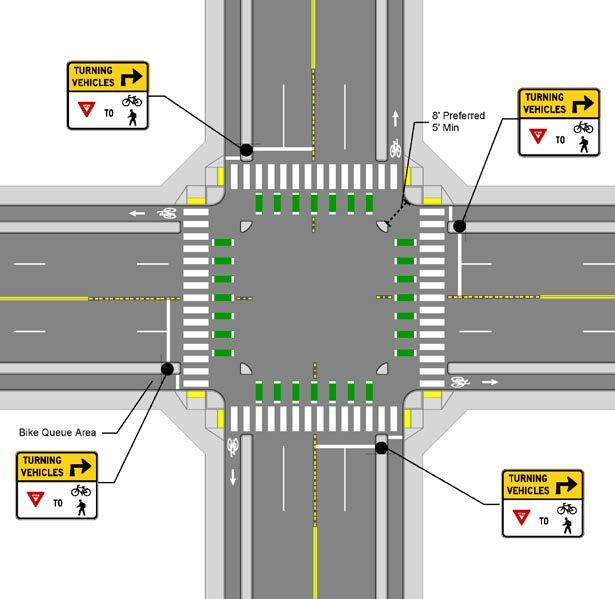
People biking are given a dedicated path to traverse through the intersection, providing physical separation throughout the intersection only exposing people biking when crossing vehicle travel lanes.
Recommended Features
The driver yield zone provides space for turning vehicles to yield to people crossing. The preferred offset distance between the crossing and adjacent street is 16 feet to allow for one full vehicle to queue, but may be as low as 6 feet in constrained situations or as wide as 24 feet where higher vehicle speeds are anticipated.
Corner islands provide physical separation between the bikeway and moving vehicles. The curb radius of the corner island should be designed to slow turning vehicle speeds to 15 mph or less. The corner island may include a mountable truck apron where needed.
This area provides space for people biking to queue prior to crossing the intersection. The bike queue area should be a minimum of 6.5 feet deep, but dimensions of 10 feet or greater can accommodate higher bike volumes and longer bikes
If a lateral shift is required to position the bikeway, a gentle shift is preferred. The preferred taper is 1:4 or 1:5.
Optional Features
Median Refuge Islands, page 114
Median refuge islands are protected spaces in the median and allow people crossing on foot or bike to cross one direction of traffic at a time. They can also help to slow traffic and improve user comfort.
Conflict Striping, page 122
Conflict striping defines the potential areas of conflict between people biking and people driving and also indicates to people biking the intended pathway through the intersection.
A leading pedestrian interval with a concurrent bike signal phase may be used to provide people walking and biking with a head start, although a dedicated bike phase is preferred. In either event, right turns on red should be prohibited.
Where the bikeway is at sidewalk level, a detectable edge should be placed between the bikeway and sidewalk.
Lane
and Crosswalks, page 123
Communicates to people biking to yield to people walking across the bikeway to wait at the median island. Also indicates where people walking should cross. Detectable warning surfaces shall be placed before and after the crossing of the bikeway.
Crosswalk separators are small raised elements between the crosswalk and crossbike to help provide guidance for people with visual impairments.
The intersection concept shown is an example of how treatments could be combined to create a comfortable crossing for people biking. For formal design guidance, refer to the following documents or others, as new guidance becomes available:
• FHWA MUTCD, 11th Edition, Part 9
• NACTO Urban Bikeway Design Guide: Major Street Crossings
• AASHTO Guide for the Planning, Design, and Operation of Pedestrian Facilities
• AASHTO A Policy on Geometric Design of Highways and Streets
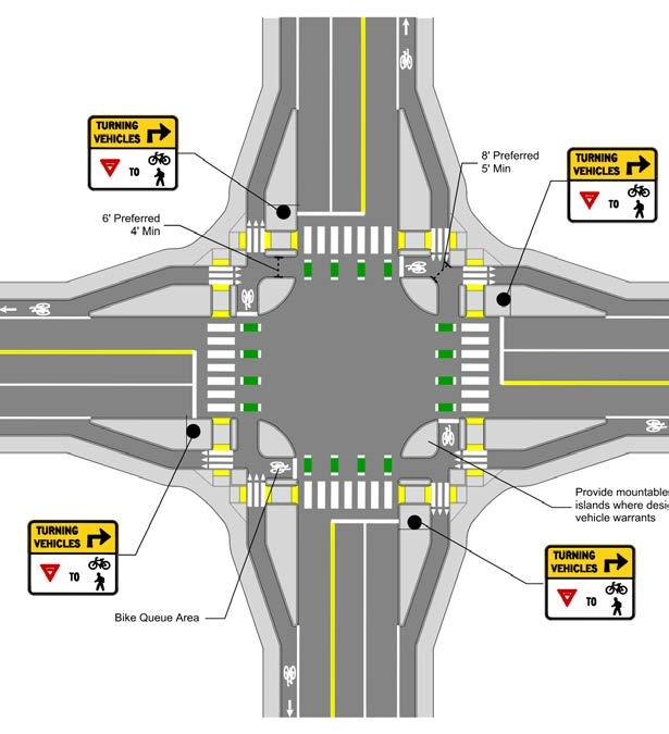

Page Intentionally Left Blank

Active transportation facilities require special considerations for midblock, side street, and driveway crossings.
Midblock crossings occur outside of an intersection, and are often installed to support shared use path crossings. These crossings require additional consideration to alert drivers of the potential for people crossing, as they may not expect the crossing outside of a signalized intersections.
Bikeways and shared use paths also require additional consideration when crossing side streets or driveways. In these locations, the bikeway or shared use path should be designed to minimize conflict between people crossing on foot or bike and drivers turning into our out of the side street or driveway. While conflict markings and crosswalks alone may be sufficient in many places, side streets and driveways which are heavily utilized, which have experienced crashes between turning vehicle and people walking and biking, or where additional comfort is desired, additional treatments may be considered.
Where shared use paths cross streets, the crossing may be elevated to the same height as the sidewalk. A raised crossing helps increase visibility of people using the path to people driving. The raised crossing also helps to slow down drivers when they travel over the raised portion, helping increase driver reaction time and increase yielding to people in the crossing.
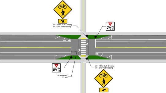
A1 Stop Lines
Stop lines at midblock crossings should be set back 20 – 50 feet to ensure that a person crossing is visible.
A2 Median Refuge Islands, page 114
Median refuge islands are protected spaces in the median and allow people crossing on foot or bike to cross one direction of traffic at a time. They can also help to slow traffic and improve user comfort.
A3
Curb Extensions, page 108
Curb extensions extend the curb at crossing locations to improve visibility of people in the crossing and slow turning drivers.
Bike Lane Yield Markings and Crosswalks, page 123
Communicates to people biking to yield to people walking across the bikeway to wait at the median island. Also indicates where people walking should cross. Detectable warning surfaces shall be placed before and after the crossing of the bikeway.
The intersection concept shown is an example of how treatments could be combined to create a comfortable crossing for people biking. For formal design guidance, refer to the following documents or others, as new guidance becomes available:
• FHWA MUTCD
• NACTO Urban Bikeway Design Guide: Mid Block Crosswalks
• AASHTO Guide for the Planning, Design, and Operation of Pedestrian Facilities
• AASHTO A Policy on Geometric Design of Highways and Streets
A midblock signal is a traffic control device intended to facilitate safe crossings for people walking or biking particularly across higher-stress roadways. The signal is activated by push button by a person walking or biking who intends to cross but can be automated through detection systems.

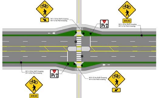
Recommended Features
A1 Stop Lines
Stop lines at midblock crossings should be set back 20 – 50 feet to ensure that a person crossing is visible.
A2 Median Refuge Islands, page 114
Median refuge islands are protected spaces in the median and allow people crossing on foot or bike to cross one direction of traffic at a time. They can also help to slow traffic and improve user comfort.
A3 Curb Extensions, page 108
Curb extensions extend the curb at crossing locations to improve visibility of people in the crossing and slow turning drivers.
Bike Lane Yield Markings and Crosswalks, page 123
Communicates to people biking to yield to people walking across the bikeway to wait at the median island. Also indicates where people walking should cross. Detectable warning surfaces shall be placed before and after the crossing of the bikeway.
The intersection concept shown is an example of how treatments could be combined to create a comfortable crossing for people biking. For formal design guidance, refer to the following documents or others, as new guidance becomes available:
• FHWA MUTCD
• NACTO Urban Bikeway Design Guide: Mid Block Crosswalks
• AASHTO Guide for the Planning, Design, and Operation of Pedestrian Facilities
• AASHTO A Policy on Geometric Design of Highways and Streets
When protected bike lanes are provided at sidewalk level, it is often more comfortable to provide raised crossings across side streets and driveways to avoid frequent elevation changes. Additionally, raised crossing can help to slow turning vehicles and improve visibility of people walking and biking. This solution is most effective when utilized consistently across a corridor, especially along multi-lane or higher volume roads.
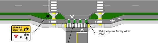

Recommended Features
A1
Raised Crossing, page 116
Raises the bike and/or pedestrian crossing to curb level which increase the visibility of people in the crosswalk and slows drivers as they pass the raised element.
A2 Bend-Outs, page 112
Bend outs allowing people biking to queue closer to the street crossing, improving visibility and providing yield space for right-turning drivers.
Optional Features
B1 Curb Extensions, page 108
Curb extensions extend the curb at crossing locations to improve visibility of people in the crossing and slow turning drivers.
A3 Conflict Striping, page 122
Conflict striping defines the potential areas of conflict between people biking and people driving and also indicates to people biking the intended pathway through the intersection.
Bike Lane Yield Markings and Crosswalks, page 123
Communicates to people biking to yield to people walking across the bikeway to wait at the median island. Also indicates where people walking should cross. Detectable warning surfaces shall be placed before and after the crossing of the bikeway.
B2 Median Refuge Islands, page 114
Median refuge islands are protected spaces in the median and allow people crossing on foot or bike to cross one direction of traffic at a time. They can also help to slow traffic and improve user comfort.
The intersection concept shown is an example of how treatments could be combined to create a comfortable crossing for people biking. For formal design guidance, refer to the following documents or others, as new guidance becomes available:
• FHWA MUTCD, 11th Edition, Part 9
• NACTO Urban Bikeway Design Guide: Mid Block Crosswalks
• AASHTO Guide for the Planning, Design, and Operation of Pedestrian Facilities
• AASHTO A Policy on Geometric Design of Highways and Streets
When shared use paths and sidepath cross driveways and side streets, it is often more comfortable to provide raised crossings across side streets and driveways to avoid frequent elevation changes. Additionally, raised crossing can help to slow turning vehicles and improve visibility of people walking and biking. This solution is most effective when utilized consistently across a corridor, especially along multi-lane or higher volume roads.
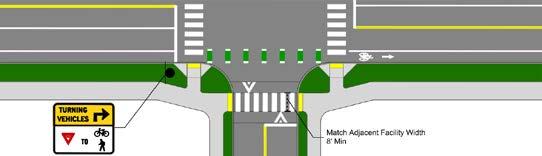
A1
Raised Crossing, page 116
Raises the bike and/or pedestrian crossing to curb level which increase the visibility of people in the crosswalk and slows drivers as they pass the raised element.
B1
Curb Extensions, page 108
Curb extensions extend the curb at crossing locations to improve visibility of people in the crossing and slow turning drivers.
A3 Bend-Outs, page 112
Bend outs allowing people biking to queue closer to the street crossing, improving visibility and providing yield space for right-turning drivers.
B2 Bike Lane and Conflict Striping, page 122
While most people may be more comfortable biking shared use paths, some may prefer to travel on street in bike lanes to avoid interacting with people walking. If bike lanes are provided adjacent to a shared use path conflict striping may be painted at intersections and driveways.
The intersection concept shown is an example of how treatments could be combined to create a comfortable crossing for people biking. For formal design guidance, refer to the following documents or others, as new guidance becomes available:
• FHWA MUTCD, 11th Edition, Part 9
• NACTO Urban Bikeway Design Guide: Mid Block Crosswalks
• AASHTO Guide for the Planning, Design, and Operation of Pedestrian Facilities
• AASHTO A Policy on Geometric Design of Highways and Streets

Page Intentionally Left Blank

Slip lanes, or channelized right-turn lanes, present challenges for people biking and other roadway users. Slip lanes may encourage higher right-turning speeds which can reduce driver reaction time in the same area that people walking and biking must cross the intersection. Further, drivers using a slip lane must also split their attention between the pathway in front of them and where people may be crossing and to the left where oncoming traffic that they will be merging with. The following guidelines are recommended for existing intersections that are to be retrofitted to be more comfortable for people biking.
A raised crossing in the slip lane slows right-turning traffic through the slip lane, especially upon the approach of the crossing for people walking and biking. In this example, the bikeway transitions to sidewalk level into a shared use path to facilitate the crossing.
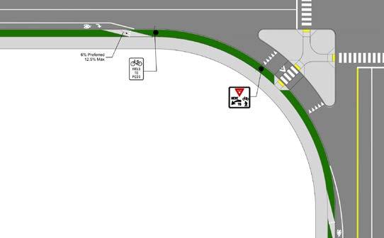
Recommended Features
A1 Conflict Striping, page 122
Conflict striping defines the potential areas of conflict between people biking and people driving and also indicates to people biking the intended pathway through the intersection.
A2 Yield Lines, page 123 Communicates to people driving to yield to people walking in the crosswalk and to yield to through traffic as they exit the slip lane.
A3 Raised Crossing, page 116
Raises the bike and/or pedestrian crossing to curb level which increase the visibility of people in the crosswalk and slows drivers as they pass the raised element.
A4 Through Bike Lane, page 110
Allows people biking to travel through the intersection along their original path of travel if they do not wish to transition off of the street.
The intersection concept shown is an example of how treatments could be combined to create a comfortable crossing for people biking. For formal design guidance, refer to the following documents or others, as new guidance becomes available:
• FHWA MUTCD, 11th Edition, Part 9
• NACTO Urban Bikeway Design Guide: Mid Block Crosswalks
• AASHTO Guide for the Planning, Design, and Operation of Pedestrian Facilities
• AASHTO A Policy on Geometric Design of Highways and Streets
Closes the slip lane to vehicular traffic but permits people biking. Drivers may turn right at the stop bar, but at slower speeds due to the tighter turning radii. In addition, closing the slip lane reduces the total number of potential conflicts between drivers and people walking and biking.
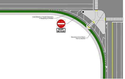
Recommended Features
A1 Lane Closure
Hatched paint or other quick-build materials such as flex posts can be used to help reinforce that the slip lane is closed to motorist and is only intended for smaller vehicles, or rather, people biking.
A2 Bike Lane Yield Lines, page 123
Communicates to people biking to yield to people walking in the cross walk and also to yield to through-bike traffic as they exit the slip lane.
A3 Raised Crossing, page 116
Raises the bike and/or pedestrian crossing to curb level which increase the visibility of people in the crosswalk and slows drivers as they pass the raised element.
A4 Through Bike Lane, page 110
Allows people biking to travel through the intersection along their original path of travel if they do not wish to transition off of the street.
The intersection concept shown is an example of how treatments could be combined to create a comfortable crossing for people biking. For formal design guidance, refer to the following documents or others, as new guidance becomes available:
• FHWA MUTCD, 11th Edition, Part 9
• NACTO Urban Bikeway Design Guide: Mid Block Crosswalks
• AASHTO Guide for the Planning, Design, and Operation of Pedestrian Facilities
• AASHTO A Policy on Geometric Design of Highways and Streets
The bike lane is transitioned to a protected intersection treatment in the island next to the slip lane. The bike lane utilizes the raised crossing, which slows down drivers and increases visibility of people crossing the slip lane.
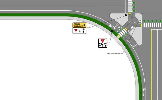
A1 Conflict Striping, page 122
Conflict striping defines the potential areas of conflict between people biking and people driving and also indicates to people biking the intended pathway through the intersection.
A2 Yield Lines, page 123
Communicates to people driving to yield to people walking in the crosswalk and to yield to through traffic as they exit the slip lane.
A3 Raised Crossing, page 116
Raises the bike and/or pedestrian crossing to curb level which increase the visibility of people in the crosswalk and slows drivers as they pass the raised element.
A4 Through Bike Lane, page 110
Allows people biking to travel through the intersection along their original path of travel if they do not wish to transition off of the street.
Bike Lane Yield Lines and Crosswalks, page 123
Communicates to people biking to yield to people walking across the bikeway to wait at the median island. Also indicates where people walking should cross. Detectable warning surfaces shall be placed before and after the crossing of the bikeway.
Where the bikeway is at sidewalk level, a detectable edge should be placed between the bikeway and sidewalk.
This area provides space for people biking to queue prior to crossing the intersection. The bike queue area should be a minimum of 6.5 feet deep, but dimensions of 10 feet or greater can accommodate higher bike volumes and longer bikes
The intersection concept shown is an example of how treatments could be combined to create a comfortable crossing for people biking. For formal design guidance, refer to the following documents or others, as new guidance becomes available:
• FHWA MUTCD, 11th Edition, Part 9
• NACTO Urban Bikeway Design Guide: Mid Block Crosswalks
• AASHTO Guide for the Planning, Design, and Operation of Pedestrian Facilities
• AASHTO A Policy on Geometric Design of Highways and Streets

Page Intentionally Left Blank

Page Intentionally Left Blank

Intersection Elements can be applied as independent intersection treatments; however, they are typically used in conjunction with others. The Intersection Typologies provide both a process for selecting intersection solutions that utilize these Intersection Elements and provide design guidance on where they are appropriate to apply.
It is recommended to start the design process at the Intersection Typologies which cross-reference the Intersection Elements and their respective design details in this section. While this chapter aims to provide the Intersection Elements design details at length, it only encompasses the Elements used within the Intersection Typologies recommended in this document and are not exhaustive of all potential treatments or solutions.
Centerline hardening involves placing a raised treatment in the centerline of the street to require drivers to make slower, wider left turns. This treatment increases the visibility for drivers of people crossing the street on foot or bike The raised treatment may be a concrete median is there is 4 feet or more in width, although more typically includes the use of mountable features designed to be highly visible such as small rubber speed bumps, or other small raised and highly visible islands, however, where more significant calming is needed, flexible delineators may ale be used. The treatment typically includes a raised element both approaching the crosswalk and a separate raised element placed after the crosswalk and extending into the intersection.
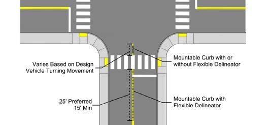
Recommended Features
Hardened centerline should be composed of a raised, vertical element in the centerline of the road.
The length and width of a hardened centerline varies, but they are often between 15 and 30 feet in length.
Retroreflective markings should be included on the centerline treatment to increase visibility by drivers.
The hardened centerline should include a segment of hardening approaching the crosswalk and a separate nose that extends from the edge of the crosswalk into the intersection. The extent may vary.
Optional Features
A flexible delineator mat be installed on the nose of the hardened centerline to increase visibility.
The hardened centerline may be designed to be mountable.
Where there is enough space (at least 6 feet), the hardened centerline can be designed as a median refuge island with a median nose.
For formal design guidance, refer to the following documents or others, as new guidance becomes available:
• FHWA MUTCD
• NACTO Don't Give Up at The Intersection
• AASHTO Guide for the Planning, Design, and Operation of Pedestrian Facilities
• AASHTO A Policy on Geometric Design of Highways and Streets
Bike boxes are designated spaces at intersections that allow people on bikes to queue in front of motor vehicles at red lights. They increase the visibility of people on bikes, provide a space for them to make left turns or transition to left turn lanes, and can give them a head start on green lights. Bike boxes should be extended across all vehicle lanes but may not be as comfortable on roads with two or more lanes in each direction.
Recommended Features
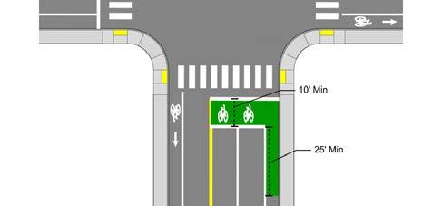
Bike boxes shall be a minimum of 10 feet deep and shall be marked on all sides by a white line. Deeper bike boxes may have better compliance.
Bike boxes should span all through travel lanes.
The bike box should be placed in advance of the crosswalk and a stop line shall indicate the point beyond which motor vehicles are required to stop. The bike box should be set back from the pedestrian crossing to minimize encroachment.
Optional Features
Bike boxes may be combined with exclusive bike signal phase or leading interval through the use of bike signal heads.
“Wait Here” text and “Stop Here on Red” with “Except Bicycles” (MUTCD R10-6a, R3-7bP) signage may be used to supplement the stop line.
Reference Documents
Right turns on red shall be prohibited from the lane where the bike box is placed. However, if a right turn lane is present, the bike box may be placed in front of the through travel lane and right turns on red may be permitted from the right turn lane. Where right turns on red are prohibited, “No Turn On Red” (MUTCD R10-11) signage shall be utilized.
At least one bicycle marking should be present in the bike box.
Bike boxes should be painted green.
Active display / blank out signs may be utilized to increase visibility for NO RIGHT TURN ON RED signage (MUTCD R10-11).
For formal design guidance, refer to the following documents or others, as new guidance becomes available:
• FHWA MUTCD, 11th Edition, Part 9
• NACTO Urban Bikeway Design Guide
• AASHTO Guide for the Planning, Design, and Operation of Pedestrian Facilities
• AASHTO A Policy on Geometric Design of Highways and Streets
Curb extensions extend the curb at crossing locations to reduce the crossing distance and slow turning drivers. Additionally, where on street parking is present, curb extensions provide opportunity for “daylighting,” which involves restricting parking within 20’ of the crosswalk to improve visibility of people waiting to cross and turning vehicles. They may be constructed with concrete or may be built with quick build solutions such as a combination of flexible delineators, paint, and/or other raised elements.
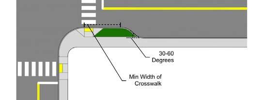
Recommended Features
The length of a curb extension should be as wide or wider than the crosswalk, but may extend to the advanced stop bar.
Curb extensions shall be designed with pedestrian ramps and tactile warning surfaces per ADA. Where feasible, directional ramps should be used to provide proper positioning for people with visual impairments.
Optional Features
The curb radius of the curb extension should be designed to slow turning vehicle speeds to 15 mph or less. Where larger vehicles, such as delivery trucks, are frequently required to make a turn, a mountable truck apron may be used to allow for a wider turn radius for large vehicles while still discouraging smaller vehicles from wide or fast turn movements.
Bike racks may be placed in curb extensions.
Where bike facilities are present, a bend out treatment should be considered along with the curb extension to allow for through bicycle movement. Alternatively, the curb extension could be narrowed to allow for a bike lane to be placed between the vehicle lane and edge of the curb.
Curb extensions may be combined with additional stormwater features.
Curb extensions may also be placed mid-block to provide access to mid-block crossings and achieve a similar traffic calming feature.
For formal design guidance, refer to the following documents or others, as new guidance becomes available:
• FHWA MUTCD
• NACTO Urban Bikeway Design Guide
• AASHTO Guide for the Planning, Design, and Operation of Pedestrian Facilities
• AASHTO A Policy on Geometric Design of Highways and Streets
Tightening curb radii requires vehicles to slow down when turning, which helps to reduce the risk of right turning drivers hitting people crossing in the bikeway or crosswalk. This treatment can also be used to realign skewed intersections to right angles. Additional benefits of this treatment include providing additional space for directional curb ramps and reducing pedestrian crossing widths. They may be constructed with concrete or may be built with quick build solutions such as a combination of flexible delineators, paint, and/or other raised elements.
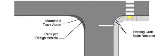
The curb radius of the curb extension should be designed to slow turning vehicle speeds to 15 mph or less. Where larger vehicles, such as delivery trucks, are frequently required to make a turn, a mountable truck apron may be used to allow for a wider turn radius for large vehicles while still discouraging smaller vehicles from wide or fast turn movements.
Intersection geometry changes supported by tightened turn radii may provide space for additional stormwater features.
If the treatment is placed at a skewed intersection, the intersection should be realigned to a right angle where possible.
Pedestrian crossings shall be designed with pedestrian ramps and tactile warning surfaces per ADA. Where feasible, directional ramps should be used to provide proper positioning for people with visual impairments.
Additional vertical elements may be used to reinforce the tighter radius, including paint, flexible delineators, and rubber curbs / armadillos.
For formal design guidance, refer to the following documents or others, as new guidance becomes available:
• FHWA MUTCD
• NACTO Urban Bikeway Design Guide
• AASHTO Guide for the Planning, Design, and Operation of Pedestrian Facilities
• AASHTO A Policy on Geometric Design of Highways and Streets
The bikeway remains adjacent to the curb to the right of the right-turn lane. This treatment maintains separation between drivers and people biking, but additional care may be needed to alert right turning drivers to the presence of people biking. This can be accomplished through additional signage, no right turn on red, or a bike signal phase.
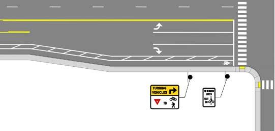
Recommended Features
The bike lane remains adjacent to the curb; a right turn lane should be placed to the left of the bike lane.
Optional Features
B1
Right turns on red shall be prohibited. Where right turns on red are prohibited, “No Turn On Red” (MUTCD R10-11) signage shall be utilized.
A bike box may be painted to allow people biking a chance to queue in front of vehicles or position themselves to turn left.
Reference Documents
For formal design guidance, refer to the following documents or others, as new guidance becomes available:
• FHWA MUTCD
• NACTO Urban Bikeway Design Guide
• AASHTO Guide for the Planning, Design, and Operation of Pedestrian Facilities
• AASHTO A Policy on Geometric Design of Highways and Streets
The bikeway is shifted to the left of the right-turn lane. This treatment may not be comfortable for all users, as drivers and people biking must switch places. However, this treatment reduces conflicts between right turning vehicles and through moving bicyclists.
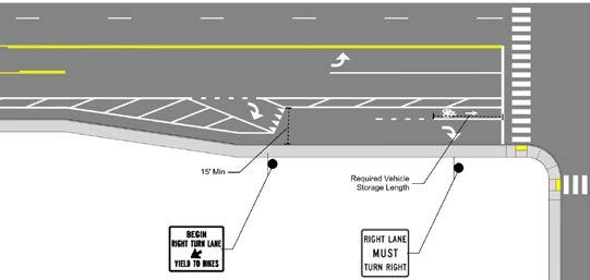
Recommended Features
A1
A gentle shift is preferred. The minimum taper that should be used is 3:1.
Yield lines may be used prior to the bike lane shift to indicate to drivers to yield to people crossing on bike.
For formal design guidance, refer to the following documents or others, as new guidance becomes available:
• FHWA MUTCD
• NACTO Urban Bikeway Design Guide
• AASHTO Guide for the Planning, Design, and Operation of Pedestrian Facilities
• AASHTO A Policy on Geometric Design of Highways and Streets
Bend outs operate similar to a protected intersection, allowing people biking to way to queue closer to the street crossing. This placement allows for turning drivers to have a better view of people biking, and also provide space for a driver to yield to people crossing on bike or on foot. The bikeway may run at street or sidewalk level through the bend out. If at sidewalk level, a detectable edge should be placed between the bikeway and sidewalk marked crosswalks should guide people crossing the bikeway. They may be constructed with concrete or may be built with quick build solutions such as a combination of flexible delineators, paint, and/or other raised elements.
A note on bend-ins: Another type of intersection treatment involves bending the bikeway in toward the vehicle lane prior to the crossing. This treatment is generally not recommended as it does not provide the increased visibility or yielding space that a bend-out does.
Recommended Features
The preferred offset distance between the crossing and adjacent street is 16 feet, but may be as low as 6 feet in constrained situations or as wide as 24 feet where higher vehicle speeds are anticipated. 16 feet allows for one full vehicle to queue prior to the crossing, although there is still improved visibility with offsets of 6-16 feet.
If a lateral shift is required to position the bikeway, a gentle shift is preferred. The preferred taper is 1:4 or 1:5.
A3
The curb radius of the curb extension should be designed to slow turning vehicle speeds to 15 mph or less. Where larger vehicles, such as delivery trucks, are frequently required to make a turn, a mountable truck apron may be used to allow for a wider turn radius for large vehicles while still discouraging smaller vehicles from wide or fast turn movements.
Yield markings may be installed where people walking are anticipated to cross the bikeway to further indicate priority users.
Optional Features
Refuge islands may be placed between the bikeway and driving lane to allow space for people crossing on foot or bike to queue.
Marked pedestrian crosswalks shall be placed through the bikeway at the crossing point. Detectable warning surfaces shall be placed before and after the crossing of the bikeway.
Where the bikeway is at sidewalk level, a detectable edge should be placed between the bikeway and sidewalk.
Consideration should be given for vehicles turning across the bikeway. A leading pedestrian interval with a concurrent bike signal phase may be used to provide people walking and biking with a head start, or a dedicated through phase may be provided for people walking and biking. In either event, right turns on red should be prohibited and “NO TURN ON RED” (MUTCD R10-11) signage shall be installed. A bike signal with A “TURNING VEHICLES YIELD TO BICYCLES AND PEDESTRIANS” sign (R10-15) should be used where right turning vehicles are not restricted during the through phase for people walking and biking.
For formal design guidance, refer to the following documents or others, as new guidance becomes available:
• FHWA MUTCD, 11th Edition, Part 9
• NACTO Urban Bikeway Design Guide
• AASHTO Guide for the Planning, Design, and Operation of Pedestrian Facilities
• AASHTO A Policy on Geometric Design of Highways and Streets
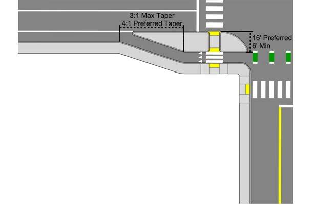
Median refuge islands are protected spaces in the median and allow people crossing on foot or bike to cross one direction of traffic at a time. They may also be placed between the bikeway and vehicle lane, especially when used in conjunction with protected bike lanes. They can help to slow traffic and are especially useful at improving comfort for people walking and biking on multi-lane roads. They can be used at intersections or mid-block. They may be constructed with concrete or may be built with quick build solutions such as a combination of flexible delineators, paint, curb stops, and/or other raised elements.
Refuge spaces within refuge islands should be at least 10 feet wide to allow space for both people walking and biking, but they may be as narrow as 6 feet in constrained areas. Generally, the width of the refuge space should match the width of the connecting facility.
The curb of the island facing approaching vehicles shall be outlined in retroreflective white or yellow material. Additional reflective markers and or delineator posts should also be considered.
The height of the island should be 6 inches.
The waiting area for the refuge island should be at street level, but shall include tactile warning surfaces per ADA.
It is desirable to include a median on both sides of the refuge area.
Pedestrian warning (MUTCD W11-2) signs or Bicycle and Pedestrian warning (MUTCD W1115) signage should be used to indicate to approaching vehicles to watch for people crossing.
If intended for use by both people walking and biking, the refuge area should be wide enough to accommodate both people walking and biking.
If intended for use by both people walking and biking, conflict markings / crossbikes should be marked in addition to crosswalks.
Additional reflective markers should be considered on the nose of the island.
The refuge island may be designed with an angled cut through to position people walking or biking to face oncoming traffic. If the refuge is shared with people on foot, the angle should transition back to being perpendicular with the street at the crossing points to provide proper positioning for people with visual impairments.
Landscaping may be added in the median but should not obstruct visibility.
Additional lighting may be desired to improve visibility.
If a median is extended through the intersection as a diverter, separated refuge spaces may be included for people walking and biking within the path of travel for each mode. For example, the refuge for people walking should be placed in the path of the crosswalk, while the bike refuge may be placed towards the center of the intersection. In such a case, enough space should be provided for two-way bicycle traffic.
For formal design guidance, refer to the following documents or others, as new guidance becomes available:
• FHWA MUTCD
• NACTO Urban Bikeway Design Guide
• AASHTO Guide for the Planning, Design, and Operation of Pedestrian Facilities
• AASHTO A Policy on Geometric Design of Highways and Streets
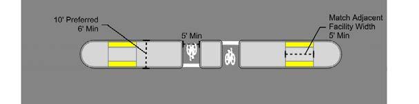
The crosswalk area may be raised to sidewalk level to increase visibility of people in the crosswalk. They can also have a traffic calming benefit, as people driving or biking over the raised crossing are required to slow down to pass the raised element. Raised crossings can be used in several different scenarios:
• Raised Pedestrian Crossing: The pedestrian street crossing may be raised at intersection, mid-block, or right turn slip lane crossings. The pedestrian crossing may also be raised across a protected bikeway at bus islands, accessible parking spaces, or loading zones.
• Raised Side Street or Driveway Crossing: At higher volume driveways, along routes with raised bikeways or shared use paths, or along routes with heavy volumes of people biking, the crossing may be raised. Where feasible, the crossing should be set back to allow for the right turning drivers to yield to people crossing the driveway. When used in this way, the crossing markings for people walking and biking should be incorporated into the raised element. or more information about design considerations and details, see the Side Streets section.
• Shared Use Path or Sidepath Crossing: Where a shared use path or sidepath crosses a street, it is often desirable to raise the path crossing. Crosswalk markings should be included, and crossbike / green conflict markings should also be included if the walkway and bikeway are separated. For more information about design considerations and details, see the Side Streets section.
PEDESTRIAN WARNING (MUTCD W11-2) signs or BICYCLE AND PEDESTRIAN WARNING (MUTCD W11-15) signs should be used to indicate to approaching vehicles to watch for people crossing. Recommended Features Optional Features
Raised crossings should be at sidewalk height, generally 6 inches high.
Raised crossings should typically be 10 feet wide or wider; where supporting a protected bike lane, match adjacent facility width.
Vertical deflection markings should be used on the approach side of the speed hump, as detailed here and in MUTCD Figure 3B-30.
Crosswalks should be marked in raised crosswalks. Where people biking are also anticipated to use the raised crossing, crossbikes / green conflict markings should be marked as well.
Detectable warning surfaces should be placed at the transition between the sidewalk and the crossing, and may extend across the bikeway.
Generally a 5-8% slope is recommended for raised crossings across streets. Across driveways and alleys, a slope of up to 15% may be used, but care should be taken to ensure as smooth a vehicle transition as possible.
Where raised crosswalks cross a bikeway, people biking should yield to people walking across the crosswalk, and additional signage, rumble strips, yield markings, or stop bars can be utilized to alert people biking to the presence of the crossing.
Where possible, the raised crossing should be set back from the intersection to allow vehicle traffic to queue in advance of the raised crossing.
For formal design guidance, refer to the following documents or others, as new guidance becomes available:
• FHWA MUTCD
• NACTO Urban Bikeway Design Guide
• AASHTO Guide for the Planning, Design, and Operation of Pedestrian Facilities
• AASHTO A Policy on Geometric Design of Highways and Streets
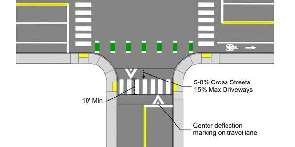

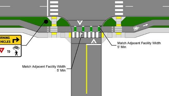
These boxes allow people biking to make left turns at multi lane intersections in stages and should be considered where a protected intersection is not provided. They allow people biking to position for left turns without merging into traffic. The placement and design may vary, but they should be placed to provide clear visibility of people on bikes by motorists. No turn on red restrictions should be used to prevent vehicles from entering the queuing area.
Recommended Features
Bicycle-turn queue boxes shall be a minimum of 10 feet deep and 6.5 feet in width and shall be marked on all sides by a white line.
Bicycle-turn queue boxes shall be placed in a protected area, typically in the on street parking lane or the bikeway buffer. If there is not a protected space for the queue box, a bike box may be placed behind the pedestrian crosswalk to serve the same purpose. For more information on potential placement for bicycle-turn queue boxes, see MUTCD Section 9E.11.
The bicycle-turn queue box should be positioned laterally within the cross street, allowing people on bikes to position themselves in the intended path of travel.
Optional Features
Guide lines, conflict markings, or other pavement features may be used to lead people biking to the queue box.
“LEFT TURN MAY USE TURN BOX” (MUTCD D11-20 or D11-20A) guide signage may be used.
At mid-block crossing locations, the Bicycle-turn queue box may be placed in a curb cut out.
Reference Documents
Where right turning vehicles would pass through the bicycle-turn queue box, right turns on red shall be prohibited. Where right turns on red are prohibited, “NO TURN ON RED” (MUTCD R10-11) signage shall be utilized.
Queue boxes should be painted green.
At least one bicycle marking should be present in the queue box, and turn arrows shall be used indicating the correct path of travel.
Bicycle-turn queue boxes may be combined with exclusive bike signal phase or leading interval through the use of bike signal heads.
Active display / blank out signs may be utilized to increase visibility for “NO RIGHT TURN ON RED (MUTCD R10-11).
For formal design guidance, refer to the following documents or others, as new guidance becomes available:
• FHWA MUTCD, 11th Edition, Part 9
• NACTO Urban Bikeway Design Guide
• AASHTO Guide for the Planning, Design, and Operation of Pedestrian Facilities
• AASHTO A Policy on Geometric Design of Highways and Streets
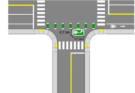

Page Intentionally Left Blank

Intersection markings and signs increase the visibility of people biking and help with navigation. They can help define that path for people biking, reducing conflicts with drivers, and can help them navigate complex intersections. Markings can also help increase the visibility of people biking to drivers helping contribute to a safer environment.
This section includes descriptions and detail drawings for the markings and signage recommended to accommodate biking through intersections. It is intended to be used as a reference to support the "Intersection Elements" and "Intersection Details" sections.
The following standard markings may be used at intersections, driveways, and conflict zones throughout CYMPO.
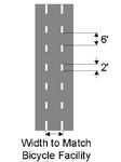
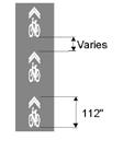
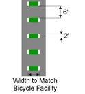
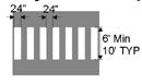
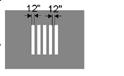
Dashed markings, also called “conflict markings” or “crossbikes”, may be used alone or in combination with green colored pavement to mark extensions of bike lanes through intersections, driveways, and other locations. These markings serve to increase awareness of where people biking may be positioned in the roadway and can help identify the path for people biking and guide them in movements which may be difficult to discern. For more information, see MUTCD Section 9E.03.
Green colored pavement may be used to enhance visibility of locations where people biking are expected to operate. Specifically, it may be used to enhance conflict markings, bike boxes, and other pavement markings. Green pavement shall not be used in place of dotted lines.
High visibility crosswalks, also called “continental” crosswalks, improve pedestrian safety by increasing driver awareness and clearly delineating pedestrian right-of-way. For more information, see MUTCD Section 3B.18.
Marked crosswalks across a bike lane increase the visibility of people walking to people biking and indicate the priority of people walking. At uncontrolled crossings, yield lines can be added at the bike lane approach to further indicate the priority of people walking.
Yield lines, also known as “shark teeth” are typically used in advanced of uncontrolled conflict zones such as crosswalks, crossbikes, driveways, or alleyways to indicate to the yielding vehicle to either yield to people walking and/or biking.


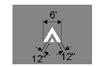
Yield lines consist of a triangle pointing toward approaching vehicles and span across an approaching lane to indicate the point to which the yield is intended or required to be made. For more information, visit MUTCD Section 3B.16.
Yield lines in the bike lane are typically used in advance of a crosswalk or other conflict zones with people walking to indicate that the person biking yield to people walking.
Bike detector markings indicate the optimal placement for a person biking to actuate a signal. Additional signage and markings, including WAIT HERE FOR GREEN text, may be used to supplement the markings per MUTCD Section 9E.15.
Bike symbols can be utilized on their own or in conjunction with directional markings to indicate where a person biking should position themselves in the road. For more information on symbols and markings, see MUTCD Figure 9E-1.
Vertical deflection markings (Section 2C.29 of the MUTCD) are used in advance of speed humps, speed tables, and raised bike and/ or pedestrian crossings and are intended to prompt drivers to slow down in advance of these vertical deflection treatments.
Vertical deflection markings are used in advance of raised pedestrian crossings within the bikeway to alert people biking of the presence of vertical shifts in the roadway and to slow down.
The TURNING VEHICLES YIELD TO BICYCLES AND PEDESTRIANS (MUTCD R10-15 alt) can be used to indicate to drivers turning on a permissive left or right to yield to people walking or biking. If possible, this sign should be mounted on the far side of the intersection to improve visibility to turning vehicles.
Where yield lines are used to indicate to drivers the location at which they should yield to people biking or walking, a YIELD HERE TO BICYCLES (MUTCD R1-5 alt. A) or YIELD HERE TO BICYCLES AND PEDESTRIANS (MUTCD R1-5 alt. B) sign may be used.
The BEGIN RIGHT TURN YIELD TO BIKES sign (MUTCD R44) should be used at intersections where right-turning vehicles must yield to bicyclists proceeding straight through the intersection.
The BICYCLE WARNING SIGN (MUTCD W11-1) should be used to warn drivers in advance of locations where unexpected entries into the roadway by people biking may occur or at designated crossbikes. Similarly, the BICYCLE/PEDESTRIAN WARNING SIGN (MUTCD W11-15) is used to alert drivers of where both people walking or biking may be crossing.
The NO TURN ON RED (MUTCD R10-11) sign should be used at intersections where it is necessary to prohibit right turns to enhance the safety of people walking and biking. NO RIGHT TURN ON RED signs are often required at protected intersections and at intersection legs using bike boxes.
BIKES YIELD TO PEDESTRIANS (MUTCD R9-6) can be used where people biking must yield to people crossing a bikeway or where there is a shared space for people walking and biking and bikes must yield to the movements of people walking.
The TO REQUEST GREEN WAIT ON BICYCLE SYMBOL (MUTCD 10-22) should be used at intersections where in-pavement bike detection is used to trigger a green light or dedicated bike signal. This sign helps alert the person biking where to position their bike in order for their presence to be detected by the traffic signal.

The LEFT TURN MUST USE TURN BOX (MUTCD R11-20) may be used to inform people biking approaching the intersection that they are permitted to use the designated turn to make a left turn at the intersection while the LEFT TURN BOX (MUTCD D11-20A) sign helps to guide people biking to the two-stage left turn box.

At intersections utilizing bike boxes STOP HERE ON RED with EXCEPT BICYCLES (MUTCD R10-6a, R3-7bP) can be used to supplement the stop line.
Page Intentionally Left Blank
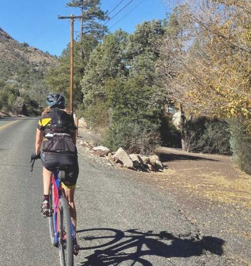

Page Intentionally Left Blank

Bike facilities and parking and loading facilities may both occupy a similar space between the driving lanes and the curb. Both types of facilities also play an important role to vulnerable road users; people who are on bikes, and people who are exiting vehicles - especially those with disabilities who require access to level walkways on the curb. With some planning, the needs of both groups can be met through thoughtful designs, as described on the following pages:
Generally, on-street parking should be designed following local standards. Where a buffered or protected bikeway is placed next to on-street parking, the buffer space shall be at least 3'. Accessible parking spaces shall be provided where other designated on-street parking is provided. Parallel on-street parking spaces may be located at the end of a block with access to existing curb ramps, although they may also be located mid-block where a curb ramp is provided. Sample configurations for accessible on-street parking at block end and mid-block locations are shown below.
Provide an access aisle of at least 5-feet in width for vehicle lift deployment and accessing the designated crossing. The aisle must connect to a pedestrian access route via a curb ramp or blended transition. A1
A2
If a pedestrian aisle is not provided, a signed accessible space must be located at the end of a block face and the adjacent sidewalk must be free of obstructions for vehicle lift deployment. See the End of Black Accessible Space Configuration option for an example of this treatment.
B1
The bikeway may be narrowed to 4 foot at accessible parking spaces in constrained areas.
B2
Detectable warning surfaces should be placed at the transition between the sidewalk and the crossing.
Rear access aisles should be painted for driver side access to the sidewalk.
Bike yield lines and a crosswalk across the bikeway indicates to people biking to yield to people walking.
When the accessible parking space is at the end of the block, Median refuge islands are recommended to prevent parking encroachment on the accessible space and path.
The accessible parking concepts shown are an example of how treatments could be combined to maintain a comfortable place for people walking and biking while also supporting people with disabilities. For formal design guidance, refer to the following documents or others, as new guidance becomes available:
• FHWA MUTCD
• NACTO Urban Bikeway Design Guide
• AASHTO Guide for the Planning, Design, and Operation of Pedestrian Facilities
• AASHTO A Policy on Geometric Design of Highways and Streets
• PROWAG technical requirement R310.2, Table R211 for frequency and availability of ADA parking spaces.
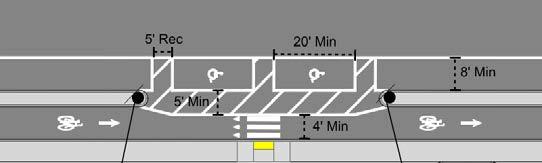


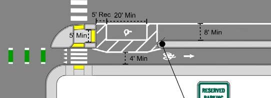
Loading zones may be strategically placed to accommodate passenger and/or commercial loading and unloading in front of businesses, schools, hotels, or other key locations. Where possible, the bikeway should be maintained through the loading zone. Where passenger loading is expected, a curb ramp, crosswalk, and detectable warning surfaces should be present. Yield markings should be placed in the bikeway to indicate to people biking to slow down. Bollards or other vertical elements should be used to ensure people do not park vehicles in the bikeway. Green conflict markings may also be striped in the bikeway through the loading zone to indicate the shared space for all users.
Recommended Features
Provide an access aisle of at least 5-feet in width for the entire length of the loading zone for vehicle lift deployment and accessing the designated crossing. The aisle must connect to a pedestrian access route via a curb ramp or blended transition.
The length of the loading zone should be at least 20 feet but may be longer to accommodate the length and number of vehicles expected to use the space.
Optional Features
The bikeway may be narrowed to 4 foot at loading zones in constrained areas.
Detectable warning surfaces should be placed at the transition between the sidewalk and the crossing.
Bike yield lines and a crosswalk across the bikeway indicates to people biking to yield to people walking.
Curb ramps should wide enough to accommodate the expected dollies/hand trucks or other delivery devices that may be used.
The loading zone concepts shown are an example of how treatments could be combined to maintain a comfortable place for people walking and biking while also supporting people with disabilities. For formal design guidance, refer to the following documents or others, as new guidance becomes available:
• FHWA MUTCD
• NACTO Urban Bikeway Design Guide
• AASHTO Guide for the Planning, Design, and Operation of Pedestrian Facilities
• AASHTO A Policy on Geometric Design of Highways and Streets
• PROWAG technical requirement R310 for accessible passenger loading guidance and PROWAG R302.7 for surface guidance
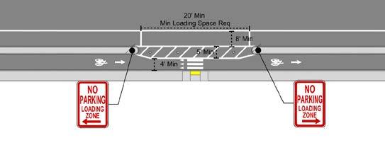
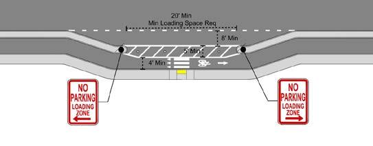

Page Intentionally Left Blank

Transit and bikeways are complimentary modes of transportation, as biking can provide a great option to cover the "last mile" connection between a transit stop and a final destination. However, without consideration, buses and bikes may compete for curb space. This section presents options for the design of bus stops which are compatible with bike facilities:
Where a full bus island cannot be provided due to right of way or other space constraints, it is still desirable to maintain separation between the bike lane and bus stop. In these cases, the bike lane may be raised to sidewalk level and runs along the bus boarding area. When no buses are present, people can bike through the boarding area and people waiting for the bus wait on the sidewalk out of the bikeway. People biking yield during bus loading and unloading. Detectable warning strips may be placed along the edge of the sidewalk where passengers step into the raised boarding area and along the curb where passengers board the bus. The whole width of the separated bicycle lane can be used as the accessible boarding area for wheelchair lifts from the bus. However, stops must provide wheelchair users an accessible waiting area outside of the bike lane.
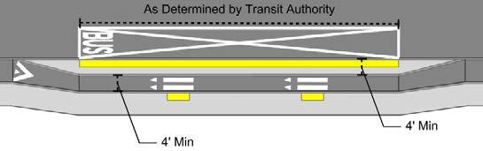
Bus boarding areas must have a 5 x 8 foot clearance space where boarding and alighting occurs for ramp deployment and have a 4 foot clear pedestrian path (ADA Std. 403.5.1).
A2 Raise the bike lane to sidewalk level throughout the length of the intended bus stop.
Bike yield lines and a crosswalk across the bikeway indicate to people biking to yield to people walking.
The bikeway may be narrowed to 4 foot at bus islands in constrained areas.
The accessible waiting area is on the sidewalk. Any transit amenities should be placed on the sidewalk.
Detectable warning surfaces should be placed at the transition between the sidewalk and the crossing.
Detectable warning surfaces should be placed along the entire length of the edge of the boarding platform.
A minimum 4 foot wide buffer should be place between the curb and the bikeway.
The bus island concepts shown are an example of how treatments could be combined to maintain a comfortable place for people walking and biking while also supporting people with disabilities. For formal design guidance, refer to the following documents or others, as new guidance becomes available:
• FHWA MUTCD
• NACTO Urban Bikeway Design Guide, Transit Street Design Guide
• AASHTO Guide for the Planning, Design, and Operation of Pedestrian Facilities
• AASHTO A Policy on Geometric Design of Highways and Streets
• Accessibility requirements ADA Std. 810.2.2
Where bus volumes are low (less than four buses per hour) and/or other constrains prevent the construction of stops which separate the bus from the bike lane, curbside bus stops are a low-cost option. In these stops, the bus merges into the bike lane, and people biking must either merge into traffic to bypass the bus or wait for the bus to move. Where on street parking is present, a curbside pullout may be used and the bike lane can be routed around bus stop. This configuration may be more comfortable than the traditional curbside bus stop. In all cases, green conflict markings should be used to indicate the shared area for all users.
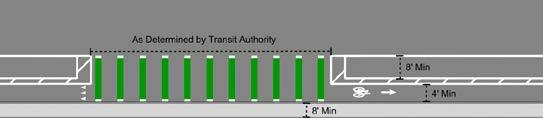
Bus boarding areas must have a 5 x 8 foot clearance space where boarding and alighting occurs for ramp deployment and have a 4 foot clear pedestrian path (ADA Std. 403.5.1).
A2 Paint conflict markings through the entire width of the bus stop to indicate to people biking buses may stop there.
Bike yield lines indicate to people biking they should yield to the bus.
The accessible waiting area is on the sidewalk. Any transit amenities should be placed on the sidewalk.
The bus island concepts shown are an example of how treatments could be combined to maintain a comfortable place for people walking and biking while also supporting people with disabilities. For formal design guidance, refer to the following documents or others, as new guidance becomes available:
• FHWA MUTCD
• NACTO Urban Bikeway Design Guide, Transit Street Design Guide
• AASHTO Guide for the Planning, Design, and Operation of Pedestrian Facilities
• AASHTO A Policy on Geometric Design of Highways and Streets
• Accessibility requirements ADA Std. 810.2.2

Page Intentionally Left Blank

Wayfinding helps people navigating from one location to another, using visual cues and information systems to guide riders. Clear signage and markers help people biking avoid getting lost, minimize travel time, and enhance their overall experience. Good way finding systems can also increase the comfort of people biking by directing riders to lower stress routes or to locations where bike facilities are present. This section presents some options for wayfinding signage, although local agencies may wish to develop a comprehensive, branded wayfinding program.
MUTCD Section 9b.20 Bicycle Guide Signs presents comprehensive guidance on signs and Section 9B.01 of the MUTCD gives specific design details on the placement of signs including mounting height and lateral placement from the roadway. The information in the following section provides information on key signage which can help to guide people biking through CYMPO.
9D-1. Guide Signs and Plaques for Bicycle Facilities (Sheet 2 of 3)
Indicates to people biking that they are riding along a designated bikeway and alerts people driving to be aware to potentially expect higher volumes of bike riders along the roadway. Confirmation can be as simple as a BIKE ROUTE (MUTCD D11-1) or can be a community branded sign with additional details such as distances to major destinations along the route.
Confirmation Signs should be placed every 2-3 blocks along a bike boulevard, but especially after turns to confirm to riders they are taking the correct route. For shared use paths, confirmation signs should be placed every quarter to half mile.
Indicates to people biking that the intended bike path turns from one street to another. Arrows are used with these signs to indicate the direction people biking should follow in order to remain on the bikeway.
9D-1. Guide Signs and Plaques for
Figure 9D-1. Guide Signs and Plaques for Bicycle Facilities (Sheet 1 of 3)
Turn signs should be placed on the near-side of intersections where the bike route turns.
16 Where the arrow is at the extreme right,
17 Unless a sloping arrow will convey a clearer should be either horizontal or vertical.
18 If several individual name signs are assembled same horizontal width.
19 Travel times should not be used on Bicycle Support:
20 Travel times can vary greatly for bicyclists type, and type of facility.
16 Where the arrow is at the extreme right, the bicycle symbol should be to the left of the destination legend.
Section 9D.02 Bike Route Guide Signs (D11-1 and D11-1c)
Section 9D.02 Bike Route Guide Signs (D11-1 and D11-1c)
17 Unless a sloping arrow will convey a clearer indication of the direction to be followed, the directional arrows should be either horizontal or vertical.
Support:
Support:
Decision signs indicate to people biking that the there are two or more bikeways that converge/ diverge and inform the rider of which route leads where. These signs often include information such as directional arrows and distances to key destinations.
Section 9D.02 Bike Route Guide Signs (D11-1 and D11-1c)
Support:
18 If several individual name signs are assembled into a group, all of the signs in the assembly should have the same horizontal width.
01 The Bike Route Guide (D11-1 or D11-1c) sign (see Figure 9D-1) is used where no unique designation of routes is desired. Sections 9D.04 through 9D.07 contain information for Bicycle Route signs where the bicycle route is designated by number, name, or both.
01 The Bike Route Guide (D11-1 or D11-1c) sign (see Figure 9D-1) is used where no unique designation of routes is desired. Sections 9D.04 through 9D.07 contain information for Bicycle Route signs where the bicycle route is designated by number, name, or both.
19 Travel times should not be used on Bicycle Destination signs. Support:
Option:
Option:
01 The Bike Route Guide (D11-1 or D11-1c) sign (see Figure 9D-1) is used where is desired. Sections 9D.04 through 9D.07 contain information for Bicycle Route designated by number, name, or both.
Option:
20 Travel times can vary greatly for bicyclists based on a variety of factors including individual speed, bicycle type, and type of facility.
02 Bike Route Guide signs may be provided along designated unnumbered, unnamed bicycle routes to inform bicyclists of bicycle route direction changes and to confirm route direction and destination.
02 Bike Route Guide signs may be provided along designated unnumbered, unnamed bicycle routes to inform bicyclists of bicycle route direction changes and to confirm route direction and destination.
02 Bike Route Guide signs may be provided along designated unnumbered, unnamed bicyclists of bicycle route direction changes and to confirm route direction and destination.
03 If used, Bike Route Guide signs may be repeated at regular intervals so that bicycles entering from side streets will have an opportunity to know that they are on a bicycle route. Similar guide signing may be used for shared roadways with intermediate signs placed for bicycle guidance.
Decision signs should be placed on the near-side of intersections where two or more bikeways meet.
03 If used, Bike Route Guide signs may be repeated at regular intervals so that bicycles entering from side streets will have an opportunity to know that they are on a bicycle route. Similar guide signing may be used for shared roadways with intermediate signs placed for bicycle guidance.
03 If used, Bike Route Guide signs may be repeated at regular intervals so that will have an opportunity to know that they are on a bicycle route. Similar guide roadways with intermediate signs placed for bicycle guidance.
04 The Alternative Bike Route Guide (D11-1c) sign may be used to display a word legend that provides information on route direction, destination, and/or route name in place of the “BIKE ROUTE” word legend on the D11-1 sign (see Figure 9D-1).
04 The Alternative Bike Route Guide (D11-1c) sign may be used to display a word legend that provides information on route direction, destination, and/or route name in place of the “BIKE ROUTE” word legend on the D11-1 sign (see Figure 9D-1).
04 The Alternative Bike Route Guide (D11-1c) sign may be used to display a word information on route direction, destination, and/or route name in place of the “BIKE D11-1 sign (see Figure 9D-1).
Page Intentionally Left Blank

Page Intentionally Left Blank

Safe, convenient, and accessible bike parking is an important component of the bike network. People may make the choice regarding whether or not to bike based on if there is parking at their destination where they feel confident their bike will not be damaged or stolen. In order to ensure this, bike parking should be reliable available throughout the region, especially where there are concentrations of businesses or other destinations. The following section provides guidance on where to install bike parking and the potential options which could be provided.
Additional bike parking guidance is provided in Association of Pedestrian and Bicycle Professionals (ABPB) publications, including the Essentials of Bike Parking (2015) and the Bicycle Parking Guidelines, 2nd Edition (2010). APBP provides state of the practice information including sample long- and shortterm parking supply rates for various land uses, site planning, bike rack selection, and placement/spacing.
Bike parking is essential to encourage biking as a mode of transportation. Proper bike parking facilities not only promote biking but also address concerns such as security, convenience, and efficient use of space. As the region implements the Active Transportation Plan, the following additional considerations and guidance should be considered.
Bike parking should be located at all destinations where people may choose to bike, including:
• Commercial Districts, Grocery Stores, and Convenience Stores
• Parks and Recreation Sites
• Schools and Universities
• Libraries, Community Centers, Churches, Post Offices Museums, and Other Community Serving Destinations
• Employment Centers
• Transit Centers
• High Density Residential Areas
Bike parking may be located within the public right-of-way on sidewalks or within on-street parking spaces. It may also be located on private property if built by developers, especially in secured garages or bike cages.
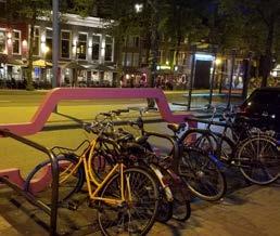
The type of bike parking selected should be based on factors such as the anticipated duration of a stay, type of destination, security needs, and proximity to a destination. Based on this, the designer can determine whether long or short term bike parking is preferable.
Short term bike parking accommodates people who are visiting a destination for approximately two hours or less, such as a grocery store, healthcare office, restaurant, or gym. Short term visitors may be less familiar with the area and prioritize visibility and access to their bike, and so short term bike parking spaces should be placed within eyesight of a building entrance. Short term bike parking in other locations, such as alleys or unsecured locations in parking garages, may be less secure and should be avoided. The following considerations are relevant for short-term bike parking:
• Placed in visible locations close to entrances (50 feet or less)
• Racks should be securely fastened to the ground, accommodate U-locks, and support the bicycle at two points to allow the frame and both wheels to be locked
• Consider adding a weather-protected cover
• Should be well lit
• Location should be visible to the public or seen from within the destination
• May be co-located with amenities such as bike repair stations
• May be designed with creative shapes or colors
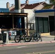
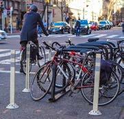
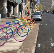
Long term bike parking is intended to store bike for several hours or more. This type of parking accommodates regular visitors, like employees, students, residents, or public transit users. Because users leave their bike for long periods unattended, security is critical, as is weather protection. That said, location convenience is less important for long term users. People may choose to leave their bike long term in a secure space in a building lobby or parking garage, as opposed to prioritizing highly visible locations in front of main entrances. The following considerations are relevant for long term bike parking:
• Signage should be present for first time users
• Locations may vary, secure facilities are most important
• Should be directly accessible without stairs
• Should be designed to fit larger bikes like cargo bikes
• May include outlets for e-bike charging
• May be co-located with other amenities like a bike shop or repair station
• Security may include individual user locks, keys, smart cards, mobile applications, or other technologies
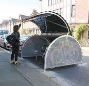
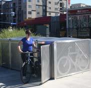
Electric bicycles or “e-bikes” are bicycles with electric motors that provide assistance in generating momentum through pedaling or via a hand throttle. With the rising popularity of e-bikes, government agencies, land use developers, and other providers are beginning to incorporate this new mode into their transportation facilities.
To accommodate the unique needs of e-bikes, specialized parking solutions are essential. These measures address factors such as size, functionality, charging needs, and security to support the growing popularity of e-bikes.
• E-bikes' wider tires and heavier frames necessitate larger racks or increased spacing between bikes.
• Facilities may include charging stations near accessible power sources, with additional room for ease of use.
Enhanced Security:
• Secure racks with locks for both the frame and front wheel, or access-controlled systems (e.g., key cards, mobile apps), can help prevent theft.
• Bike lockers offer both security and space for larger e-bikes and cargo bikes, with charging options included.
• Accessible parking with integrated charging infrastructure encourages e-bike use by residents and employees, reducing local vehicle trips.
• Weather-protected parking prevents damage to sensitive electronic components
• E-Bike parking initiatives complement bikeshare and scootershare systems, increasing the range and convenience of on-demand options.

Page Intentionally Left Blank

Page Intentionally Left Blank

Bicyclist movements can often be controlled by vehicle or pedestrian signals. However, where protected bike lanes are used, at complex crossings, where there is a desire to let people biking get a head start, or other unique situations, a bike signal may be used. Bike signals are signals specifically designed to facilitate crossings for people on bikes. They operate similarly to vehicle signals, but may include special bike symbol in the signal head. The should only be used in conjunction with a conventional traffic signal, and can help address safety or operational challenges. This section provides high level guidance on when and how to use bike signals, however, the decision of if and when to install a bicycle signal and how to design phasing should be made based on engineering judgment and consider the needs of everyone crossing through the intersection.
MUTCD Chapter 4H Bicycle Signals presents comprehensive guidance on the installation and other elements of bicycle signals. The information in the following section provides guidance on when bicycle signals may be appropriate.
Bike signals may be appropriate in many scenarios, and the determination to use them should be based on an holistic evaluation of the study area, warrant considerations, and engineering judgement. The Federal MUTCD provides warrants for the installation of bike signals where a new traffic control signal is being installed in Chapter 4C, however, it is noted that the installation of bike signals at existing traffic control signals should be made based on engineering judgement.
Locations where it may be appropriate to install bike signals include, but are not limited to:
• Providing a protected bicycle signal phase
• Providing a leading or lagging bicycle interval or to make it legal for a person biking to enter the intersection during an all-pedestrian phase
• Controlling a bicycle through movement for a bicycle lane running on the right-hand side of a rightturn lane, such as for protected bike lanes or through bike lanes
• At protected intersections, dedicated intersections, or bend outs
• At intersections with unique bicycle movements, such as a diagonal transition or to provide for a bike through movement across a T intersection where no concurrent vehicle movement exists
• Where there are high volumes of right turning vehicles (greater than 150 vehicles per hour for a oneway separated bikeway or 100 vehicles per hour for a two-way separated bikeway or sidepath)
• Controlling a bicycle through movement for contraflow bike lanes or two-way bikeways
• Locations where existing traffic signal heads are not visible to people biking
In general, bike signals should be consistently installed along a corridor if they are used. Otherwise, it can be confusing for people biking if they must look for a combination of vehicle, pedestrian, and/or bike signals.
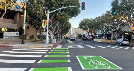
The MUTCD establishes requirements for where bike signal displaces can be placed at an intersection. Generally, they may be placed near- and far-side at an intersection and are co-located with vehicle traffic signals. The following guidance supplements what is noted in the MUTCD.
Bicycle signal faces my be designed as standard signal faces or may include a bike stencil. The following elements should be considered in bike signal design:
• If designed as a standard signal face, a “BICYCLE SIGNAL” plaque (R10-10b) is required. The sign is optional if a bike stencil is used.
• Bike signal faces may be designed using an 8 inch or 12 circular indicators. If a secondary, nearside signal is installed, 4 inch circular indicators may be utilized on the nearside signal.
• One bike signal face is sufficient, although a second face may be provided to provide additional clarification and guidance for people biking.
• Bike signal heads to should be designed to be visible by people biking. This is especially important in locations with contraflow or two-way bikeways.
• Bike signals may be designed with shielded louvres to prevent confusion for vehicle drivers.
• Bike signals shall be placed a minimum of 7 feet above sidewalk or the ground. If a 4-inch nearside signal is used, the signal face shall be a minimum of 4 feet and a maximum of 8 feet above the ground.
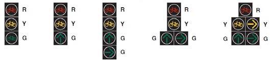
Source: FHWA MUTCD Attachment IA-16-1
The bike signal phase may or may not occur every phase. If actuation is required, passive actuation is preferred using bike loop detectors over requiring people biking to use push buttons. If push buttons are used, they should be mounted in a way that does not require people biking to dismount. If a push button is used, it shall be accompanied by appropriate regulatory signs (MUTCD R10-4, R10-24, or R 10-26) explaining the purpose and operation of the push button. If the push button is intended to be used by both people walking and biking, the button must be designed to meet all accessibility needs.
There are a variety of types of phasing which may be used to reduce potential conflicts between people biking and other roadway users, or to increase convenience for people biking. Overall waiting time, among other elements, should be considered when determining a signal phasing plan. The following section presents a non-exhaustive discussion of potential phasing options. For more information, please see the NACTO Urban Bikeway Design Guide and/or the FHWA Separated Bikeway Planning and Design Guide.
There are no national standards for determining the appropriate clearance intervals for bike signals. People biking typically require longer minimum green times that drivers because people biking move slower than drivers, and therefore bicycle minimum clearance times should be determined using the time it would take an average person to cross the width of the intersection on a bike. The NACTO Urban Bikeway Design Guide recommends utilizing 14 feet per second, or 9.5 miles per hour, as an average intersection crossing speed. Additional time may be provided for start up time. Yellow and all-red intervals may be incorporated into the vehicle phases as long as the minimum clearance time is met.
The following phasing options may be considered at bike signals:
Leading Bike Interval
Protected
People biking are provided a 3to 5- second head start in front of all vehicles. This treatment may also provide a head start for people walking.
Vehicular right turns on red are prohibited during the bike through movement. Then, through bike movements are halted drivers are permitted to turn across the bike path.
• People walking and biking enter the intersection before drivers
• Improved visibility and reduced conflict potential between all users
• People biking and walking are fully separated from right-turning vehicles
• Drivers are not required to yield when turning
• Increased delay for drivers
• May be less appropriate in areas with high volumes of right-turning drivers
• Longer cycle lengths may be required
• Requires a right turn lane
ProtectedPermissive
Bike Only Phase
Through moving vehicles start at the same time as people biking and walking. A flashing yellow turn phase is then provided for right turning vehicles.
All vehicle traffic is stopped and people biking may move through the intersection. The current MUTCD does not allow bike scrambles.
• People walking and biking can enter the intersection before right-turning vehicles
• Improved visibility and reduced conflict potential between all users
• People biking and walking are fully separated from drivers
• Drivers are not required to yield to other users
• May be less appropriate in areas with high volumes of right-turning drivers
• Increases delay for all users which may result in reduced compliance
Page Intentionally Left Blank

Page Intentionally Left Blank

Edge line rumble strips are a safety measure for reducing roadway departure crashes by creating noise and vibrations that alert drivers when they drift outside the travel lane. These strips are often used on road shoulders, where they help keep drivers within lanes. This section presents some guidance for edge line rumble strips.
Edge line rumble strips are grooved patterns placed along the outer edges of roadways to improve safety. When a vehicle drifts over them, the resulting vibration and noise alert drivers that they're veering off the road, reducing the risk of run-off-road crashes. These strips are particularly effective on rural roads and highways where fatigue or distractions can lead to crashes, providing an added layer of protection, especially at night or during adverse weather conditions. Rumble stripes are rumble strips painted with a retroreflective coating, enhancing pavement edge visibility during nighttime and severe weather conditions.
The figure below provides a graphical representation of rumble strip dimensions according to the FHWA:
• Offset (A): Distance from the pavement marking (delineating the edge of the traveled way) to the inside edge of the rumble strip.
• Length (B): Dimension of the strip that is perpendicular to the travel directions of the roadway. This is often referred to as the "transverse width" of the rumble strip.
• Width (C): Dimension of the strip that is parallel to the travel direction of the roadway.
• Depth (D): The maximum distance from the surface of the roadway to the bottom of the rumble strip.
• Spacing (E): The distance between adjacent rumble strips. It is most often measured from the center of the strip to the center of the adjacent strip.
• Gap (F): The distance from the edge of the rumble strip to the edge of the rumble strip when there is a break in the pattern. Gaps are commonly used to allow bicycles to cross the rumble strip pattern and to allow turning movements at intersections and driveways.
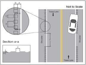
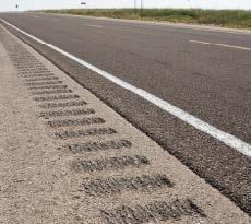
When rumble strips are implemented on bicycle routes or roadways with striped shoulders, adjustments are needed to make them more tolerable for cyclists. This includes optimizing the strips’ dimensions and placement, such as 12-inch center-to-center spacing, lengths of 6–8 inches, widths of 6 inches, and a depth of 3/8 inch. Placing these strips along the roadway edge line helps minimize encroachment on the shoulder space that used by bicyclists. Additionally, incorporating a bicycle-friendly gap pattern—providing a clear, 12-foot gap every 40–60 feet—enables bicyclists to enter and exit the shoulder more easily, accommodating safe and comfortable shared use of the roadway.
Page Intentionally Left Blank
Page Intentionally Left Blank
Overpasses and underpasses are crucial links in transportation networks, but due to high costs and existing design constraints, upgrading them to support multimodal use is often challenging. It can take years to replace older structures with designs that fully accommodate walking and biking. However, rehabilitating existing overpasses and underpasses presents valuable opportunities to reconfigure these spaces, enhancing safety and accessibility for all users. Strategies for accommodating people biking and walking will differ depending on whether the structure is being reconfigured, retrofitted, or fully replaced. This section presents some guidance for modifying overpasses and underpasses.
Reconfiguring and reconstructing overpasses and underpasses can significantly improve safety and accessibility for people biking. When rehabilitating these structures, there are two primary scenarios to consider: those with sufficient space for adjustments and those that are too narrow to accommodate dedicated bike facilities without structural modifications.
For both overpasses and underpasses with travel lanes over 11' wide or minimal existing shoulder space, reconfiguration may be feasible. Potential modifications include:
• Wider Shoulders or Bike Lanes: Converting narrow sidewalks or adding extra width to shoulders creates safer, more functional spaces for people biking. Ideally, shoulders should be a minimum of 5', with additional width wherever possible to enhance comfort.
• On-Deck Side Paths for Overpasses or Parallel Paths for Underpasses: If people biking are directed to one side of the roadway, reducing lane widths can sometimes allow for a shared-use path that prioritizes biking safety. A physical barrier between the side path and vehicle lanes is recommended for added protection.
For narrower overpasses or underpasses, often less than 26' wide, space may be insufficient for dedicated bike lanes. In such cases, alternative safety measures can be implemented:
• Clear Signage, Road Markings, and Active Warning Beacons can alert drivers to the presence of people biking, enhancing their visibility.
• Reduced or Advisory Speed Limits can help improve safety, especially in areas with heavy bike traffic.
• Advisory Shoulders may be used to create space for people biking without reducing overall lane width.
For newly constructed or reconstructed overpasses and underpasses, there is an ideal opportunity to integrate high-quality bike facilities. Recommended features include:
• Wide Shoulders (at least 8') to comfortably accommodate people biking, or separated bike lanes in areas with high biking demand.
• Continuous Separated Paths for corridors with existing sidepaths, ensuring safe and seamless passage for people biking, regardless of their experience level.
Page Intentionally Left Blank

Page Intentionally Left Blank

Bicycle facility design can impact wildlife movement, leading to potential conflicts in areas where human and animal activities overlap. To reduce crashes and environmental effects strategies include wildlife crossings, fencing, and warning signs, as well as managing vegetation and drainage. Careful planning and maintenance can help protect both people biking and wildlife while preserving natural habitats.
The siting and design of bicycle facilities can affect the movement of wildlife and have other effects on the local natural environment. In areas where human and wildlife activity overlap, wildlife crossings can result in higher rates of vehicle-animal and bicycle-animal crashes. The construction, design, and maintenance of bicycle facilities (and roadways in general) can include considerations to reduce the likelihood of conflicts with wildlife and negative effects on their environment. Resources on this topic include FHWA’s Keeping it Simple: Easy Ways to Help Wildlife Along Roads (2003), FHWA’s Making America’s Highways Safer for Drivers and Wildlife: Wildlife-Vehicle Collision Reduction Study (2008), and Nevada DOT’s The Strategic Integration of Wildlife Mitigation into Transportation Procedures: A Manual for Agencies and Partners (2022).
• Provide wildlife crossing warning signs on roadways that experience high instances of wildlife crossings. This can include seasonal signs that are only present at certain times of year when crossings are most frequent, such as during a seasonal migration.
• Provide wildlife fencing at key locations to reduce conflicts with humans without imposing a burden on wildlife movements. Pair with safe crossing opportunities such as wildlife underpasses or overpasses.
• Consider removing vegetation adjacent to roads, while minimizing the clearance of vegetation in wildlife transition zones near roads where birds and other animals may nest.
• Include sufficient facilities such as drainage, berms, or trenches to prevent runoff into waterways.
• Design and regularly maintain drainage to avoid creating pooled water that may attract wildlife.
• When possible, select routing that avoids key habitats and the most sensitive areas.
• Avoid steep slopes that reduce human awareness of wildlife; if slopes are unavoidable, a landing area may increase visibility.

Page Intentionally Left Blank